9. Embedded Programming
For the individual task this week we emulate a candle.
How good do you need your Random number to be?
Not all applications of randomness require a cryptographically secure sequence of numbers. For a future application we imagine that we could do with a quick bit of code to provide an impression of randomness.
Let’s do a quick experiment to see what we might save in overhead if we rolled our own.
Read a Datasheet
We’ll run our quick and dirty experiment on an Arduino. For our experiment we want the code for randomness to dominate the timing. So we’ll double check the datasheet for the Atmega328p on the correct registers to write to, when toggling a pin.
We’re interested in Arduino pin 13, which sits on Port B, pin 5.
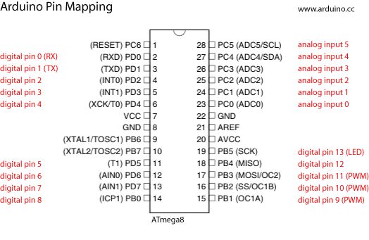
As well as writing to PORTx to set a pin output, we can write to register PINx to toggle pins.

The three main registers directing the output of the Port.

Simple code
Well draw a number and toggle the output. The mark space of the resulting waveform will give us an idea of how the relative methods compare.
The algorithm used here is an XOR-SHIFT Pseudo Random Number Generator. A class of algorithms that use feedback and shifting in a working register to cycle through a number sequence. The quality of the sequence an depend on a number of factors including seed.
int value;

void setup() {
    pinMode(13, OUTPUT);
}

void loop() {
   value = random(255);
   PINB = B00100000;
   value = rnd255();
   PINB = B00100000;
}

// https://www.avrfreaks.net/forum/tiny-fast-prng
uint8_t rnd255(void) {
   static uint8_t s = 0xaa, a = 0;
   s ^= s << 3;
   s ^= s >> 5;
   s ^= a++ >> 2;
   return s;
}
Result
Arduino random(255): 50.1uS DIY rnd255(): 1.5uS
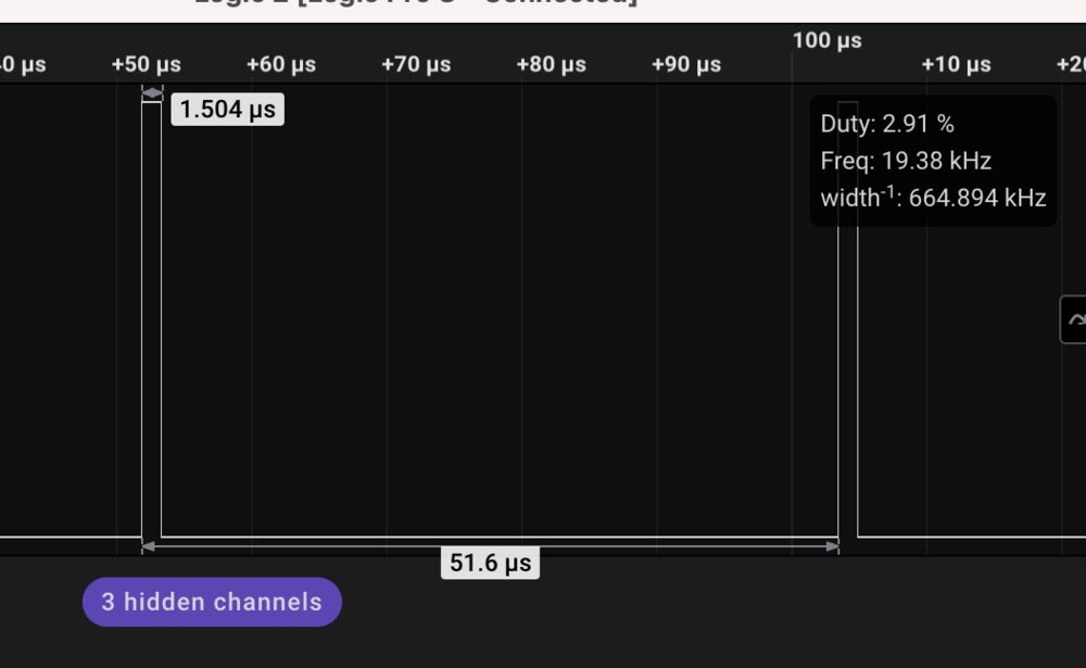
We can see here that the Arduino overheads are significant for a simple application.
Application
In an application we’ve written a candle flicker emulator. Notice that we’ve modified the random generator to output a 7bit number. We want the LEDs brightness to vary over the upper range not the full depth.
I’ve written a couple of arduino sketches with slight variations in the random sequence targetting the peripheral boards that were manufactured for Networking week
The candle flicker algorithm was described by Carlos Pineiro in a youtube video, it’s been modified to make best use of our tiny RNG.
const int ledPin = 3;

unsigned long now = 0;
unsigned long timerA = 0;

void setup() {
  pinMode(ledPin, OUTPUT);
  now = millis();
  timerA = now + 128;
}

void loop() {
  // put your main code here, to run repeatedly:
  now = millis();
  if ( now > timerA ) {
    analogWrite(ledPin, rnd128() + 90);
    timerA = now + rnd128();
  }
}

uint8_t rnd128(void) {
  static uint8_t s = 0xaa, a = 0;
  s ^= s << 3;
  s ^= s >> 5;
  s ^= a++ >> 2;
  return s >> 1;
}
const int ledPin = 3;

unsigned long now = 0;
unsigned long timerB = 0;

void setup() {
  pinMode(ledPin, OUTPUT);
  now = millis();
  timerB = now + 100;
}

void loop() {
  // put your main code here, to run repeatedly:
  now = millis();
  if ( now > timerB ) {
    analogWrite(ledPin, rnd128() + 100);
    timerB = now + rnd128() + 30;
  }
}

uint8_t rnd128(void) {
  static uint8_t s = 0xaa, a = 0;
  s ^= s << 3;
  s ^= s >> 5;
  s ^= a++ >> 2;
  return s >> 1;
}
Programming
To program our boards we need to set up the Arduino environment with the support for the target microcontroller.
Do do this we install the megatinycore board support package.
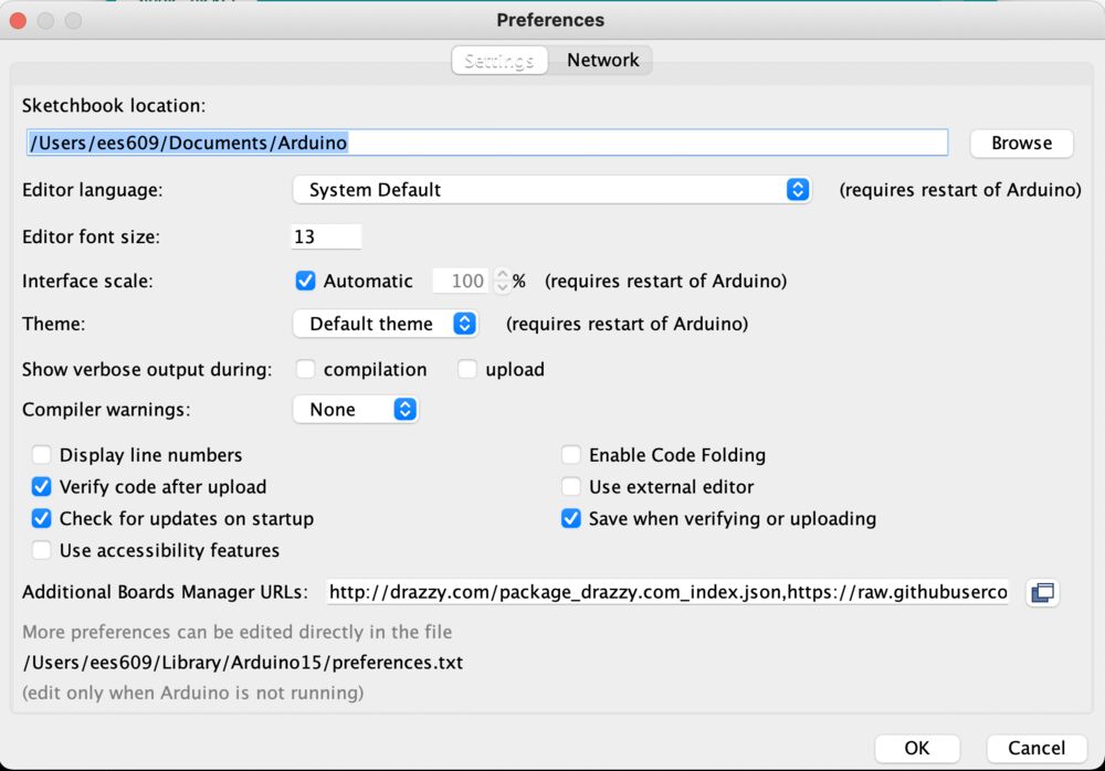
Step 1. Add the following URL to your preferences:
http://drazzy.com/package_drazzy.com_index.json
Step 2. Add install the support for the chips with the Boards Manager…

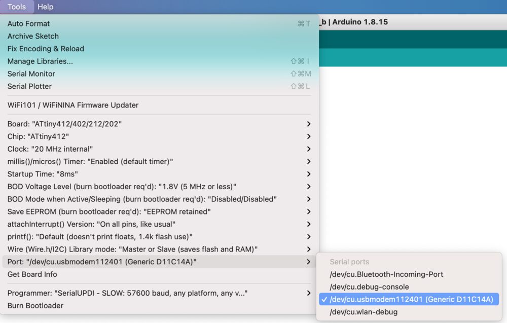
Step 3. Select the correct board/chip for compiling, and the correct Port for upload:

Step 4. Attach programmer to board and hit upload, you should see the good messages

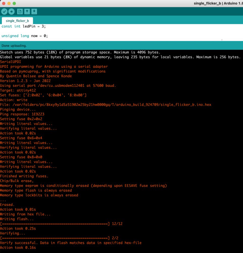
Step 5. Enjoy the show
Group work
Antero and Max implemented a ring oscillator on a number of hardware platforms.
As a minor addition I’ve done a similar thing here, putting the following sketch onto an ATTINY412
void setup() {
  pinMode(0, INPUT);
  pinMode(1, OUTPUT);
}

void loop() {
  while(1){
    digitalWrite(1, !digitalRead(0));
  }
}
The result 427.35kHz square wave.

Reflection
The intent is to see how fast the system will run without any throttling. As can just about be seen from the oscillator images the different systems run at very different speeds as expected.