15. Interface and Application Programming
This week it’s simple interfaces. For my individual effort I made a couple of simple Processing sketches that respond to a serial input from the board that I designed and implemented for Output and Input weeks.
Output Devices details the design and construction of the board for control of a fan. Input Devices details it’s further use describing the input from a sliding potentiometer.
Below we detail the addition of a connector to the same board, to pins that we broke out in preparation for serial comms.
For the individual work I’ll be using the input coming in over serial to change the background colour in one example and to change a property of a particle system in a second example.
For the group work, I got the python example working, relayed to us by our tutor, then took a look at P5.
Hardware
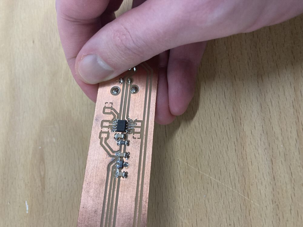
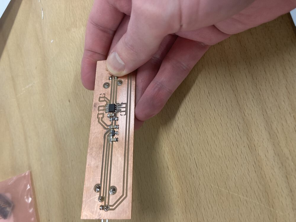
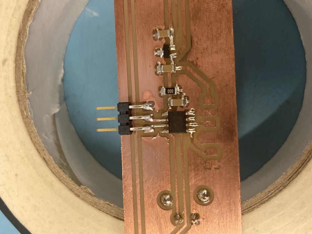
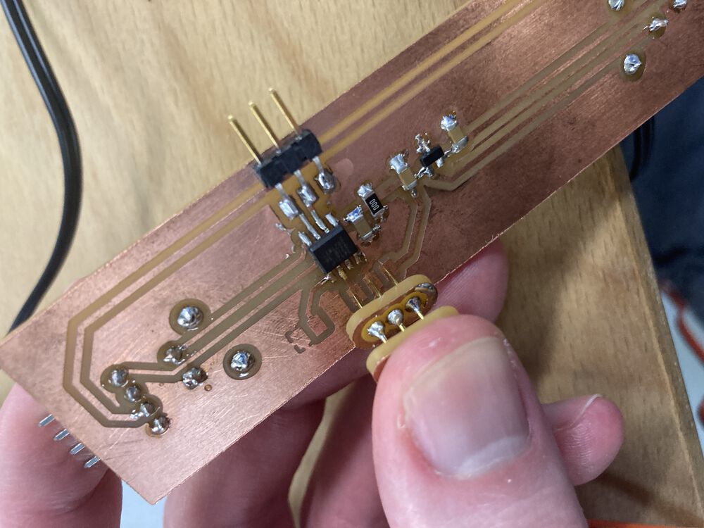
I needed to add a connector to the board for serial comms. For the design and manufacture of the board see Output and Input weeks.
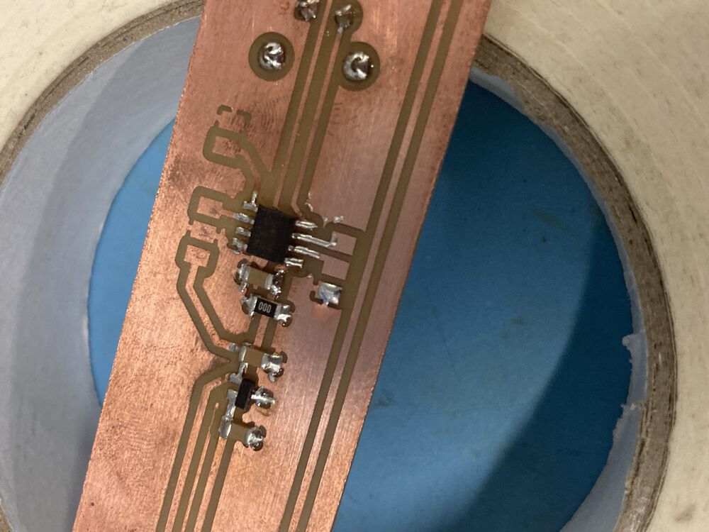
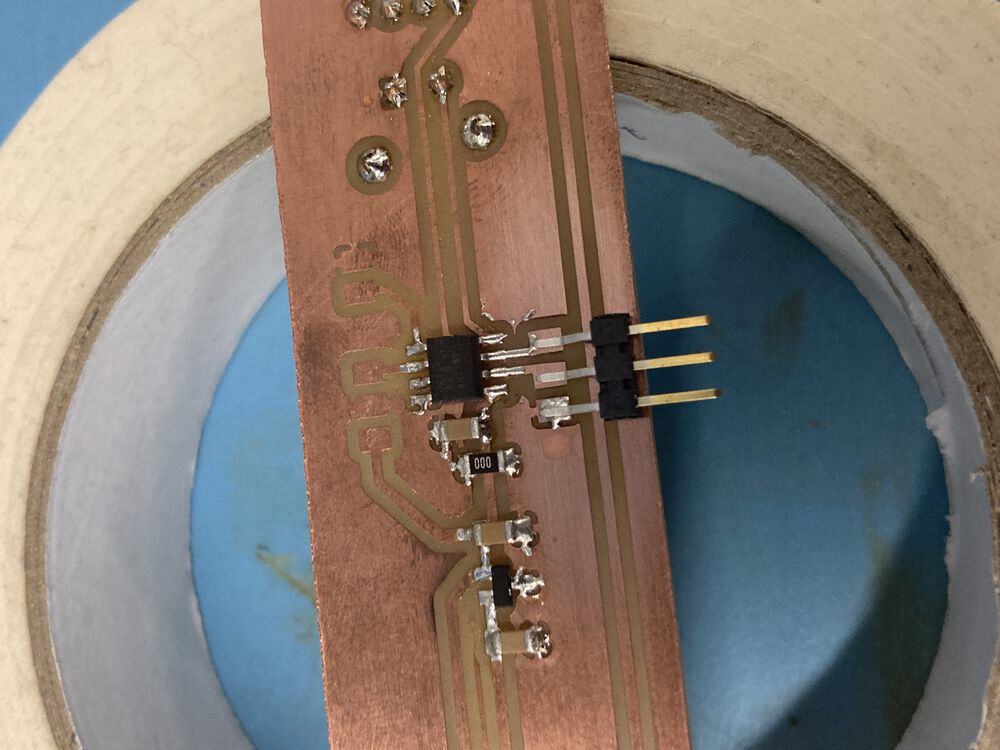
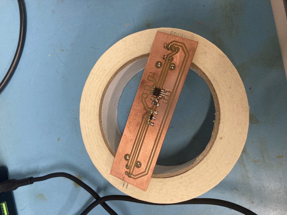
In the following sequence of images we see that the bare copper tarnishes very quickly. This oxide layer would make soldering tricky. It’s quickly fixed with a bit of Scotch Brite. The sequence for putting down a multi pin device: Tin one pad, tack the device down, solder the pins. A roll of tape has many uses. With the slider of the Potentiometer sticking out the back the roll of tape made a perfect prop.
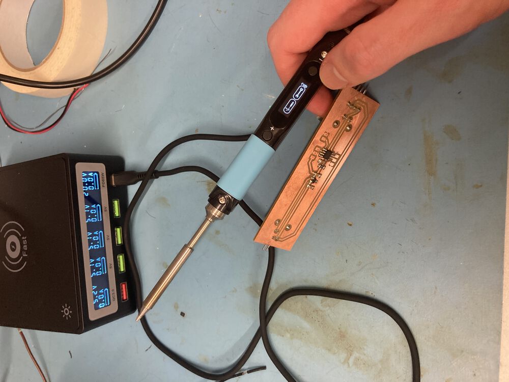
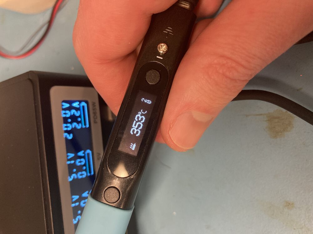
To do this job I tested the Pinecil soldering iron. Had a tendency to hit the buttons as I worked but it performed well in this simple application. I’ll happily use it again.
Programming and bring up
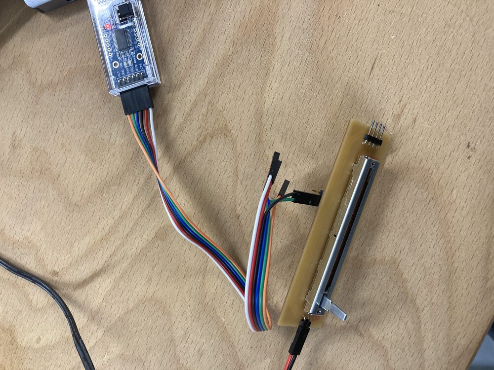
Programming was done using my new pogo pin adapter, whilst the serial connection was done with an off the shelf FTDI cable.
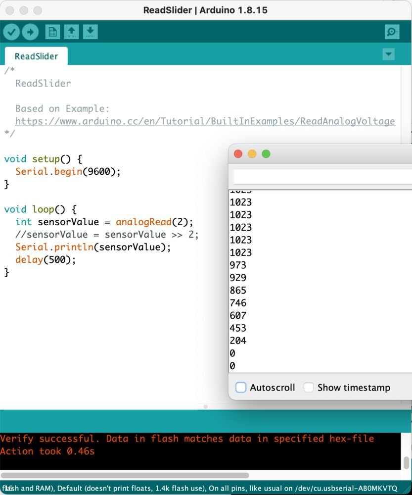
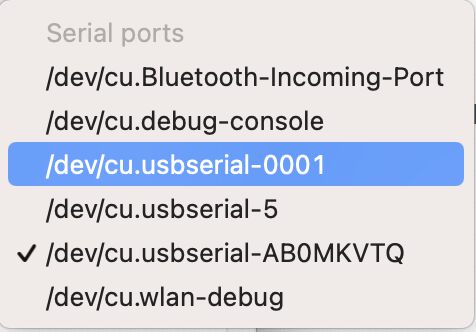
Just to sanity check I put on a simple sketch that I new would interact with the Serial Monitor. Note that we have to program over one port, and under the Tools menu shift to the other USB serial connection for communication purposes. For a Windows user the names of the serial ports may look quite different to ‘COM3’ etc. this work was completed on a MAC.
Hardware issue
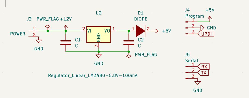
In my original circuit I broke out the post regulator 5V line, to the programming port along with GND and UPDI. Anticipating that I could flash code without powering the board from it’s usual supply. Doing this however seems to make the regulator very hot. I’ve managed not to let out the blue smoke. So I’ve stopped using that method and power up the board and use just UPDI and GND of the programmer. In a future revision if I want to use it in the intended way I could add a diode as illustrated:
Serial communication
We’ll be making use of the slide potentiometer on our Fan Controller board, programmed using the Arduino IDE. We’ve removed the fan temporarily and connected the FTDI cable to the newly soldered connector. Also coming in is the 12V line for power.
The board is set up to transmit a value representing the position of the slider over the serial connection to the receiving software on the PC.
Sending Data
As we’re dealing with multi-byte data its important that we send it down the cable in a reliable and repeatable manner. Based on Neil’s original code, Ivan provided an excellent tutorial showing how we can get the Arduino to construct a simple ‘Frame’. With a leading ‘1234’ followed by our data. With our Slide Potentiometer wired in we wrote the following sketch to send a robust frame with our 10 bit measured output, representing the position of the pot:
/*
  ReadSlider

  Based on the tutorial by Ivan Milara
  https://github.com/ivanmilara/helloworlds_guis/blob/master/sensor_data_generator/sensor_data_generator.ino
*/

void setup() {
  Serial.begin(9600);
}

void loop() {
  int value = analogRead(2);

  //Write the frame
  Serial.write(1);
  Serial.write(2);
  Serial.write(3);
  Serial.write(4);
  Serial.write(lowByte(value));
  Serial.write(highByte(value));

  delay(100);
}
Download RealSlider.ino
Reading Data
To make an interface that makes use of our measured data we use Processing. From the front page of the Processing website:
Processing is a flexible software sketchbook and a language for learning how to code within the context of the visual arts. Since 2001, Processing has promoted software literacy within the visual arts and visual literacy within technology. There are tens of thousands of students, artists, designers, researchers, and hobbyists who use Processing for learning and prototyping.
Simple background change
I took the example provided in our tutorial and tweaked it so that the background colour also changed when the input sent to us from the external slider hardware changed.
Scaling data
The ADC on the micro has 10 bit accuracy ie: you can get a value out of it between 0 and 1023 at full range. The number is transmitted as a 16bit number stored in two bytes.
At the other end we need only an 8 bit number. We take in the two bytes to reform a 16 bit number. This is an oversized container for our original 10 bits. 10 bits is a lot more accuracy than we strictly need, we can discard the two Least Significant Bits. This is a simple operation in code using a ‘shift’ operation, or can be thought of as divide by 4. 1024 / 4 = 256, so even if the number transmitted was as large as it could be: 1023, it will still finish up being small enough to fit into 255 for our call to Background detailed below. You can see in the videos that the behaviour using these numbers is as expected, the background changes through the full range of shades from white to black.
The Sketch:
import processing.serial.*;

//For serial communication
Serial myPort;
int byte1, byte2, byte3, byte4, high, low;
int value = 0;

void setup() {
  /*** Set this so it picks up your board ***/
  myPort = new Serial(this, Serial.list()[3], 9600);
  /*****/

  //size(640, 360);
  fullScreen();
}

void draw() {
  background(value); // Set background from input data

  // Receive the data
  while ( myPort.available() > 0) {  // If data is available,
    byte1 = byte2;
    byte2 = byte3;
    byte3 = byte4;
    byte4 = low;
    low = high;
    high = myPort.read();

    if ((byte1 == 1) & (byte2 == 2) & (byte3 == 3) & (byte4 ==4)) {
      //Reset the preamble.
      byte1=byte2=byte3=byte4=0;
      value = ((256*high)+low);
      println("Counter is "+ value);
      value = value >> 2;
    }
  }
}
Download DataIn.pde
Much like an Arduino sketch has a Setup and a Loop, Processing sketches have a Setup and Draw. The former is run once to configure your environment. The latter is run repeatedly, each time representing in some fashion a frame of visual output. The key line in changing the viewed UI is:
background(value)
where the background colour of the UI is set to be ‘value’, and the rest of the sketch is receiving our serial data from our hardware and storing it as the next ‘value’ or background colour.
Control the lifetime of a Particle
Looking to make a slightly more visual effect I googled for a simple particle system and found this example.
To integrate the live input data a couple of methods were overloaded to accept an input value as the lifetime of a generated particle. So we can see that the slider controls the activity of the particle system. Colours were reversed from the example code so that I wasn’t in the screen reflection. The sketch is made up of three files:
DataInParticle ParticleSystem Particle
The first file is the root of the software and uses the same method to receive the ‘frame’ over serial and extract a ‘value’ representing the position of the slider. But instead of changing the background, we use value to add a particle to the particle system:
  ps.addParticle(float(value));
  ps.run();
The ParticleSystem is the first point where we altered the example code we found, overloading the addParticle method so that it took a parameter we called life:
 void addParticle() {
    particles.add(new Particle(origin));
  }

  void addParticle(float life) {
    particles.add(new Particle(origin, life));
  }
This in turn means we needed an overloaded constructor in the third file to create a particle that had a lifetime fixed at instantiation by parameter not by default:
  Particle(PVector l) {
    acceleration = new PVector(0, 0.05);
    velocity = new PVector(random(-1, 1), random(-2, 0));
    position = l.copy();
    lifespan = 255.0;
  }
  Particle(PVector l, float life) {
    acceleration = new PVector(0, 0.05);
    velocity = new PVector(random(-1, 1), random(-2, 0));
    position = l.copy();
    lifespan = life;
  }
The visual effect end up being a shift between short lived particles that fade away quickly at the top of the screen or particles that live longer making a bigger spray, controlled by our slider:
P5
I also took a look at serial connection in P5 a web version of Processing. P5 is written in Javascript to run in the browser and on the web, but with an API just like the original Processing. But as it’s operating in the sandboxed environment of the browser it won’t natively interact with a serial port, so we need a special library.
The p5.serialport provides a serial connection in the same way that Processing does.
There’s a serial control application that you can download that tests and explores the serial ports on your machine. We can see in the screenshot our data frame coming through:
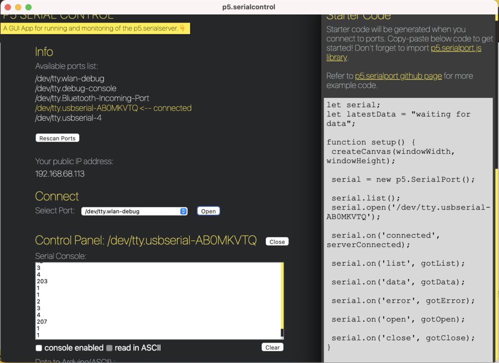
This app also acts as a shim for the serialport library in the javascript environment.
Getting our own code started we can experiment with the p5js online editor First we need to add the library to our html file
<script language="javascript" type="text/javascript" src="https://cdn.jsdelivr.net/npm/p5.serialserver@0.0.28/lib/p5.serialport.js"></script>
Then get going with the sketch where the key lines are:
let serial;
...
serial = new p5.SerialPort();
...
serial.open("/dev/tty.usbserial-AB0MKVTQ");
...
high = serial.read();
Finished code in the editor:
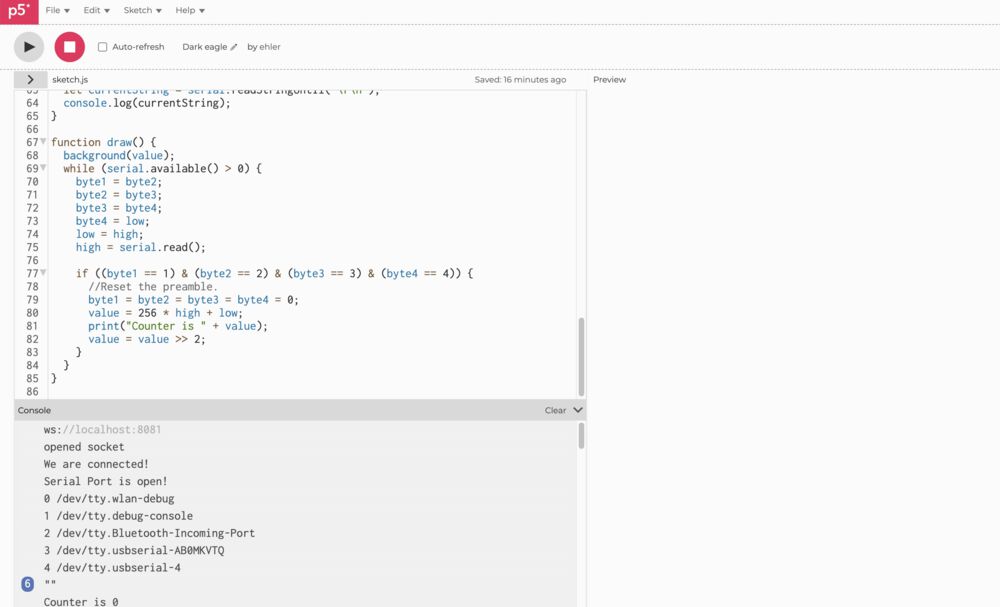
I ported the change background processing sketch, see the whole code:
One difference to using serial in vanilla Processing is that we have a bunch of ‘callbacks’ implemented
// We are connected and ready to go
function serverConnected() {
  print("We are connected!");
}

// Got the list of ports
function gotList(thelist) {
  // theList is an array of their names
  for (let i = 0; i < thelist.length; i++) {
    // Display in the console
    print(i + " " + thelist[i]);
  }
}

// Connected to our serial device
function gotOpen() {
  print("Serial Port is open!");
}

// Ut oh, here is an error, let's log it
function gotError(theerror) {
  print(theerror);
}

// There is data available to work with from the serial port
function gotData() {
  let currentString = serial.readStringUntil("\r\n");
  console.log(currentString);
}
these are responses to browser events caused by the serial connection.
Here’s a video of the working output:
MQTT example
In Networking Week we also produced an example interface using regular processing. This interfaced with a MQTT server to make an LED available to the internet to toggle.
Group Work
All group work are based on the tutorials provided by our instructor Ivan, code downloaded from:
https://github.com/ivanmilara/helloworlds_guis
The main thing that I’ve picked up from this exercise is the idea of packing up my data in a frame for more robust transmission.
Python
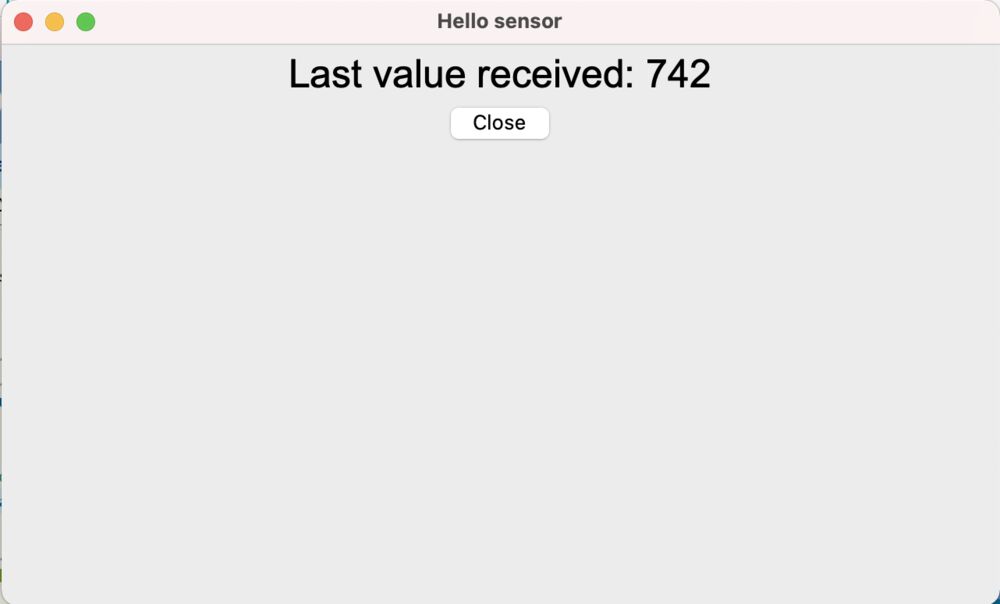
Trying the python hellosensor provided by Ivan.
Got a missing module first off, so:
pip3 install tk
Followed by:
python3 hellosensor.py
Traceback (most recent call last):
  File "/Users/ees609/Downloads/helloworlds_guis-master/python/hellosensor.py", line 11, in <module>
    from tkinter import Tk, Label, Button, StringVar, Frame
  File "/opt/homebrew/Cellar/python@3.9/3.9.10/Frameworks/Python.framework/Versions/3.9/lib/python3.9/tkinter/__init__.py", line 37, in <module>
    import _tkinter # If this fails your Python may not be configured for Tk
ModuleNotFoundError: No module named '_tkinter'
still got an error, apparently python need to be configured to make use of tkinter, so:
brew install python-tk
after seeming to upgrade almost everything on my system:
Traceback (most recent call last):
  File "/Users/ees609/Downloads/helloworlds_guis-master/python/hellosensor.py", line 12, in <module>
    import serial, sys, time
ModuleNotFoundError: No module named 'serial'
once more unto the breach…
pip3 install pyserial
We seem to be there finally, lets run it against the port that has our board attached:
python3 hellosensor.py /dev/cu.usbserial-AB0MKVTQ
Other examples, some notes:
Ivan also introduced the group to a couple of other relevant UI building tools.
Blynk
Blynk is an IoT platform offering to connect devices and wrap the data they produce in a ‘no-code’ application environment.
MIT App Inventor
App Inventor is another ‘no-code’ using a code block interface to produce applications.
Comparison
Both these frameworks allow you to produce applications on sophisticated phone hardware without needing to know sophisticated coding tools. Hiding the complexities of the native coding environments, cross compiling from a simpler description of your application.
The examples that I’ve produced above require programming and an understanding of the environment that you’re coding in. Though they still offer an abstraction over the true complexities.
To do something similar at the bare metal you might consider looking at something like openFrameworks