4. Computer-Controlled Cutting
This week: - linked to the group assignment page - Explained how you parametrically designed your files - Documented how you made your press-fit kit - Documented how you made your vinyl cutting - Included your original design files - Included your hero shots
Summary
This week we made use of the Roland GX-24 to cut some paper to form a 3D object that if you squint could be called an assembly kit.
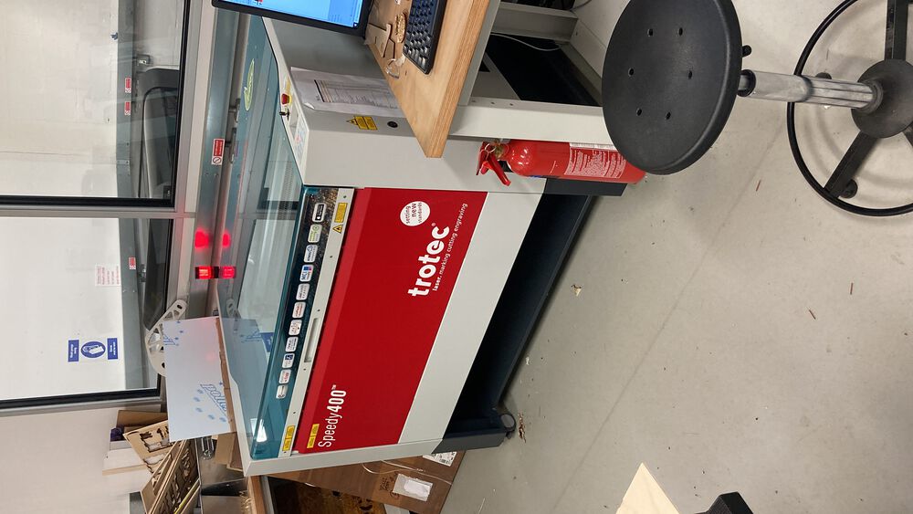
We also used a Trotec speedy 400 to cut card to test out a sculpture contruction kit.
We also did some characterisation of the laser to discover the kerf.
Group Assignment ‘21
Group Assignment ‘22
Reflection
These cutting tools are a great for very quickly tranlsating ideas onto accurately cut parts. With a little thought they are also not limited to 2D.
Tools and Software
Trotec Speedy - Pontio fablab laser resources Roland GX-24 - Pontio fabalab vinyl cutter resources
FreeCAD CorelDRAW - (used to drive our lasers, compile the final tiled construction set) Roland CutStudio - (used to drive the Vinyl cutter) Adobe Illustrator - (file conversion in this instance)
Files
Tetrahedron freecad - half_tetra.FCStd Tetrahedron svg - half_tetra.svg Tetrahedron dxf - half_tetra.dxf Tetrahedron eps - half_tetra.eps Construction Set freecad - construction_set.FCStd Construction Set dxf - construction_set.dxf
A Robot Knife
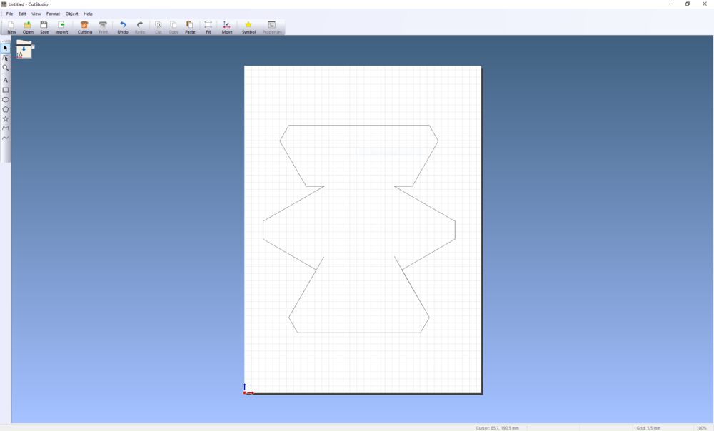
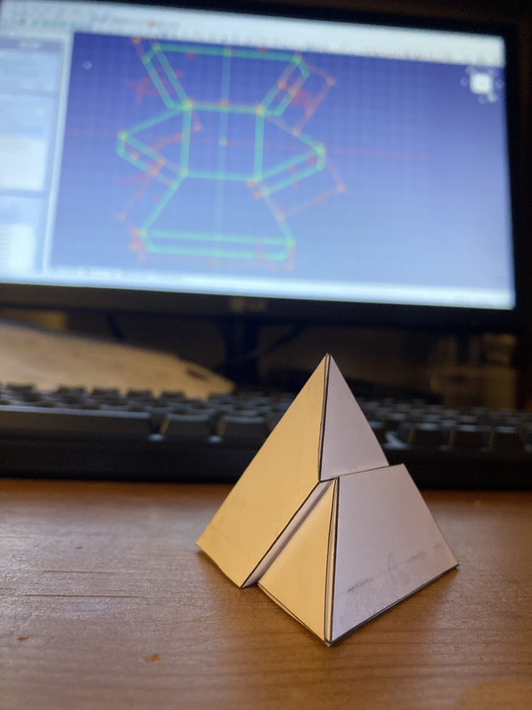
Familiar with using the vinyl cutter for regular 2D applications I decided to use the tool to create a 3D form. A simple puzzle part in the form of a half Tetrahedron that mates with an identical part to form a full Tereahedron.
I was given a puzzle much like this as a child:
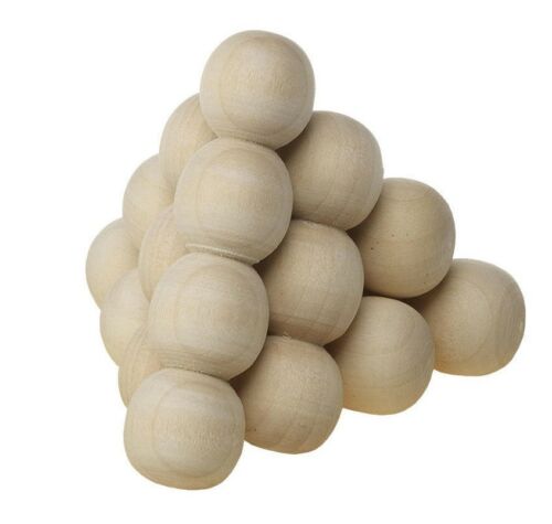
the symetry of the thing was always fascinating. It also interesting to work out that in a shape made of triangles there’s a perfect square in the middle.
Designed as a parametric sketch in freeCAD. Exported with the TechDraw workbench to output a .svg
Vinyl cutting, the basics
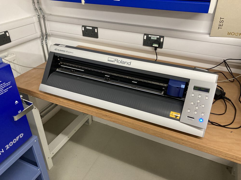
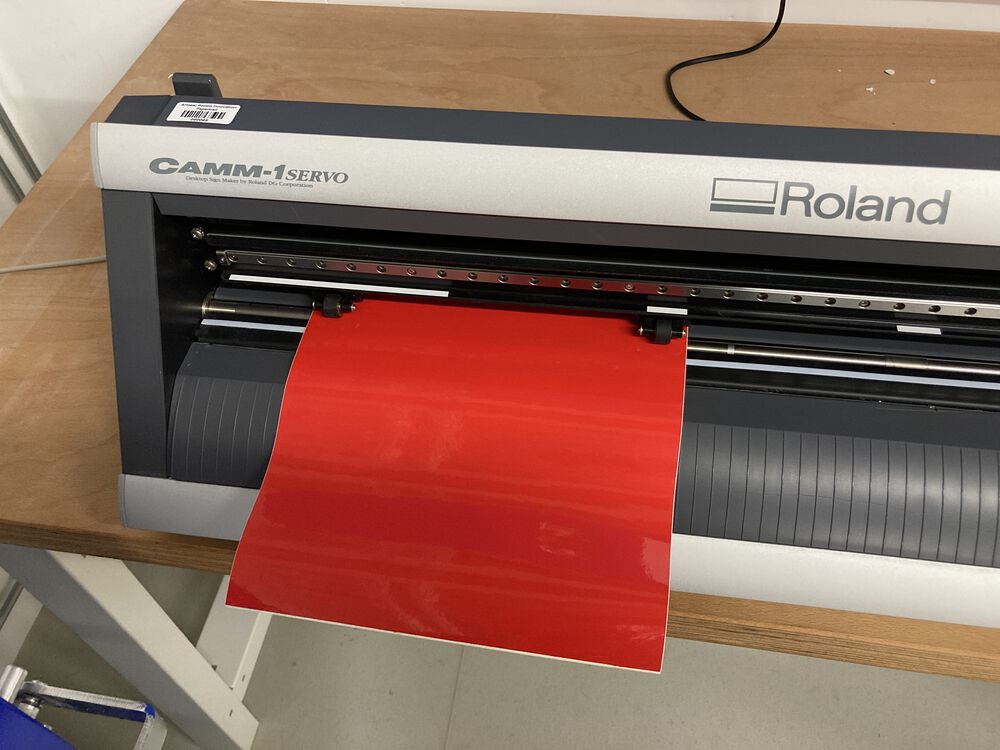
The Rolan GX-24
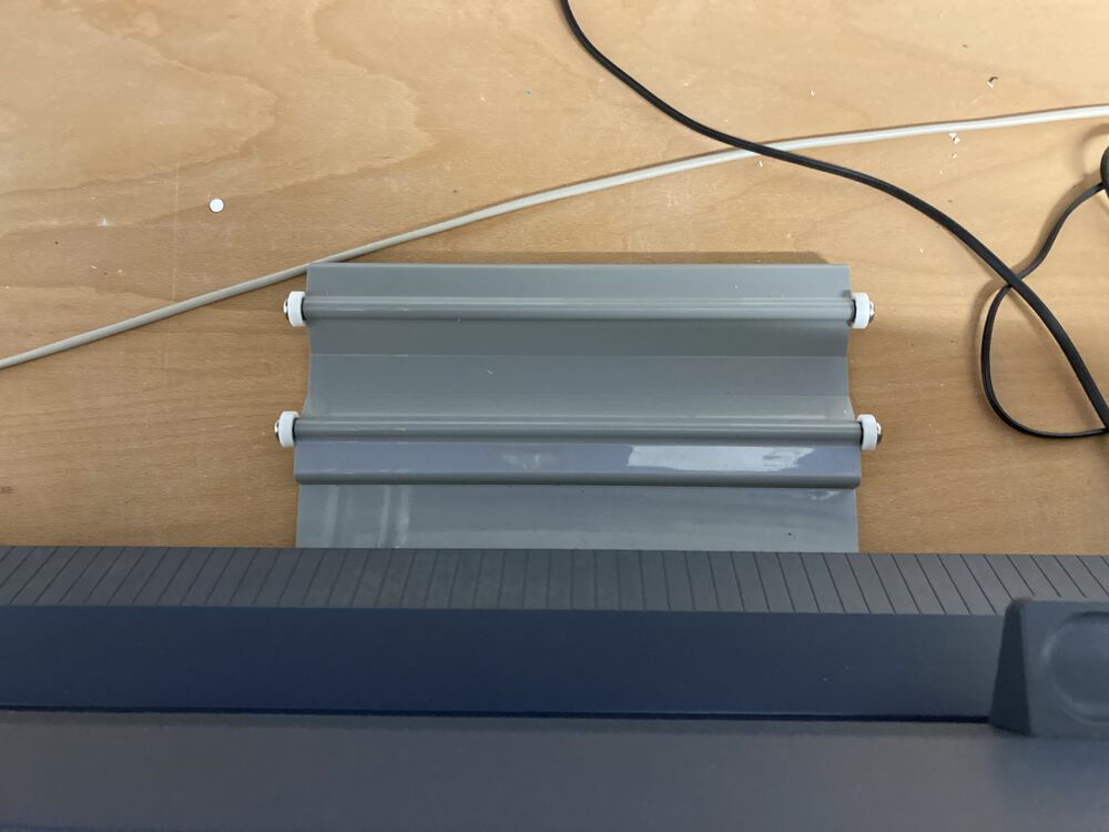
Material clamp at the back, this lifts and pushes down the pinch rollers
Rollers for rolls of material that get fed in to the machine from the back
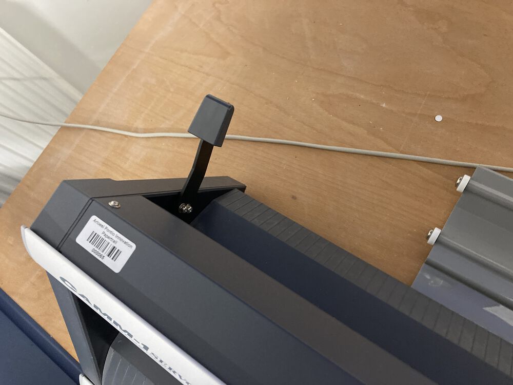
Pinch rollers need to stay in a spot marked by a white bar
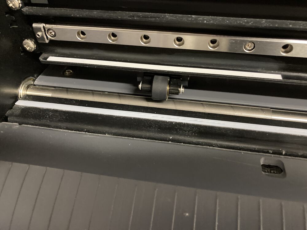
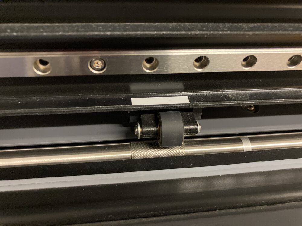
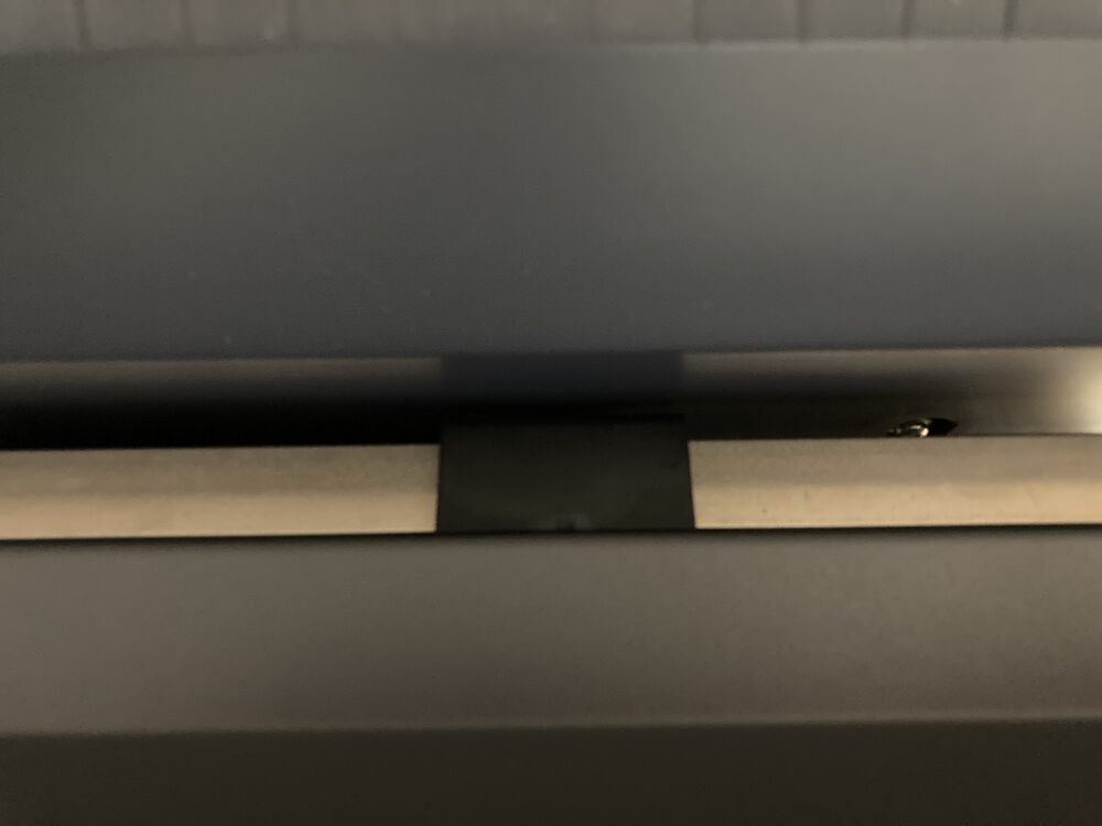
Move them by reaching behind the machine and locating the rectangle at the back, the will cam lock if you do it from the front
The left hand roller has a lot more flexinility thatn the right, set the right first when adding material
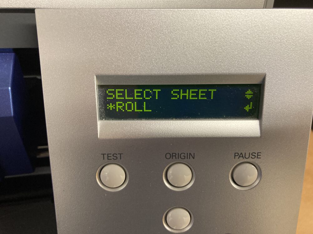
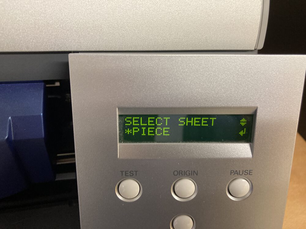
Select type of material
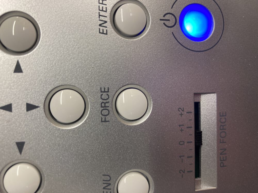
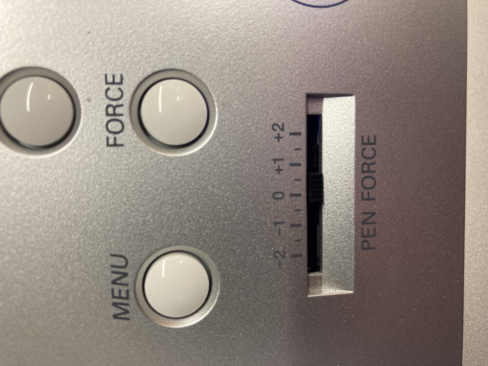
Hold down the test button to check your settings
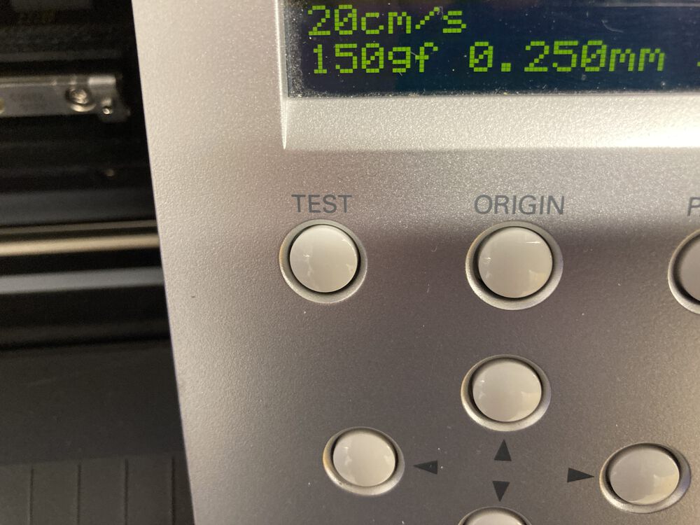
If it’s not cutting cleanly tewak the force settings
Run your job from software that will export a suitable vector via the print driver.
CutStudio
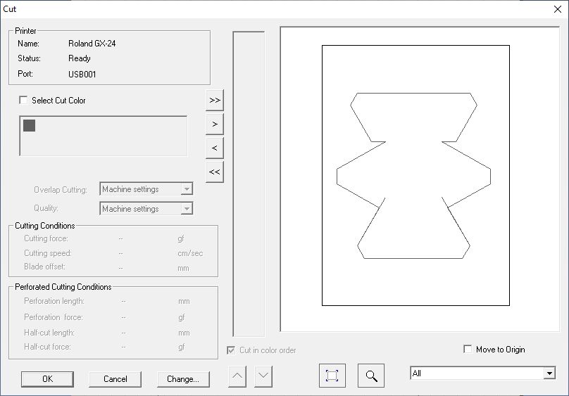
We use cut studio, a very simple piece of software to drive the Vinyl cutter.
Key parts to remember in relation to cutting.
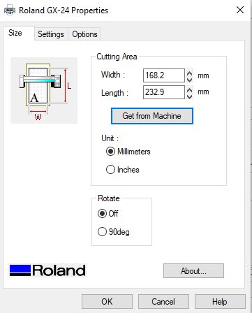
Once you hae your material loaded as directed above, Cutting setup can be accessed to retrieve the measured width of the loaded material, this will update your canvas.
CutStudio has a limited number of vector file formats it will import. From Illustrator we export either a .ai or .eps, saving the file in the oldest verion of the format possible Illustrator 3. (eps inluded above)
For cutting we’ve removed the crease lines.
When your ready, cutting is much like sending something to the printer.
FreeCAD Spreadsheets
This simpler form gives us a chance to look at the basics of parametric design in FreeCAD.
It starts with the Soreadsheet Workbench, where we create a new Spreadsheet. This can be renamed something useful like Parameters, or param if you like to type less (par if you really like to save disk space).
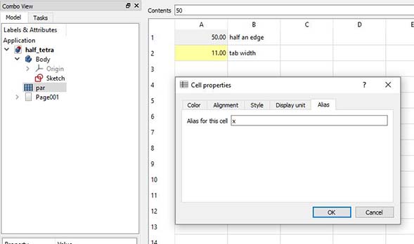
With the pread sheet open we’re going to fill generic cells with two types of content. Labels make the spreadsheet human readable, when you come back to make changes you need to know what your numbers mean. Numerical cells will be associated with an Alias to turn them into parameters. For a core task this seems to be a roundabout procedure for each cell that you want to act as a parameter. However, it’s achieved with a right click on the cell to access the Properties, then the last tab in the dialog gives you the Alias. Choose an alias that will make sense when you reference it later.
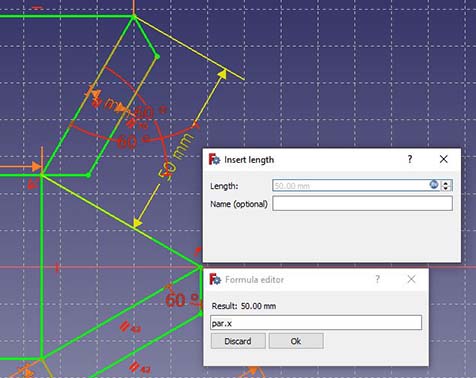
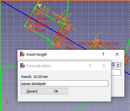
With the parameter prepared, we return to sketching. The parameter is used when we set a dimension in our sketch. Instead of entering a value directly we hit the little circular icon on the right hand side of the data entry cell and enter a reference to our parameter, start with = add the name of the spreadsheet, a full stop and then the name of the desired parameter. All the names will autocomplete once you get them started. Repeat for all parameterised dimensions.
Exporting for the laser cutter
To produce .svg files suitable for our vector driven machines, from our sketches we can use the TechDraw Workbench. Before we do we need to make sure that we are looking at our object to export straight on. Use the Navigation Cube to make sure the view is normal to the plane of interest.
With the TechDraw Workbench active we need to create a new drawing, these normally come with a frame but you can open a custom blank.
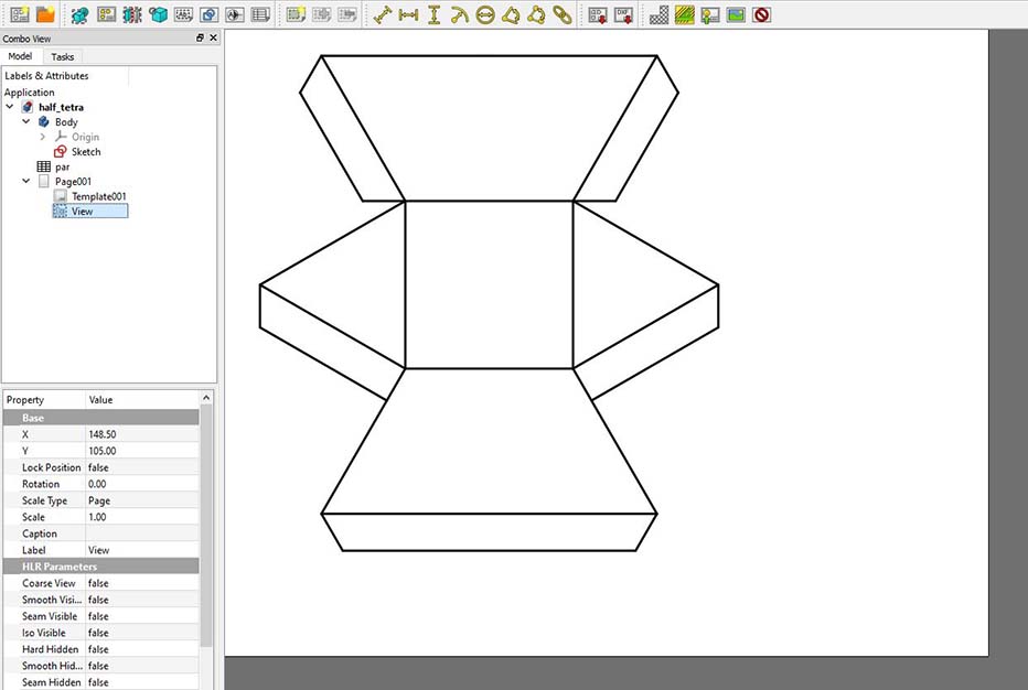
Now we need to select the Body of our sketch in the Model Tree and add a View to the drawing. If we were preparing a technical drawing we would be able to add dimensions, but for exporting just the lines we want as little visual clutter as possible. Clicking on the ToggleFrame will get rid of some of tat clutter and leave behind clean lines.
You can now export this drawing as a .svg file for use with either of our cutting machines.
Running the job though the Vinyl Cutter
The Tetrahedron was designed off site. To validate the file we ran a test with desktop printer and scissors.
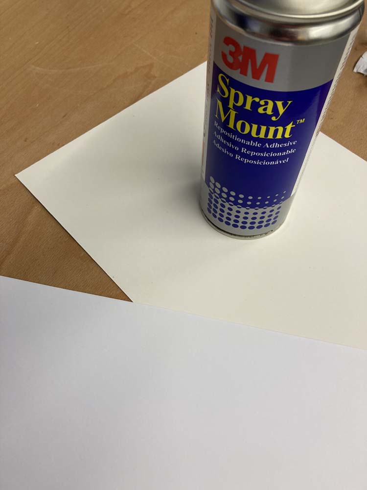
 Once we had access to the workshop we ran off a copy with the GC-24. To begin with our thin stock material needs a backing for the vinyl cutter to be able to grab and move it. So a we mounted some copy paper to some card with some low tack spray adhesive.
 We used the standard Roland CutStudio to run our file though the machine.
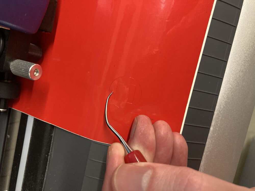
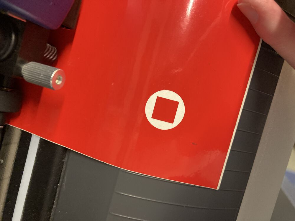
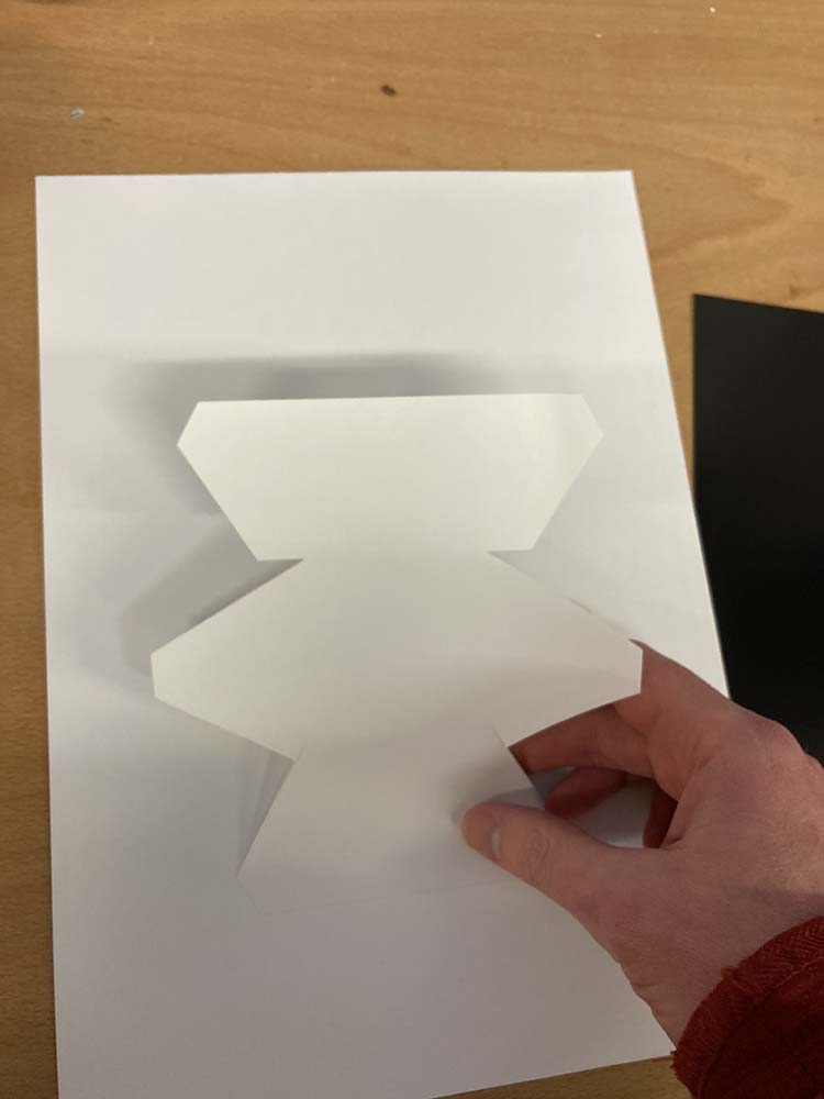
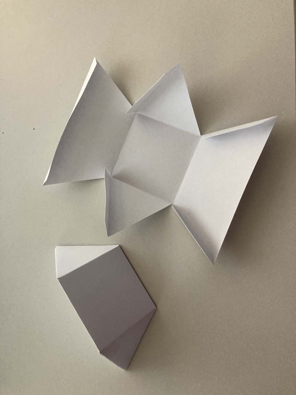
In the image below, lifting the cut form, from the tacky board after cutting.
We used the standard Roland CutStudio to run our file though the machine.
In the image below, lifting the cut form, from the tacky board after cutting.
 We didn’t have time to characterise a separate creasing process. So, post cutting, the tabs were creased by hand.
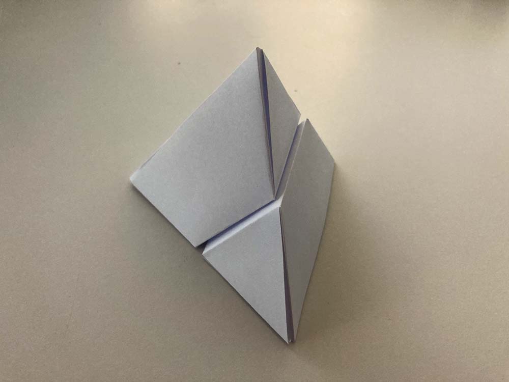
 Here we see two identical parts assembled
Laser
We used a Trotec Speedy 400 for this work, capable of taking a card sheet 1000x600mm
Safety
Things to think about.
- Don’t cut materials that will give off hazardous chemical or particulate matter, eg PVC gives off Chlorine if you try to cut it
- Cut with the correct power and speed setting for your material. Cutting paper with thick ply setting could start a fire
- Don’t try to circumvent the safety features of the machine, eg door interlocks
- Don’t leave the machine running on it’s own, even it you’ve cut the exact same job a hundred times before, you can’t guarantee perfect materials or perfect operation, you could burn your building down
- Let the extraction clear the cabinate of residual smoke before you open it
- make sure the extraction system if operating correctly
Operating basics
We assume that an operator will receive full training before using the machine.
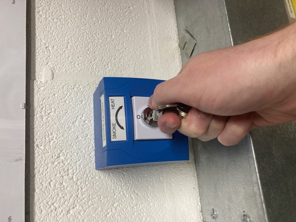
Before we start cutting we set the smart smoke detectors in the room to heat, from their normal setting of smoke.
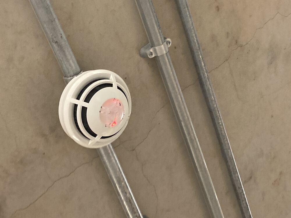
Detectors will show a red light in the correct mode
The laser has a main cabinet
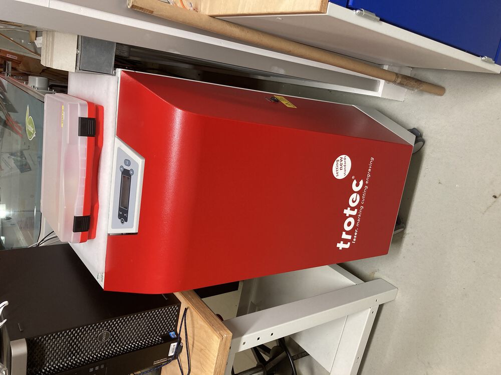
and a local extractor
Use the key to power up the machine
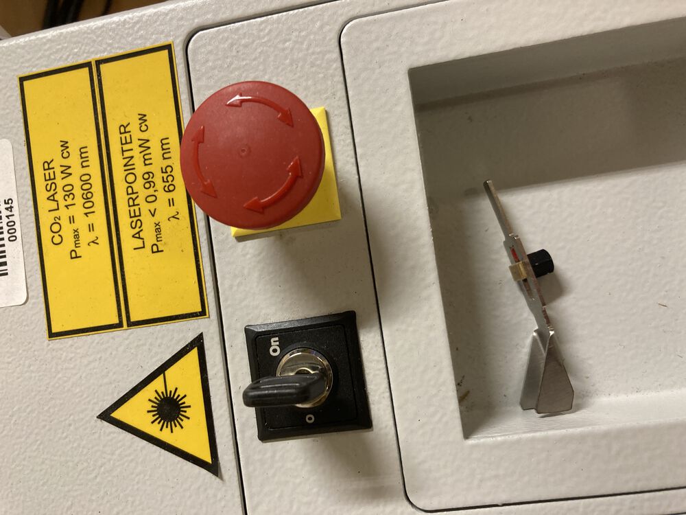
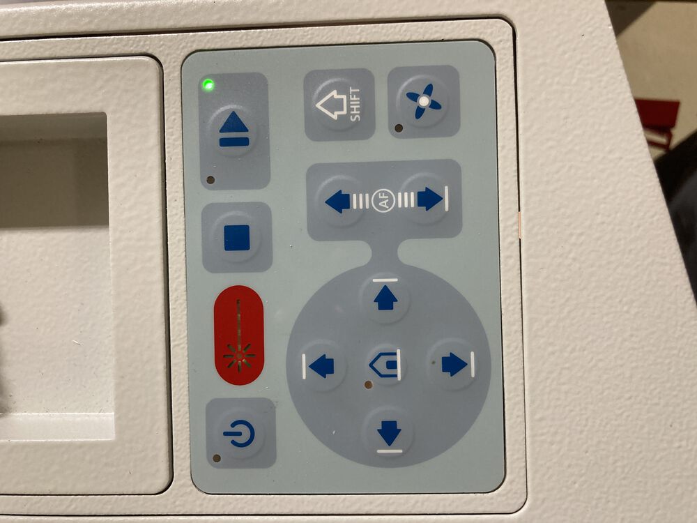
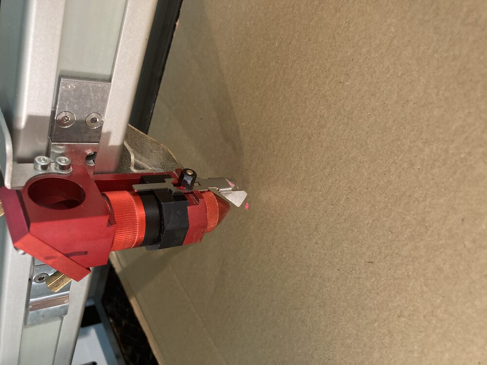
the control panel allows us to move the head and the bed to focus the material
we use a manual focussing tool, bring the material up till the tool falls off the head
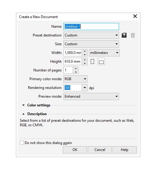
Open a new document, by convention at the full size of the bed, and import you artwork
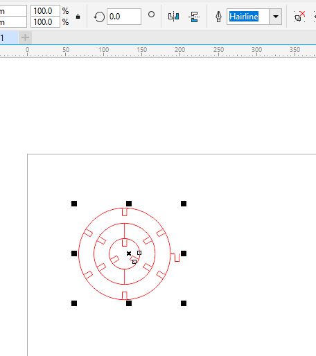
for simple cuts, all lines need to be ‘Hairline’ thick and red. Engraves we set to black
Make sure the correct material setting are selected from the library
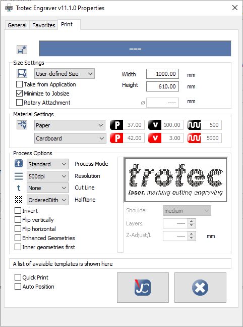
Once you hit print, your work is passed onto Trotec Jobontrol where we place it onto the plate, potentially snapping it to the cursor representing the laser head and hit play to cut.

Characterising
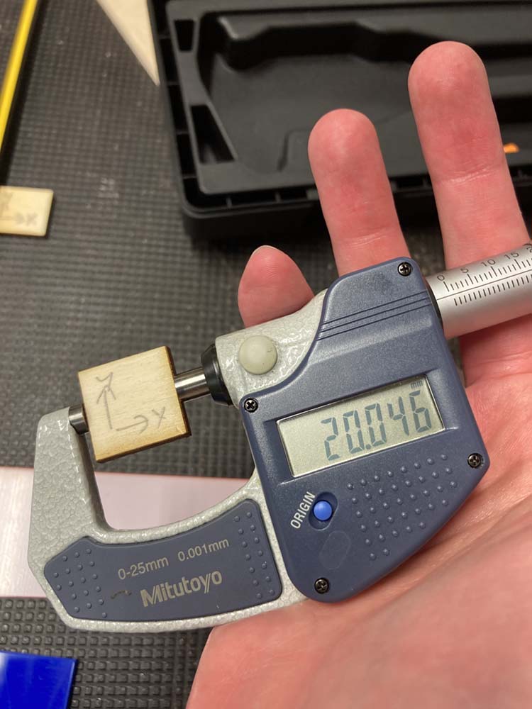
Having measured the kerf during our characterising of the lasesr. Here we are measuring again after compensating for Kerf on a 20mm sqaure.
Sculpture Construction kit
Inspired by Tazos like many of us, but wanted to give it a twist.
Aimed to get 100% material coverage and a variety of parts.
Parametric design in FreeCAD was done as described above, but with a few more dimensions fixed in the spread sheet.
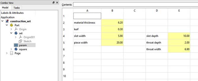
The width of the rings was parametric, as was the thickness of material accomodated by the joints. Also parameterised was the throat of the slots to make assembly easier.
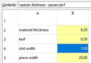
In common with regular spread sheets, we can derive our values with equations referencing other cell values. Here we can see that the slot width is in fact a calculated value made up from the material thickness and the kerf of the laser cutter:
Here we have an image of the construction set under construction in FreeCAD
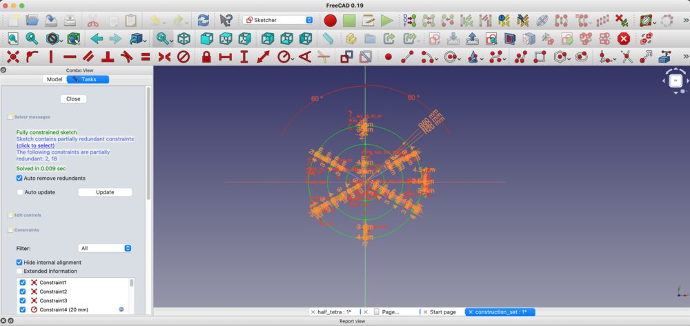
The sketch is mainly circles. We can see a lot of constraints on the sketched out slots. This was before I found out about pattering repeated structures.
Like any other sketch, use the basic line tools to form your shape, then add constrints till it is fully constranined and meets you needs.
Cut on a Trotec Speedy 400
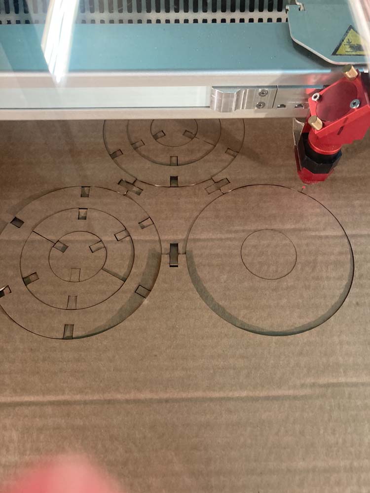 The construction kit was designed to fill the material, with nesting circular pieces and triangles using up the space between. All nested, we have almost completed material coverage, where the only waste is the slot interior.
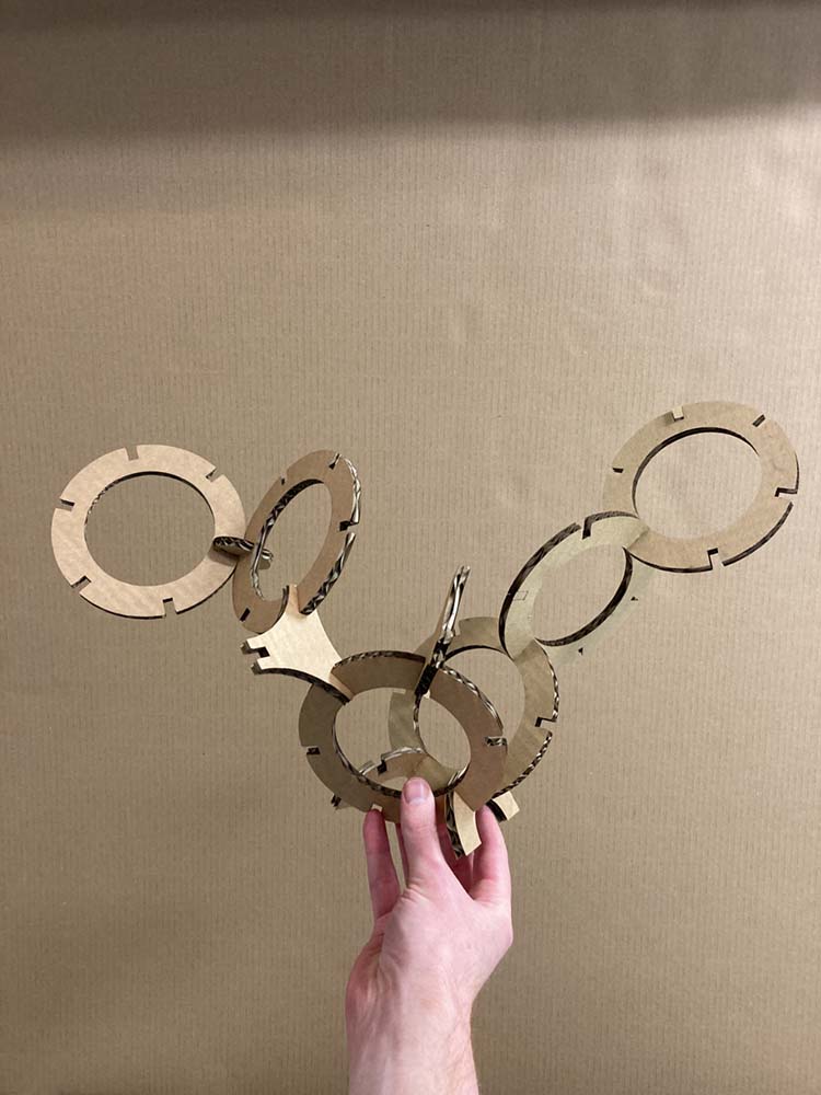
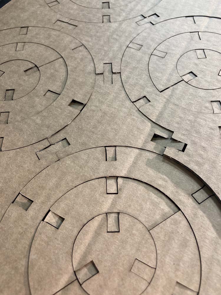 Nice joints, slight throat to the opening to ease mating
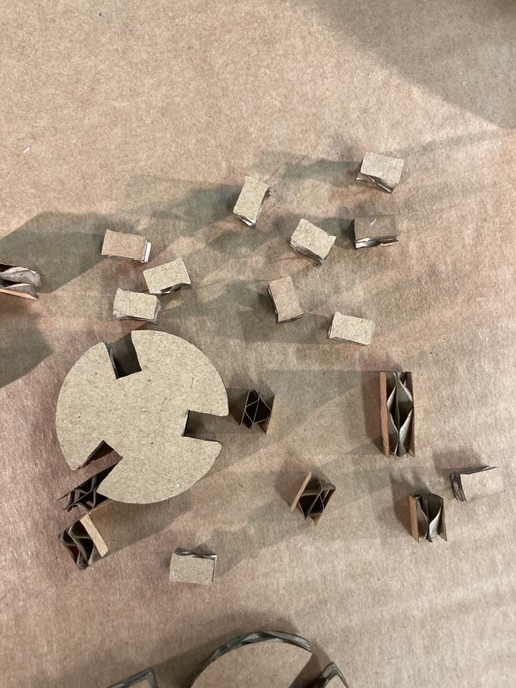
 Variety of parts
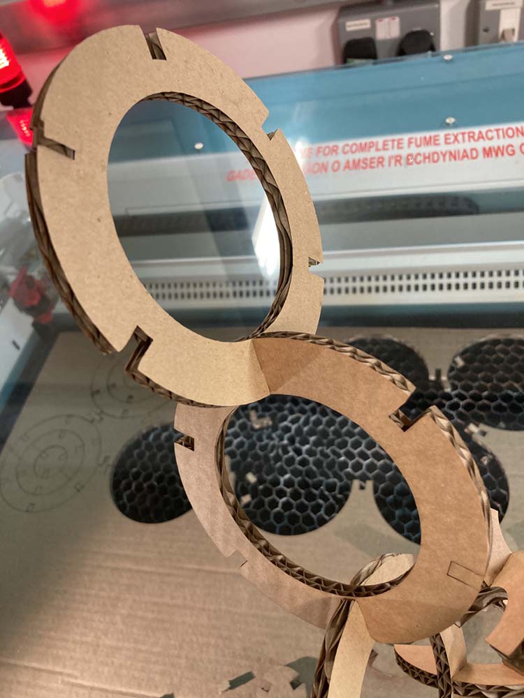
 This bit slight fail, slots meet at the centre, does not take into account width of sheet, need to tweak the parameters
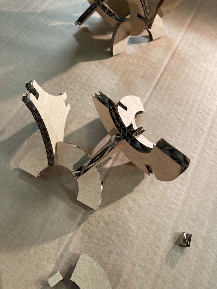
 Free form sculpture
Changes
Next time we need to make sure that the diameter of the centre circle accomodates parts meeting at the centre.
Also make use of the repeating Polar pattern to cut out the slots. The current design is sufficiently parameter driven to accomodate changing material thickness, however we can’t easily change the number of slots.