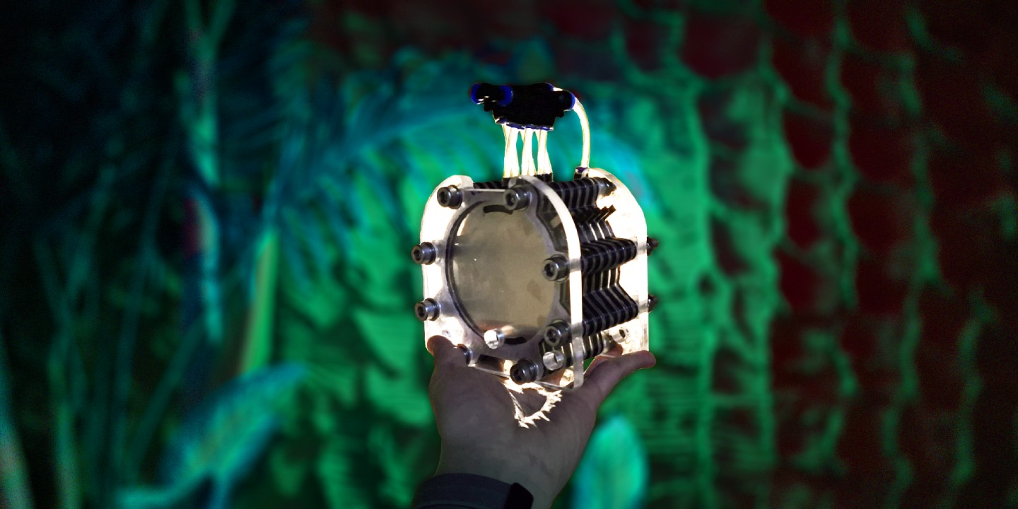
Separated HHO Generator
Electrolysis is a chemical reaction process that occurs by passing electric current through a solution. It has many practical application such as electroplating, electrorefining, producing many types of chemical compounds, etc. In this article we will be exploring at designing a generator that could produce hydrogen and oxygen from water through electrolysis process.
Currently, the best electrolysis method to split water to hydrogen and oxygen is by utilizing PEM (proton exchange membrane) generator. It capables of generating high-purity hydrogen gas from deionized water, making it safer and more efficient. Unfortunately the best catalyst option known at the moment for this type of generator is platinum, resulting in a very extremely high price tag that is out of reach for many.
The other alternative for generating hydrogen from water is through alkaline electrolysis. When you search for a DIY hydrogen generator - on Google or YouTube, most of the results shown will be an alkaline based and mostly categorized as HHO generator. It named that way because the hydrogen gas produced at the cathode and the oxygen gas produced at the anode are mixed together creating a HHO gas mixture. This gas is highly explosive, making it really dangerous to be stored in any amount.
With PEM generator, the membrane itself prevent the two type of gases to mix together while still allowing the proton to pass through. Unfortunately, There are no easy way to achieve the same thing with alkaline electrolysis. However, there are multiple attempts that shows promising results to separate the gas mechanically as best as possible without obstructing the electrolysis process too much.
Design
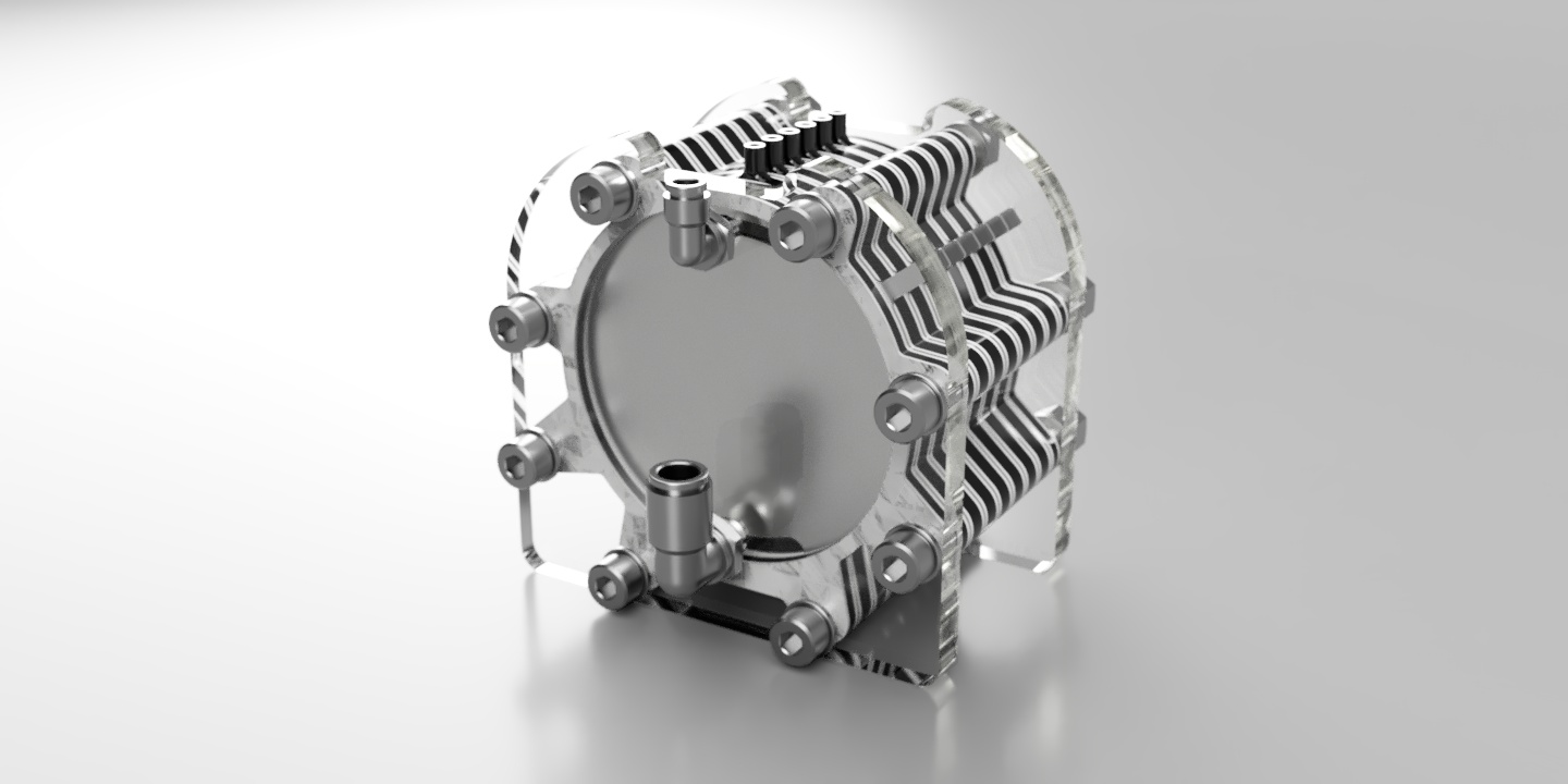
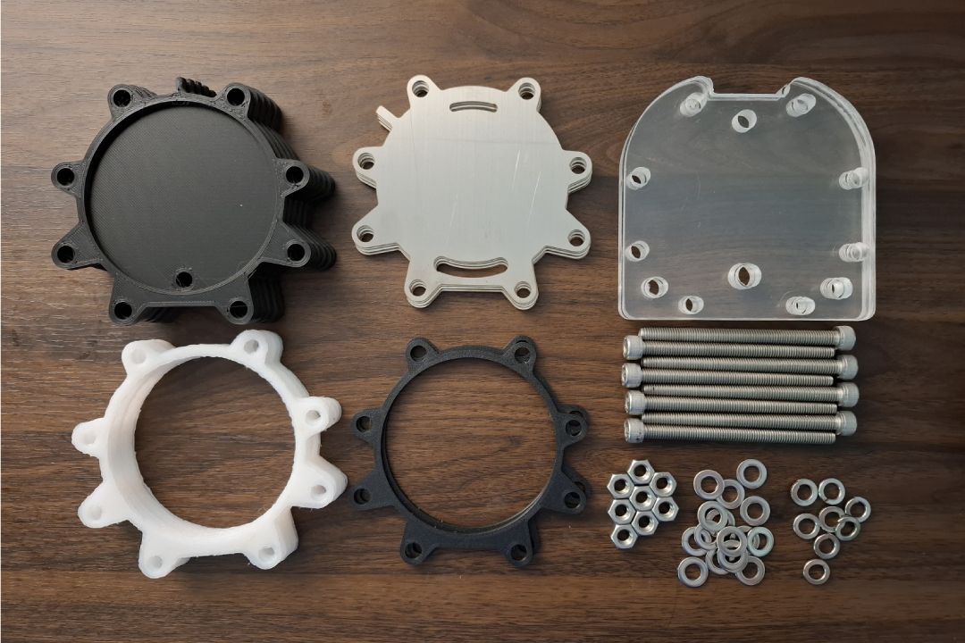
We will only focus on the design and fabrication aspects of the generator in this article and will discuss more about the electrolysis utilizing the generator on later date. This design has multiple set of components listed below:
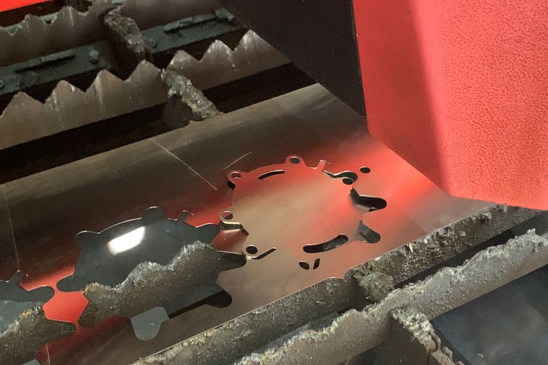
- 7 plates of 1 mm electrodes
- 2 set of 3 mm spacers
- 16 set of 1 mm gaskets
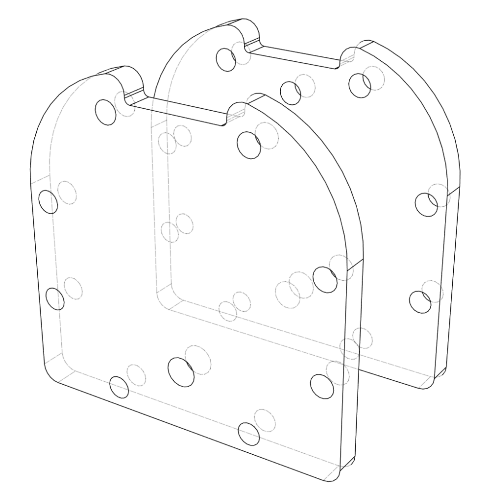
- 1 pair of 10 mm acrylic frame
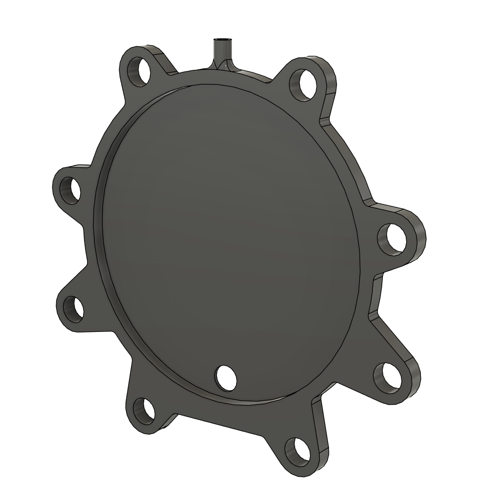
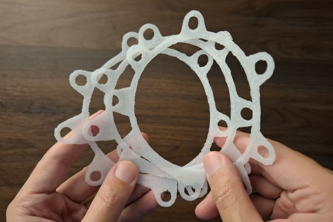
- 6 set of separators
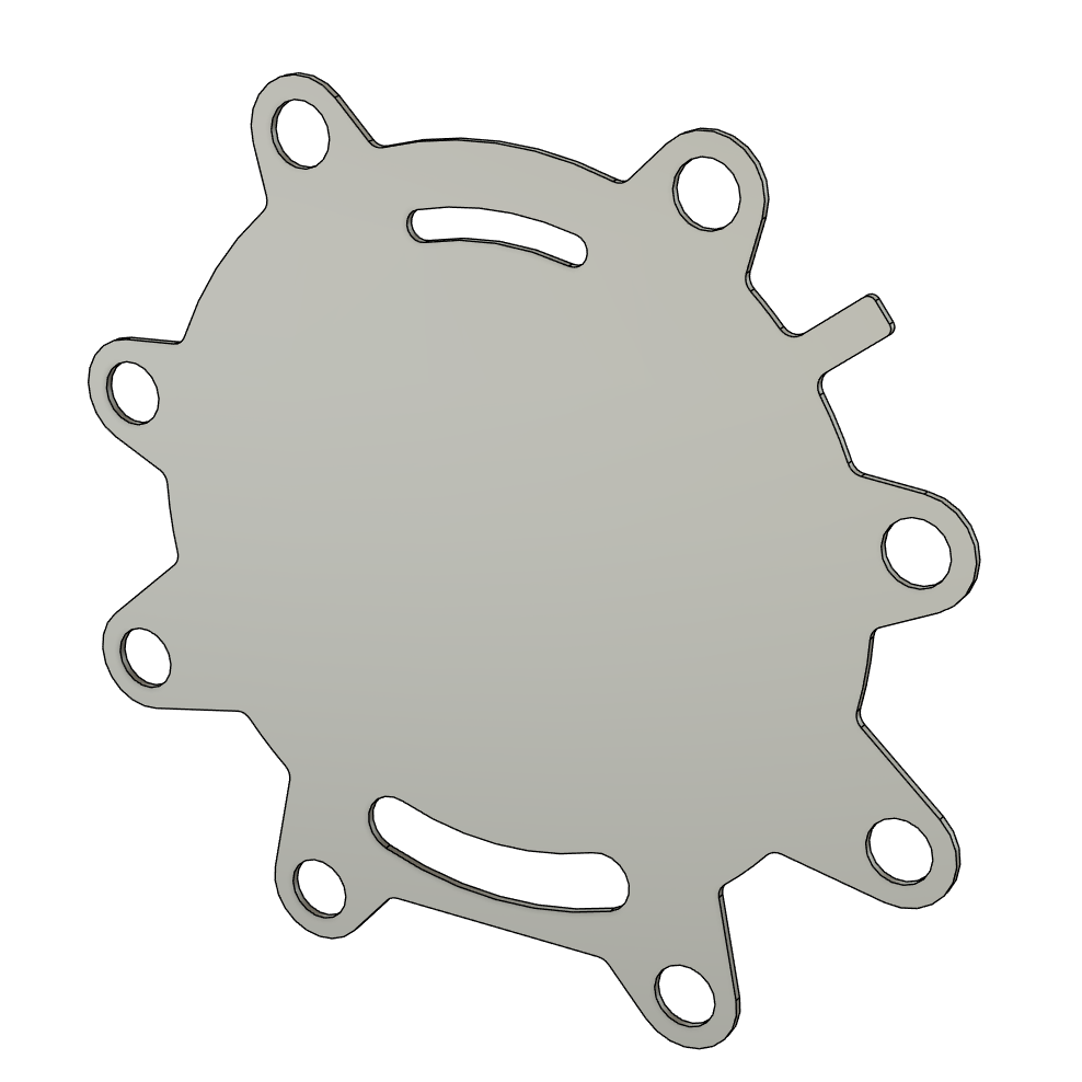
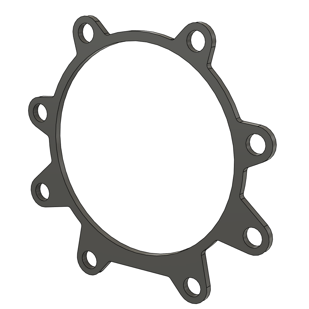
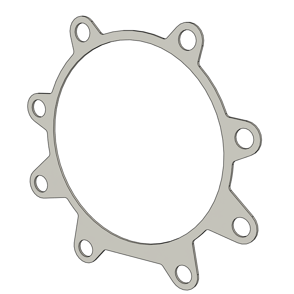
All of those components shown above were simply designed by extruding a sketch profile. The separator requires few more extrude operations creating the geometry for funneling the gases generating by the electrodes. It has an opening at the lower area to let the liquid solution still be connected to all the cell. This still has potential to let the gases to be mixed but should have lower the amount significantly. A possible improvement for the future is adding nylon mesh to cover this opening.
This design is heavily inspired by a particular generator from a YouTube video by Inventive - Water Fuel. The changes made are the addition of mounting holes to the electrodes, separators, gaskets, and spacers; and changing of electrode's connector from screw to a spade terminal. Both changes were made to make the assembly process easier.
Fabrication
With the exception of the separator which will be 3D printed, all of the components can be fabricated using a computer controlled cutting operation. Below are the breakdown of each components fabrication process.
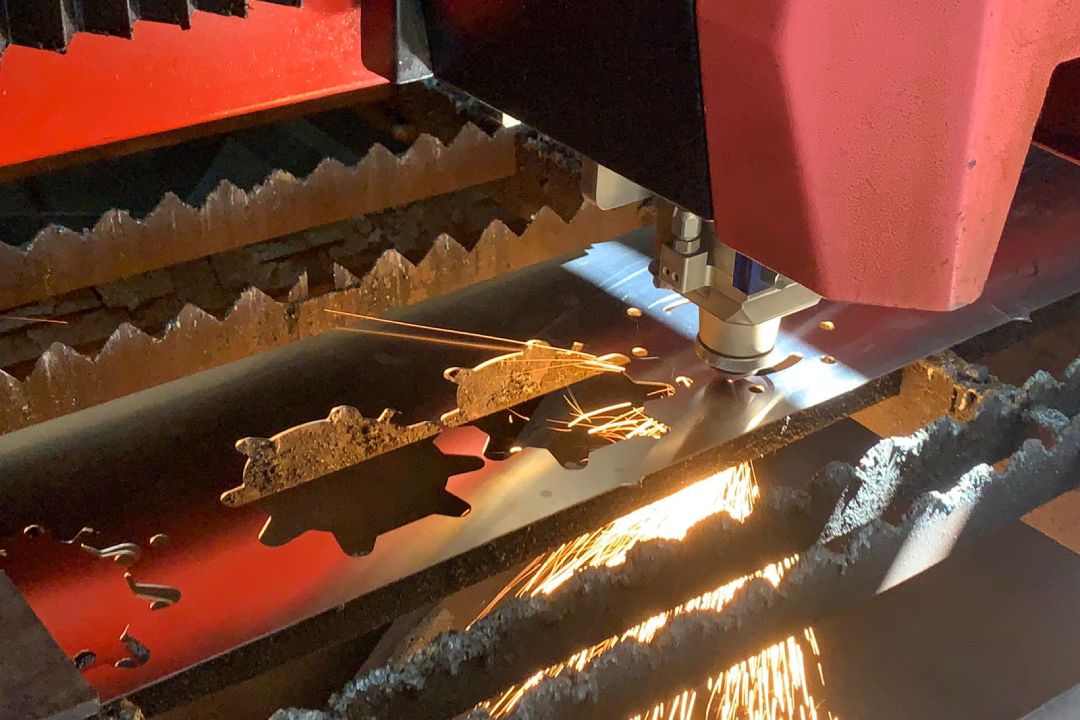
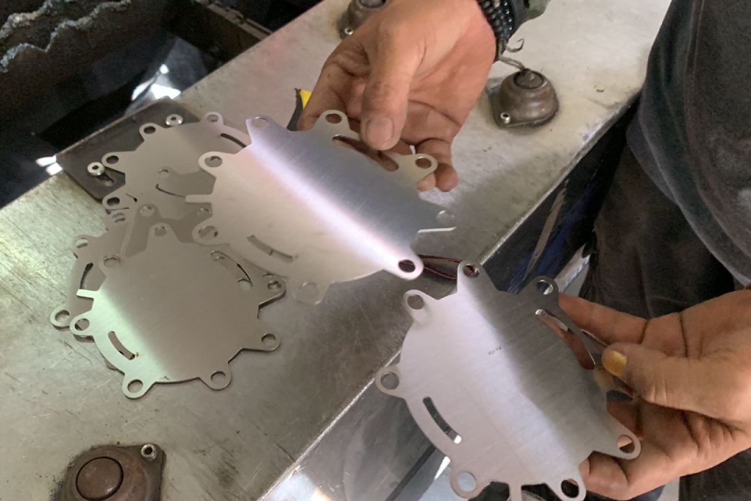
Electrodes
Not any metal can be used as electrolysis electrodes. This process essentially trigger an oxidation process on the anode which will corrode it and the cathode too to lesser degree. Unfortunately, the best option for electrode is also platinum. However, although not as effective, stainless steel 316 which is much more affordable can be used as an electrode.
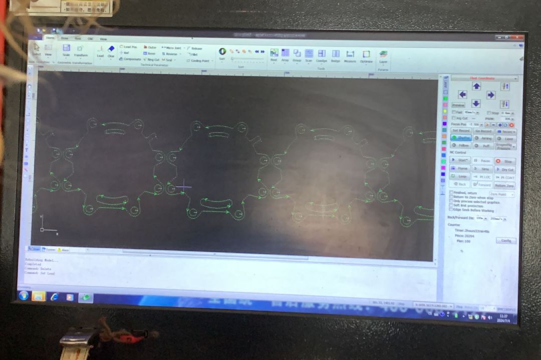
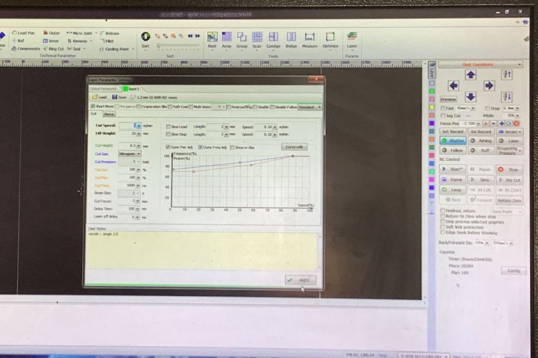
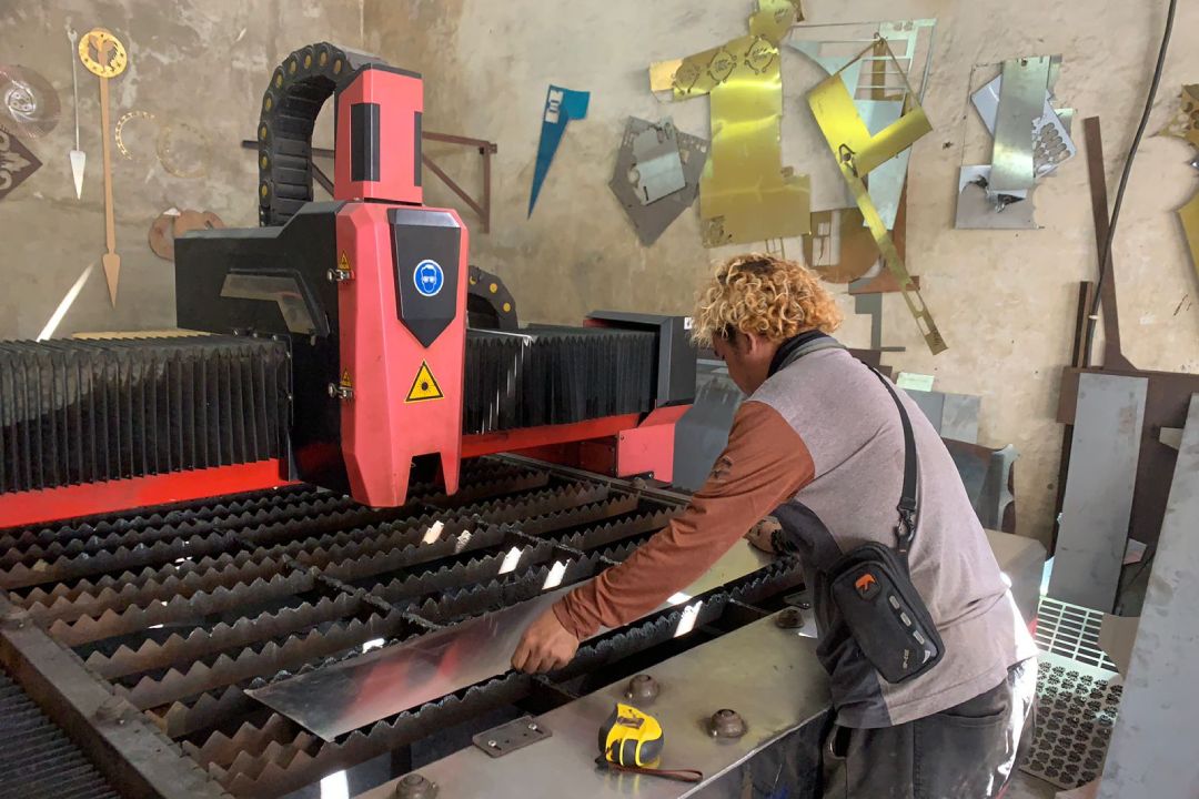
To cut the stainless steel, we need to use a fiber laser cutter. Exercise more caution when working with it because it is a much more powerful laser compared to a diode or CO2 laser. These machine usually not equipped with an enclosure, it is advisable to use appropriate eye protection. However, the principle and the workflows are pretty much identical to CO2 laser cutter we've seen back in computer controlled group assignment. Below are the short summary:
- Import your 2D file
- Set feed speed and power based on the material you are cutting
- Sort the cutting order when necessary
- Place material on the cutting bed
- Check the perimeter of the cutting operation
- Proceed with the cutting operation
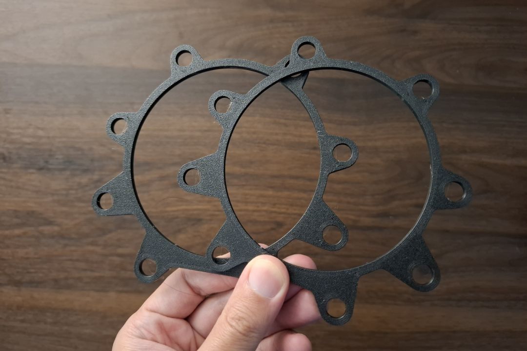
Separators, Spacers, and Gaskets
3D print the separators using PETG or even better using ABS. PLA is not recommended because it could potentially got soften by the combination of alkaline solution and the electrode heating up.
The spacers can be cut out of acrylic sheet, but you can also simply 3D print them. For the gasket we could 3D print the using TPU, though this need to be further tested if it can handle the combination of alkaline solution and heat. Ideally the gasket should be fabricated out of PTFE sheet.

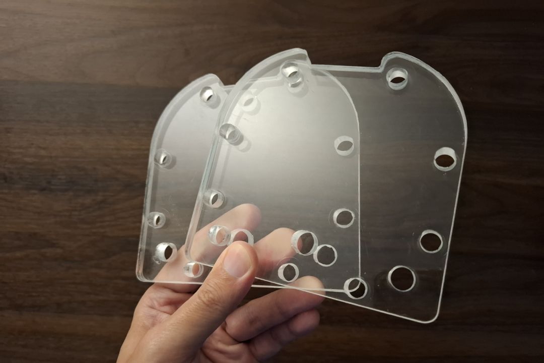
Frames
Cut out both frames from a thick acrylic sheet, 10 mm is recommended because the frames need to be sturdy. It is recommended to cut it using a milling machine because cutting acrylic at that thickness will suffers bigger deviation on the edges.
Though not a requirement, using a clear acrylic will let you see the generator working and may help see if there is any potential issue happening. There are holes on the frames that need to be tapped for attaching some pipe fittings.
Assembly
Beside all the components need to be fabricated, we also need these stainless steel fasteners:
- 8 set of M8 x 90 screw
- 8 set of M8 nut
- 8 set of M8 lock washer
- 16 set of M8 washer
- Electrical tape or heat shrink tube
Follow the steps bellow to assemble the generator:
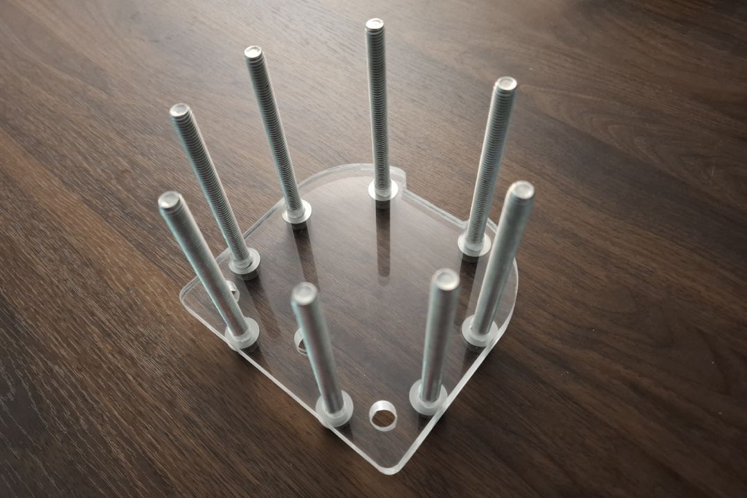
- Start by covering majority of the screws body with heat shrink tube or electrical tape to insulate them from the electrodes
- Put the screw along with washer on all the holes of one of the frame, then laid it down flat with the crew head facing down
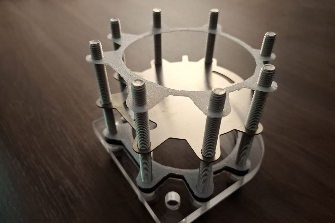
- Align a gasket with the screws and slide it down to the frame. Align the flat side of the gasket to the bottom of the frame
- Follow it with a spacer, a gasket, an electrode, and another gasket. Keep in mind to align the bottom flat side of all the components
- Add the separator the same way but keep in mind which side of the separator is facing up or down. The subsequent separators need to face the same way
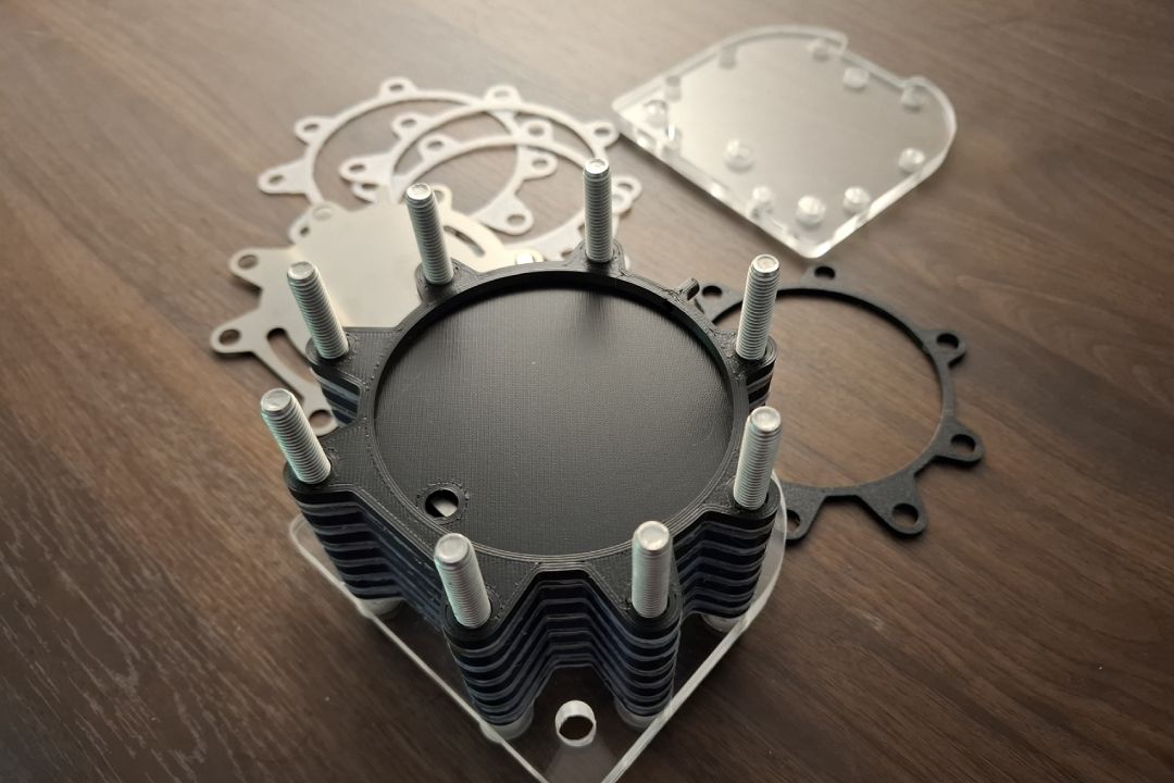
- Repeat with the rest of the components with the same order: gasket → electrode → gasket → separator → gasket → electrode → .... → electrode → gasket → spacer → gasket → frame
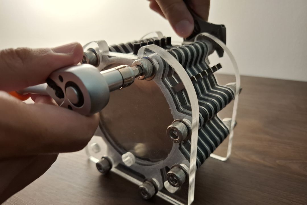
- Add a washer, lock washer, and nut to all the screws
- Fasten all the screws and the nuts incrementally in a diagonal pattern until all of equally tightened securely