3D Printed Ball Joints
Ball joints are mechanical bearings that fit together to allow rotating and pivoting motion in mechanical applications. Sometimes also known as ball and socket joints or axial joints, they consist of a component shaped like a ball, which is housed inside a spherical cavity similar to human shoulder and thigh joints. They are used in many machinery applications, such as automotive suspensions.
This post is about how to create small-scale 3D printed in-place ball joints. They can be used for small-scale mechanical contraptions or even an RC car, though the latter might require more robust materials to withstand more mechanical stresses.
Modeling The Ball
We are going to model a multi-component object. Let's start by creating a new component and naming it Ball. This component is relatively simple to model and only requires two steps:
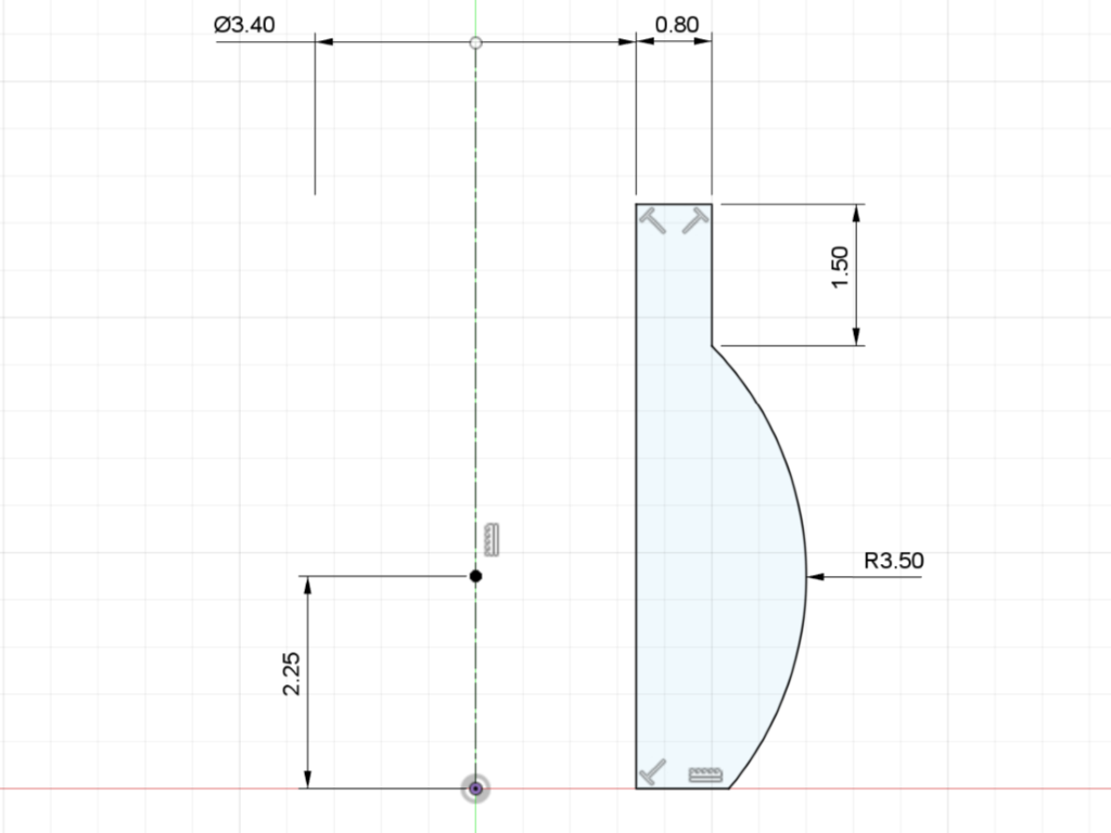
- Within the newly created component, create a sketch on the XY plane. Sketch it as shown in Figure 1 and then finish your sketch.
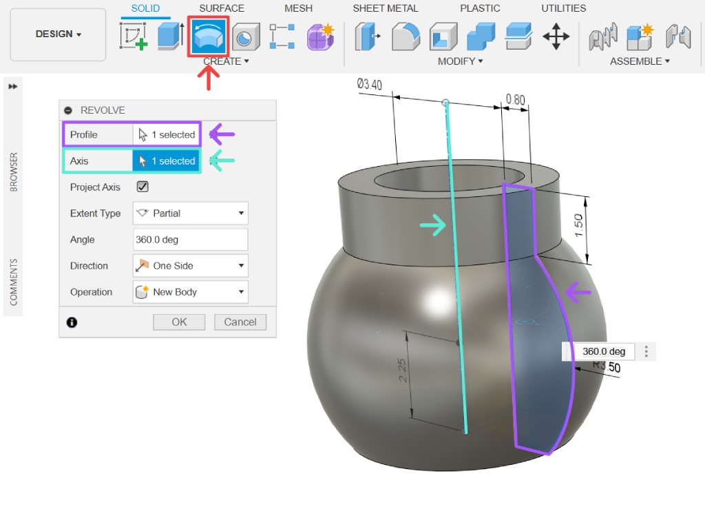
- Utilize the revolve tool. Select the profile we sketched in the previous step, and then select the Z axis as illustrated in Figure 2.
Modeling The Socket
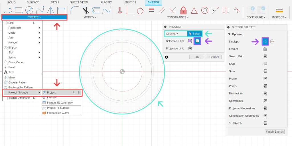
Create a new component and name it control arm. We can utilize parametric modeling by referencing the ball component first. Create a sketch on the XY plane. Use the project tool (shortcut P), making sure to enable the selection filter for bodies and use the construction line type, then select the ball geometry.
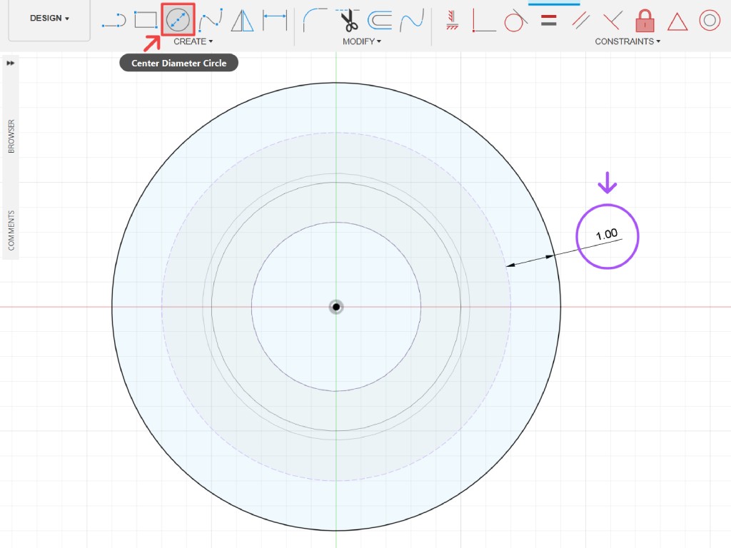
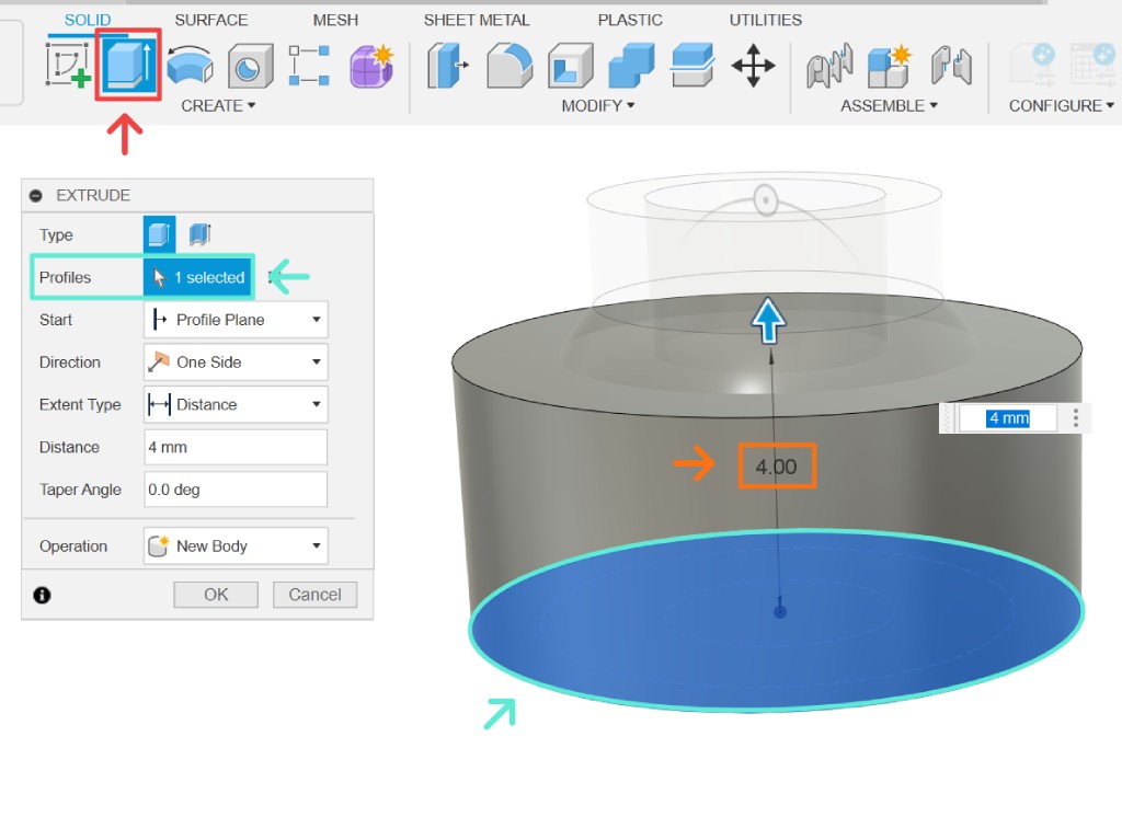
Next, create a circle (shortcut C) concentric with the projected geometry and set the distance to 1 mm, as shown in Figure 3. Once done, finish your sketch, then extrude (shortcut E) the newly created sketch profile, setting the distance to 4 mm, similar to Figure 4."
Now, we need to carve out the socket cavity. Although it's a straightforward operation, selecting the parameters correctly is crucial. Follow the steps below:
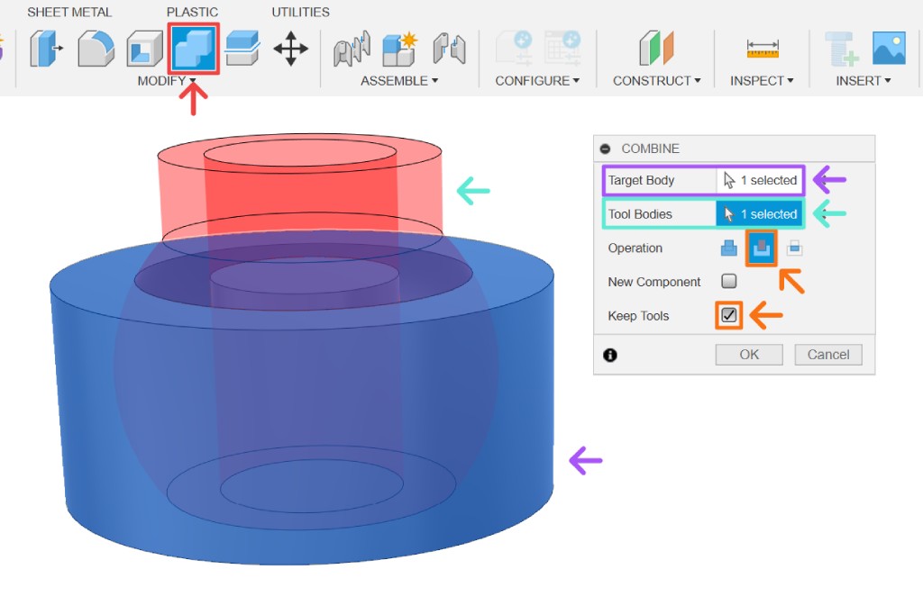
- Select the combine tool in the modify tab, as illustrated in Figure 5. Choose the socket body as the target body and the ball body as the tool body.
- Set the operation to cut and ensure the keep tools checkbox is checked; otherwise, the ball geometry will be deleted. Then, press the OK button or
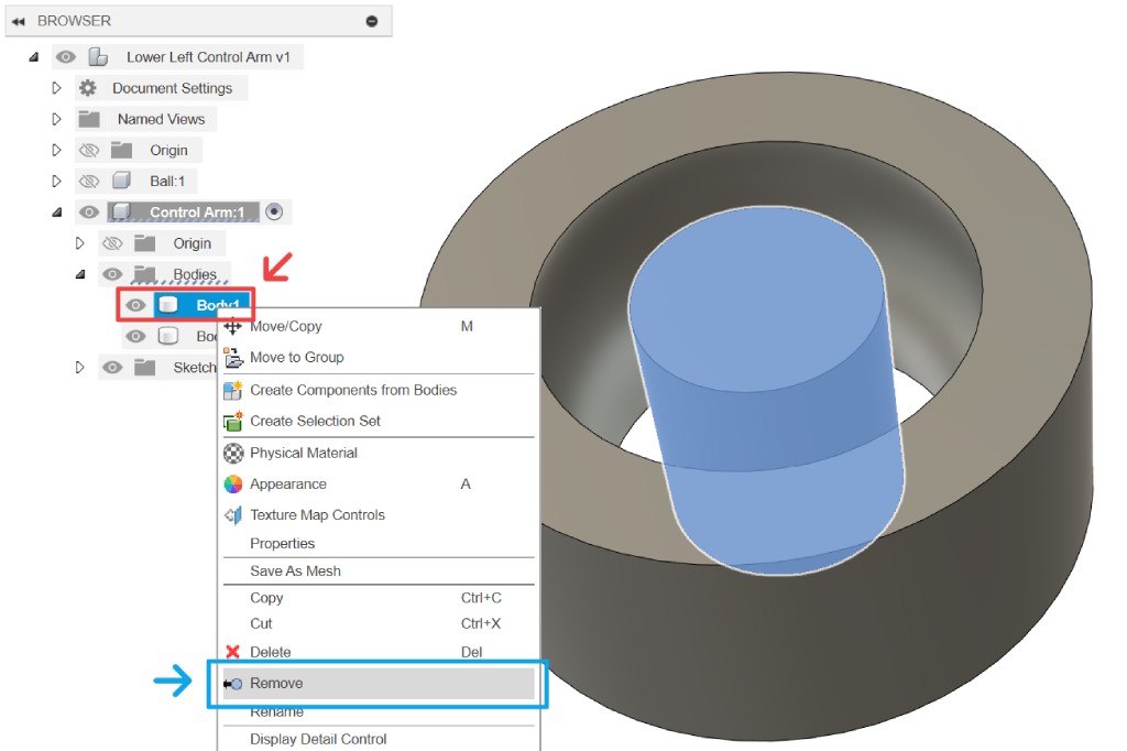
Enter ↩. - The boolean operation will leave a cylinder in the middle of the socket. Locate the body inside the browser, as shown in Figure 6. Right-click on the body, and then click remove.
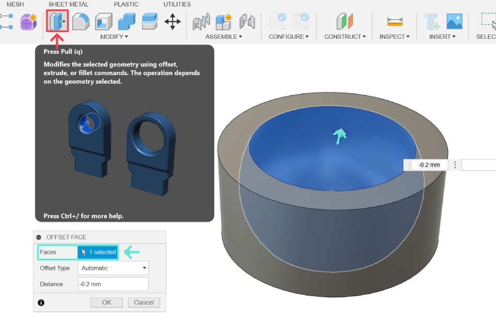
And the last step is to add spacing between the cavity surface and the ball geometry. Use the press pull tool, select the cavity face, and input -0.2 mm as the distance value, as shown in Figure 7.
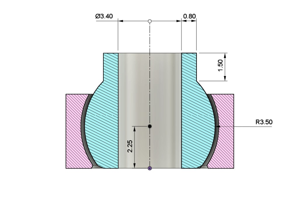
Now, if you cut both components in half, the cross-section would look like what is shown in Figure 8. As you can see, although this model is relatively simple, it is impossible to be made subtractively because the ball is enclosed within the socket cavity. This method is usually referred to as print-in-place. The only other way to create functioning ball joints is to fabricate multiple components that will be assembled or press-fitted together.
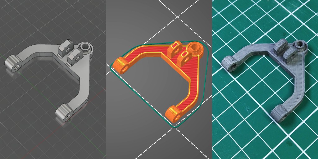
Modeling The Arms
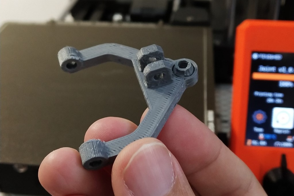
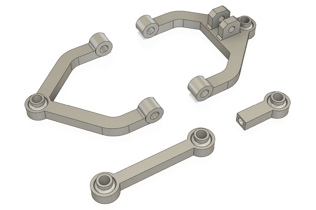
With the ball and socket components modeled, you can use them in a variety of applications by designing arms around the socket. The example below demonstrates their application in modeling a set of double wishbone suspension control arms, a connecting rod, and a generic ball joint that can be screwed onto a threaded rod.
3D Print
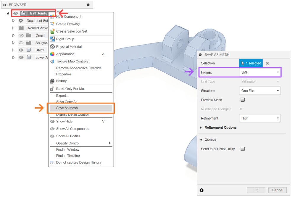
To 3D print your model, you need to export it as a mesh first. Right-click on the root of your browser panel and select the save as mesh option. Choose the specific format you want to export it in, then press the OK button or Enter ↩.
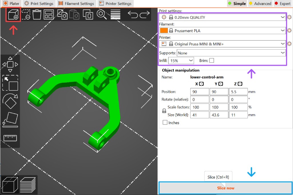
Open PrusaSlicer and add your mesh file using the tool located in the top left corner, as shown in Figure 9. Adjust your basic slicer settings such as layer height, infill, support, etc., in the right panel. For more advanced settings, you can access the expert tab. Once you are satisfied with the settings, proceed with slicing by clicking the slice now button in the lower right corner.
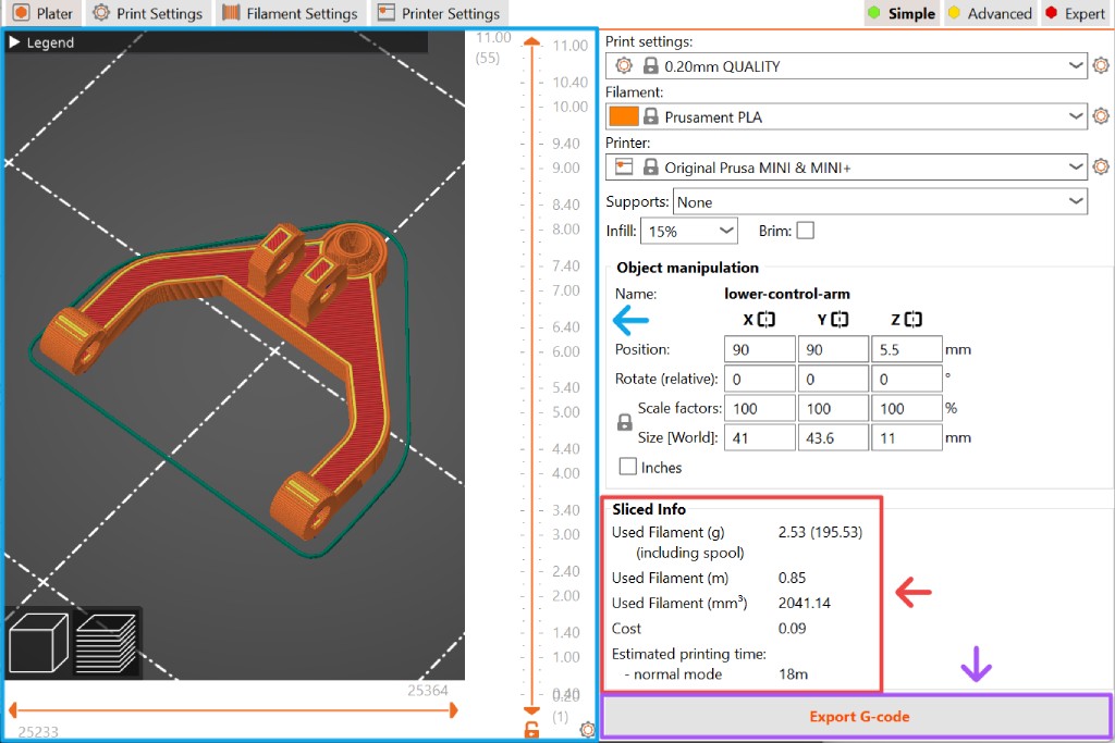
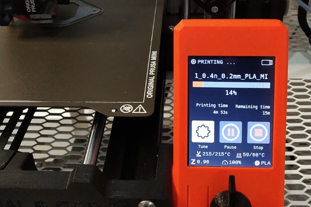
After the slicer has finished calculating, it will show you a preview viewport similar to Figure 10. You can observe the simulated printing in the viewport and review a summary of the printing process estimation on the right panel. If necessary, you can further tweak the settings and redo the slicing process. Once you are satisfied with the result, click the export G-code button in the lower right corner. Transfer the G-code file to a USB stick, plug it into the 3D printer, and start the print.
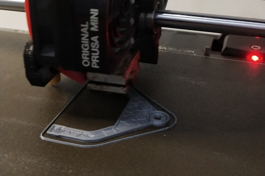
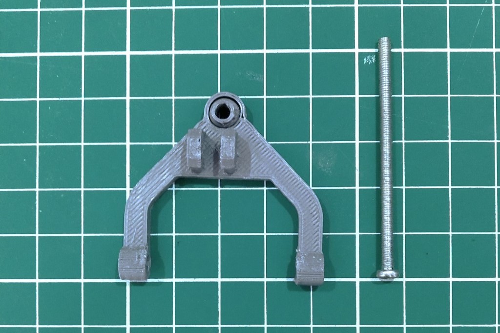
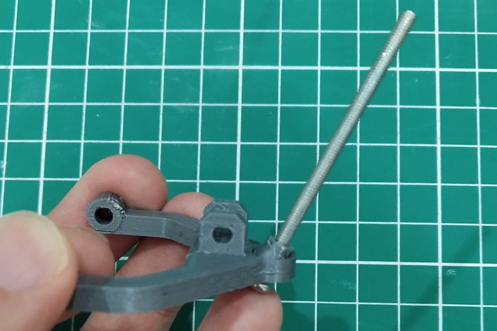
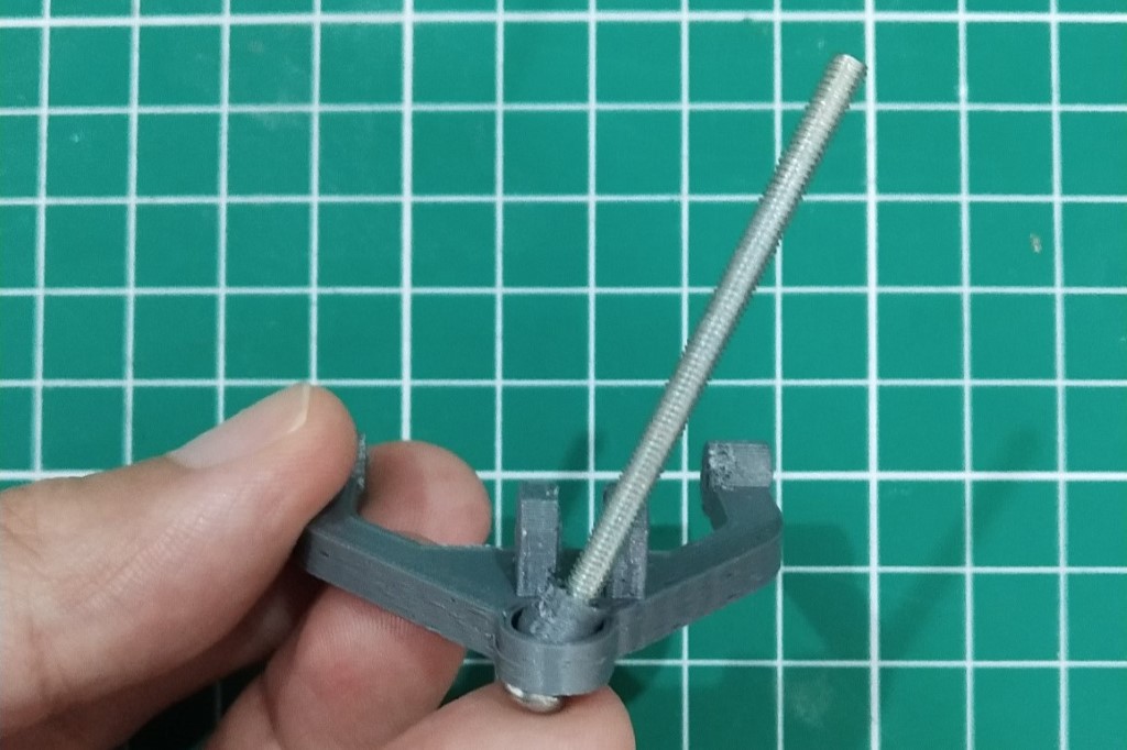
Once the print is finished, remove your model from the print bed and clean it up where necessary. Depending on your printer's tolerance, the ball joint might still be slightly stuck inside the socket. You can use a 3 mm bolt to help gently loosen up the joint.