3D Modeling Final Project Concept with Fusion 360
Modeling a Multi Components Object
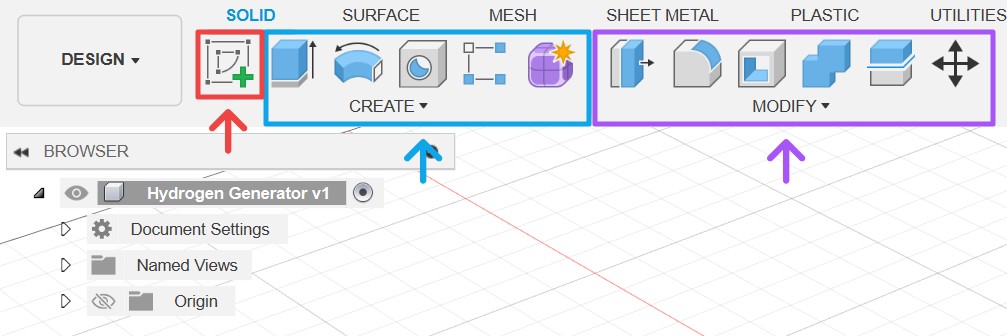
Fusion 360 divides its UI into multiple workspaces that you access through the top left dropdown menu. Each workspace is divided into multiple tabs, and each tab is further divided into groups based on functions. Each group shows an editable selection of commonly used tools and stores the rest inside a dropdown menu. Make sure you are in the design workspace with the solid tab.
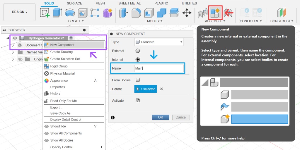
We are going to design an object that consists of multiple components. The first important step for it is to create new component first, give it a name, and click ok or press Enter ↩. By doing this first, your project will be nicely organized. Sketches can be stored in their own component, and you can isolate your design history to each specific component among other benefits. You can also do it by right-clicking a component on the browser and choose new component.
Model Blocking
When you draw something, you usually do a rough sketch of the overall drawing first before refining and adding details later. It is a good practice too to do the same thing when you do 3D modeling. You create a simplified version of your model to establish shape, size, and layouts to quickly iterate on the design and proportions. This process is called blocking.
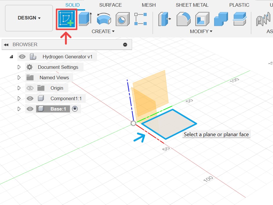
Let's start by creating the base. Click create sketch, select the XY plane, then you'll enter the sketch contextual tab just like shown in figure 2. Next, we use 2-point rectangle (shortcut r), start drawing it from the origin point to the top right. Then, we give dimensions (shortcut d) to the X 275 mm and the Y 300 mm.
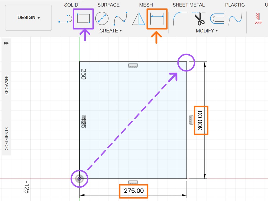
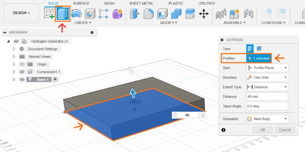
Click finish sketch, then you will exit the sketch tab. Click extrude tool (shortcut e), select the profile from your sketch, and extrude it by 40 mm. You are done with the base for now. Create a new component and name it enclosure.
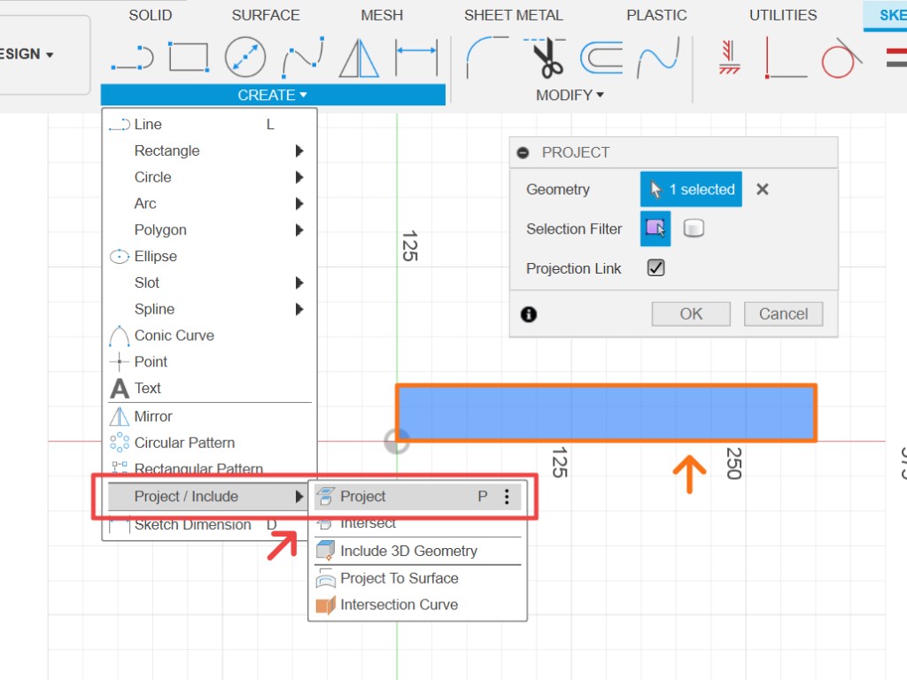
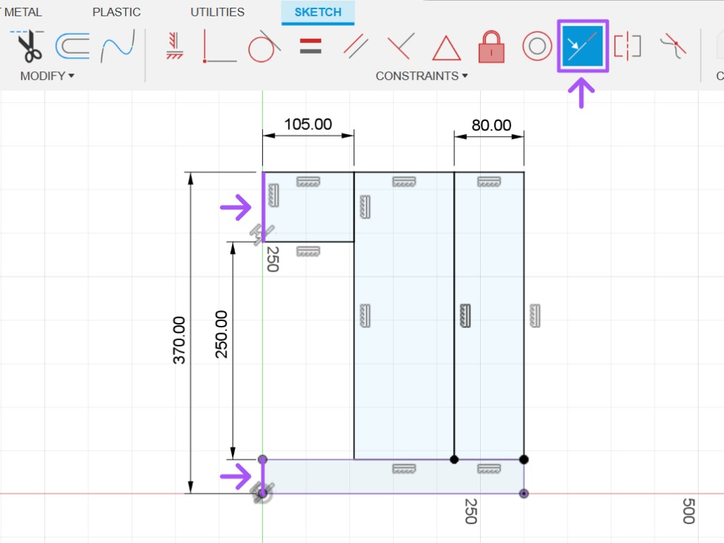
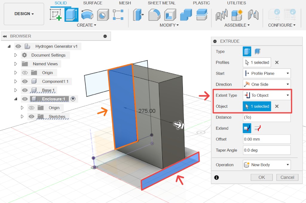
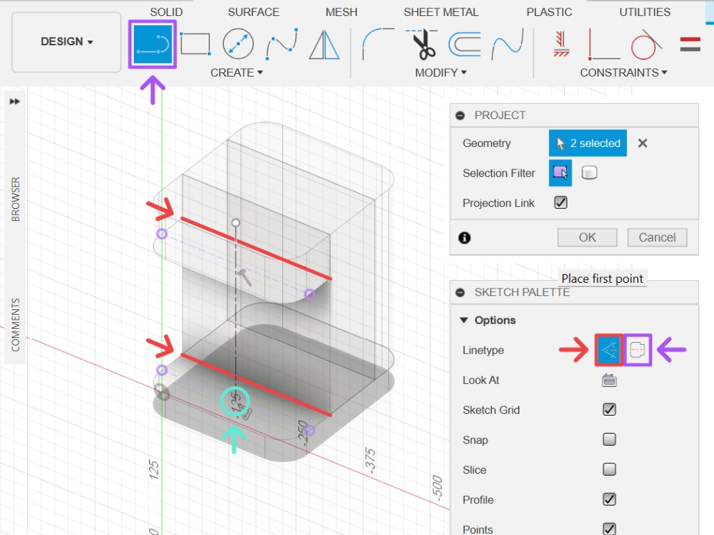
In the new component, create sketch on the YZ plane. We want to reference the base, and we can use the project tool (shortcut p) to select the base as shown in figure 3. Create three new rectangles and provide dimensions as depicted in figure 4. Apply a collinear constraint between the two leftmost edges.
Finish the sketch and extrude the middle rectangle. Instead of inputting a number as the distance value, we can change the extent type to "to object" and select the base's right side as the reference. Now, our enclosure will always have the same width as the base. This is a form of parametric modeling; if we ever change the width of the base, the enclosure will follow suit.
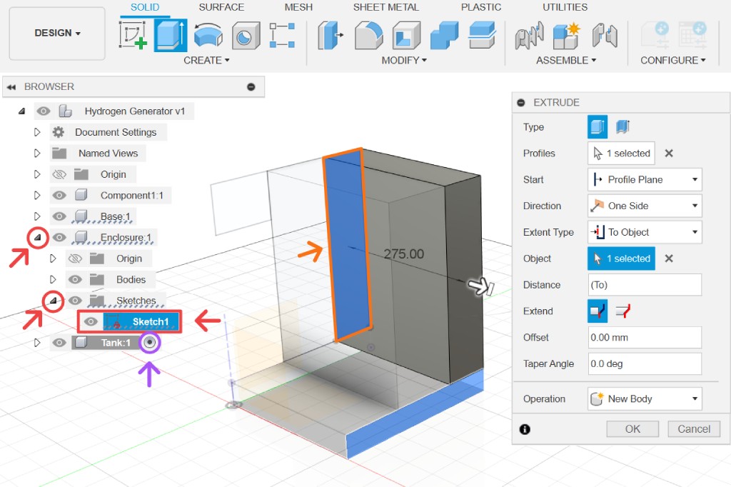
Create another component and name it tank. After you perform an operation using a sketch like we did in the previous step, Fusion automatically hides the sketch. However, in certain cases like this one, you might want to use it for another component. You can toggle its visibility by going to the browser tree and clicking the eye icon, as shown in figure 5.
Make sure your active component is the newly created component. When you set a component as the active component, the other components will be shown semi-transparently. Select the extrude tool, choose the right rectangle, then repeat the previous step.
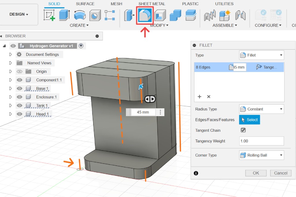
Repeat the same step for the last rectangle. Select the fillet tool (shortcut f) and choose all the edges, as shown in figure 6. Drag the blue arrow or input 45 mm as the fillet value. Now you have finished blocking out the body of our device.
Modeling Canister
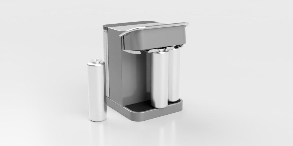
The concept of this device involves using the electrolysis process, which splits water into hydrogen (H2) and oxygen (O2) gases. These gases will be stored in canisters, so let's create a new component and name it canister.
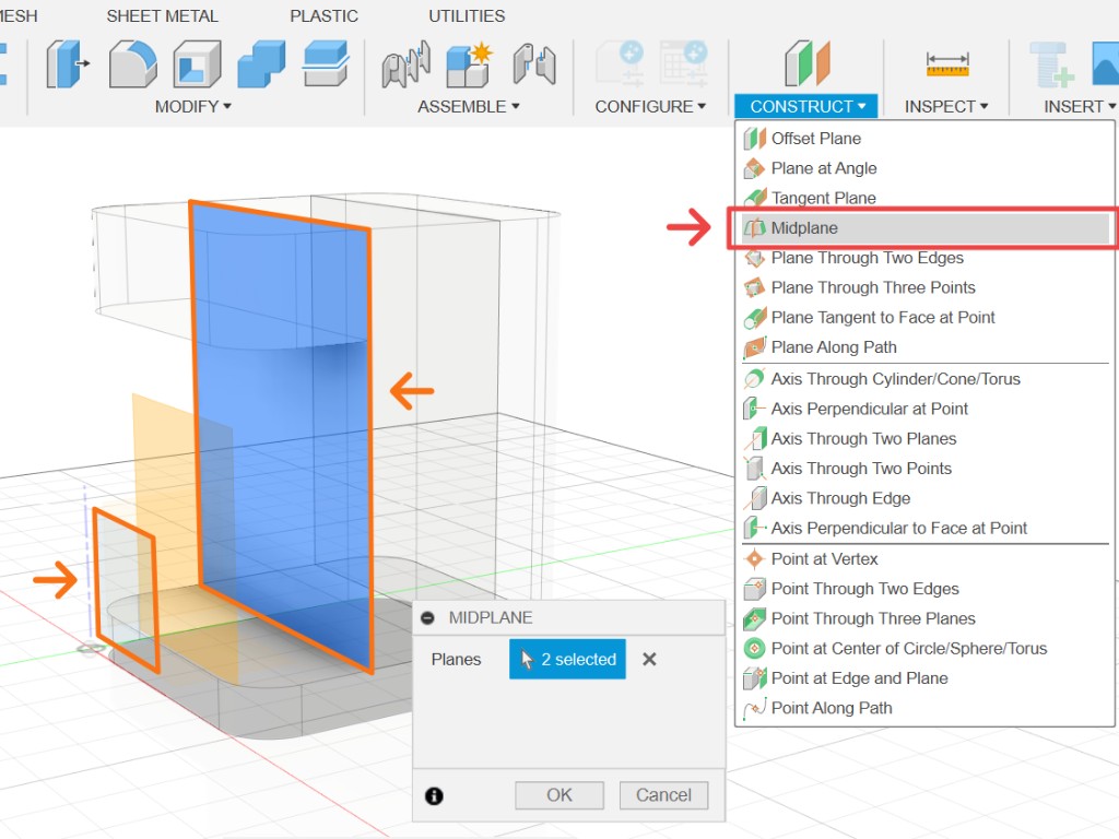
So far, we have been using planes on the origin, but there are times, such as this, where it will be more convenient to have a different plane. Use the midplane tool and select the enclosure front face and XZ plane. This will create a new plane right in the middle between the selected planes, as shown in figure 7. It's another parametric operation; if the dimensions of the enclosure change, the plane will always adjust to the middle.
Create a sketch on that plane. Choose the construction linetype, then create projections as shown in figure 8. To make it easier to select the component to project, you could rotate your viewport in sketch mode. Next, use the line tool (shortcut l) and select centerline as the linetype. Hover around the center of the bottom projected line. When it shows a triangle, it indicates that the vertex will be placed right in the middle of that line. Next, place the second vertex in the middle of the other projected line.
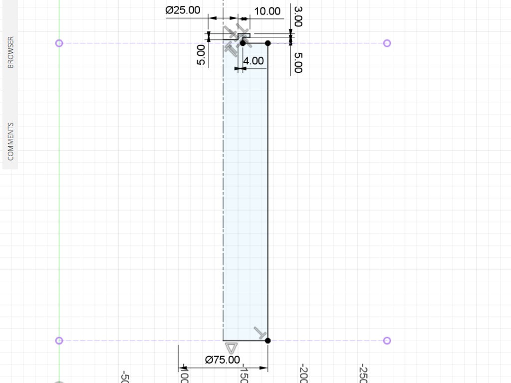
Still in the same sketch, use the line tool to create half of the profile of the canister. See figure 9 as a reference and add all the dimensions accordingly. When setting dimensions from a centerline, it will set the overall length instead of the dimension from the line itself. This makes things easier, as in this example, because we can set the dimension of the canister to its diameter (75 mm) instead of having to specify it as the radius.
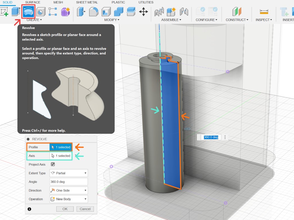
Finish your sketch and select the revolve tool. In this tool, you need to select the profile we just sketched and the centerline as its axis. Once done, add fillets to the body of the canister to round it up.
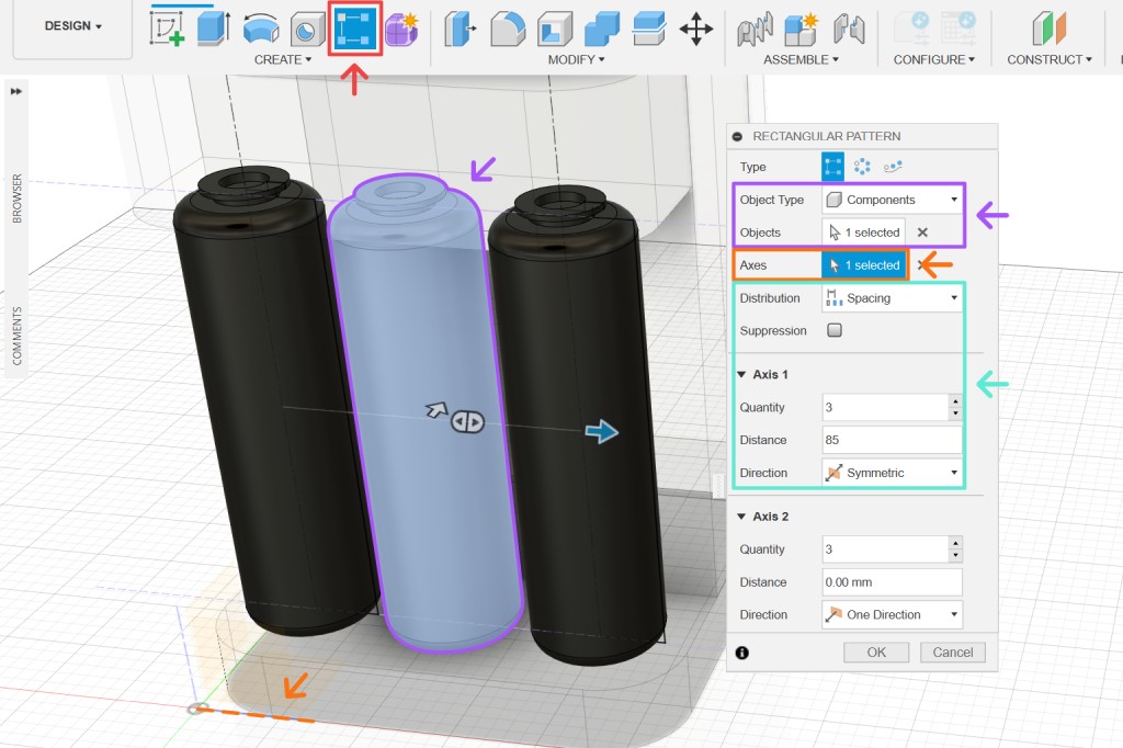
Electrolysis of water will produce twice the amount of hydrogen compared to oxygen; therefore, we will need three canisters. We can copy and paste the canister, but it's better to use rectangular pattern for this because it offers more parametric control. Follow the steps below to create two copies of the canister to its left and right.
- Choose type as components and select the canister component.
- Select X as the axis.
- Select distribution as spacing, direction as symmetric, set quantity to 3, and distance to 85 mm.
Detailing
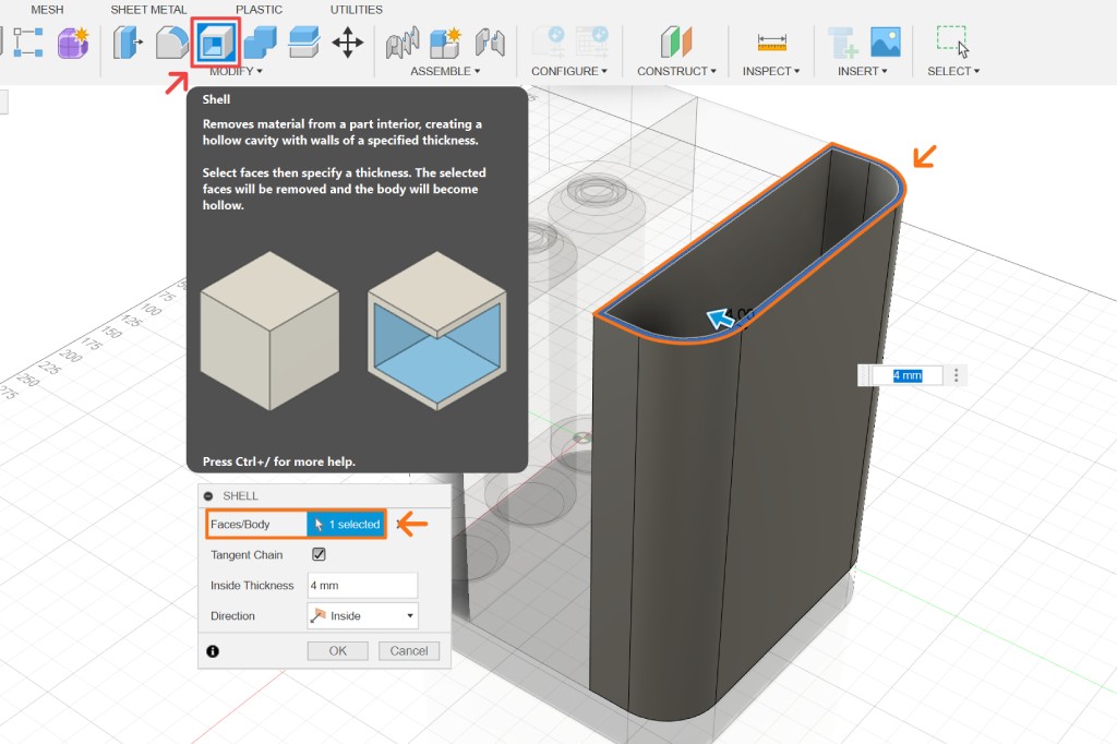
The detailing process is not any different from what we have done so far. For example, let's add details to the tank, which is currently still a simple solid box with some rounded edges. To carve the cavity, we can use the shell tool. Select the top face as the opening and specify a thickness of 4 mm for the shell.
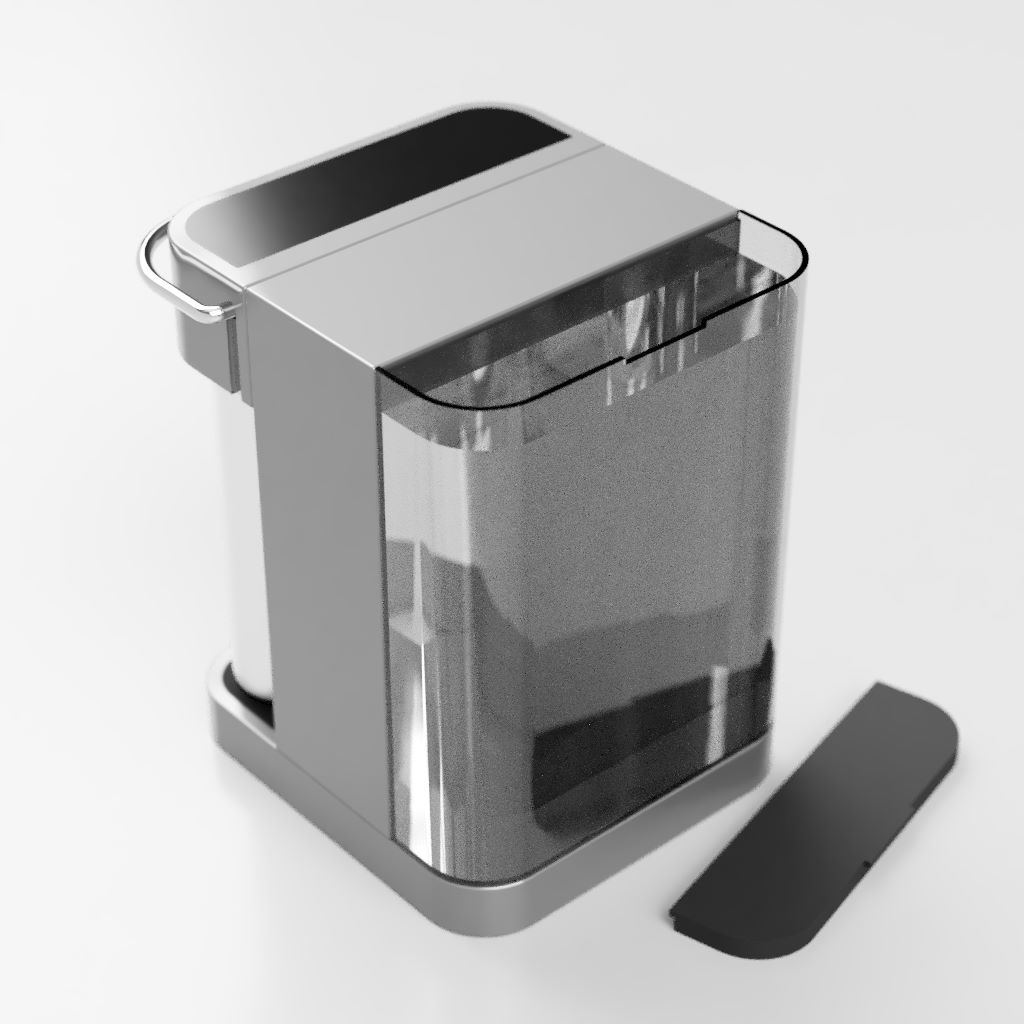
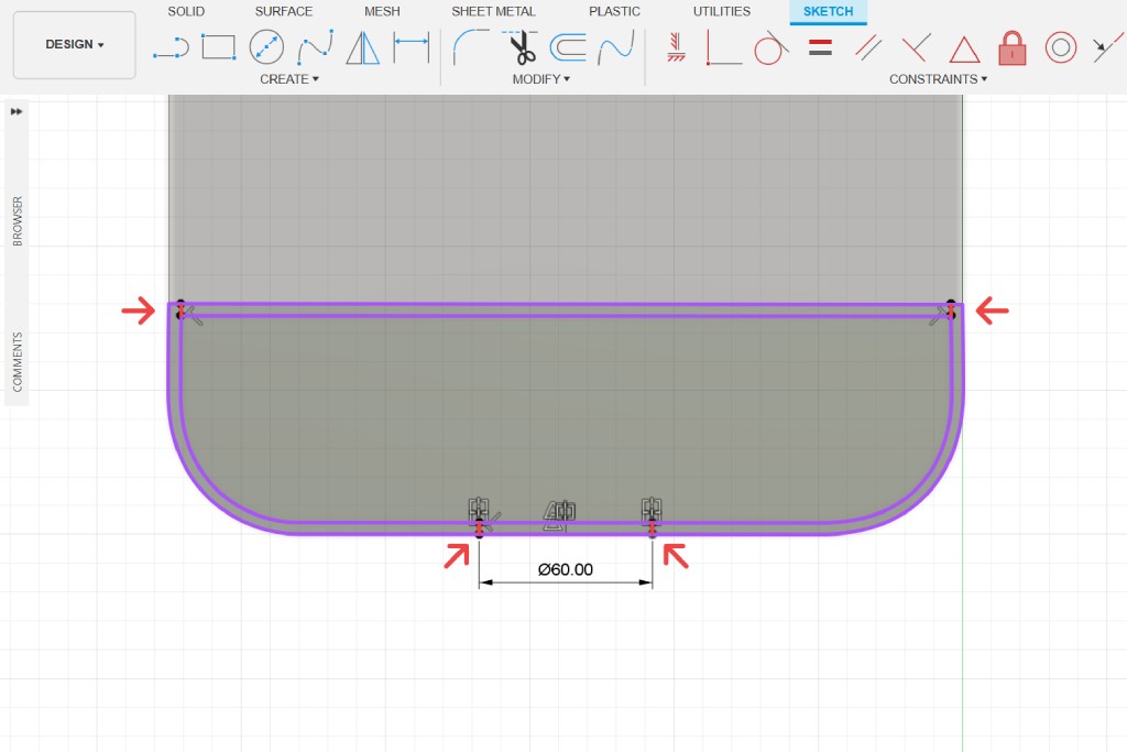
We will need some indentation on the body where a lid can sit on top of the tank opening. Besides a plane, we could also select a face when we start a sketch. Create a sketch by selecting the tank lid face. See figure 11 as a reference to add lines with specified dimensions.
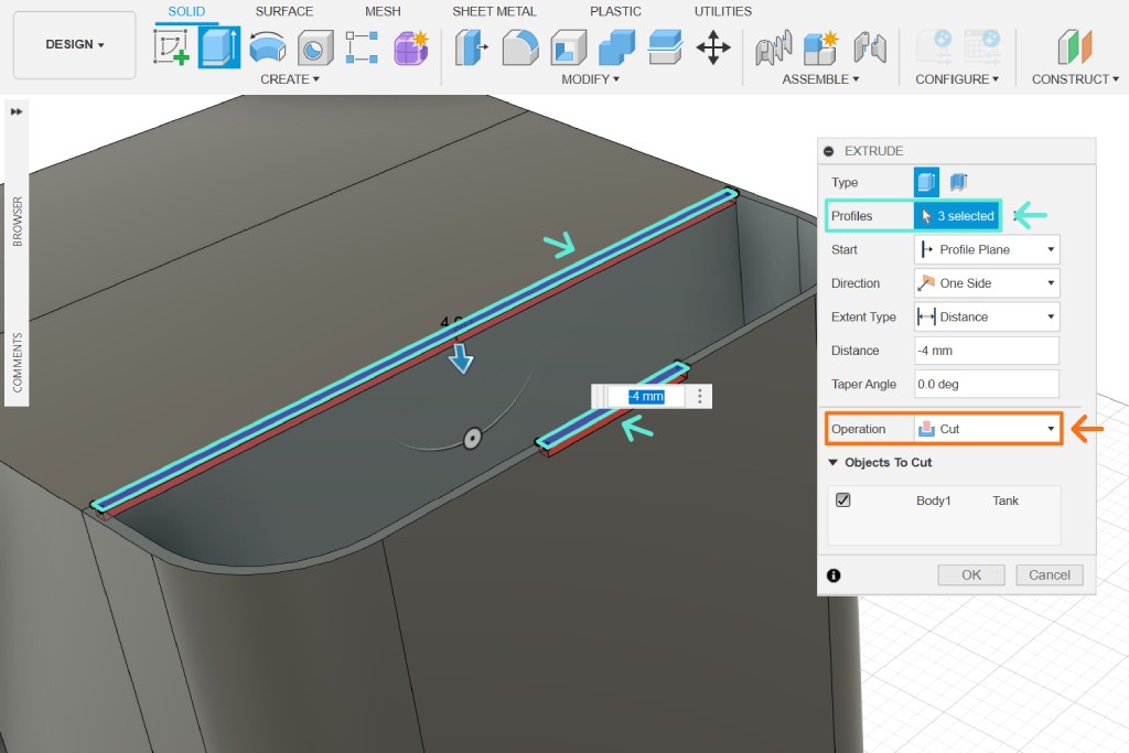
Finish the sketch, select the extrude tool, then choose the profiles as shown in figure 12. Extrude downwards by -4 mm and make sure the operation changes to cut.
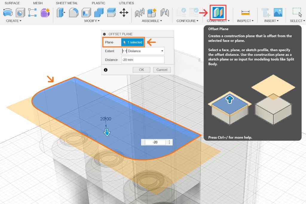
Let's create a handle for the head component next. Another common tool to add a plane is by using offset plane. Select the top face of the head component as the plane, and drag down the blue arrow or input -20 mm as the distance value.
See figure 13 as a reference. Create a sketch on the newly created plane and project a construction of the head component. Follow the steps below to create the path for our handle:
- Use the offset tool (shortcut
o) to select the highlighted path and offset it by 15 mm. - Create two lines perpendicular to each other on one end of the offset line and give a 15 mm offset from the top as shown.
- Fillet the corner and specify a 8 mm radius.
- Create a centerline in the middle of the sketch.
- Mirror the lines to the other side.
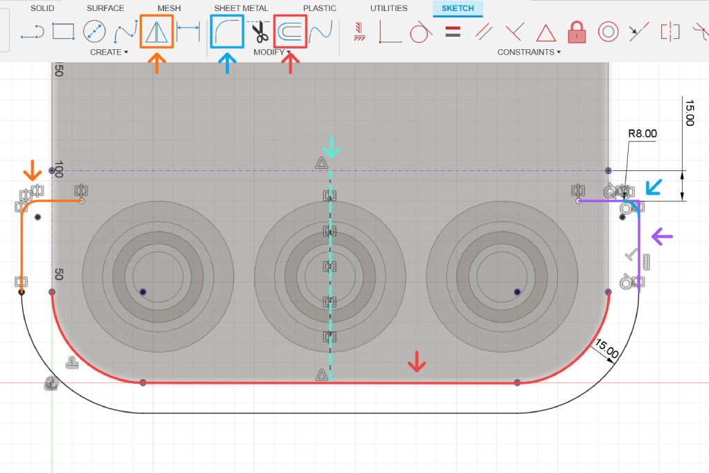
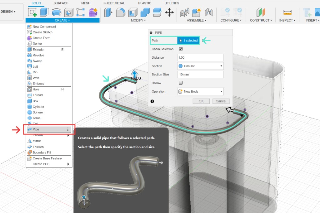
Finish the sketch, then use the pipe tool, and select the path we just created. Set the section size to 10 mm, and the component is finished.
Modeling Workflow Overview
There are many ways to model an object, but 80% of the time, the workflow will be rather rhythmic. First, you sketch something on a 2D plane, then you create a body from that sketch, i.e., extrude, revolve, etc.; then you modify that body, i.e., fillet, chamfer, draft, etc. Then you repeat the process again and again until you achieve your desired shape. You'll notice that the design toolbar was designed to mimic that flow too: sketch → create → modify.
Keep adding new components or adding more details to existing ones by following this workflow. For creating a concept render, we just need enough details to make it look like a believable or working product.
Design History

The bottom of your screen will look similar to the images above. This is Fusion's design history feature, where it records all the commands that you perform in the file. You can double click on any of the icons to edit the command, and it will update your file accordingly. You can drag the marker back and forth to go back in time, suppress some features, reorder them, or even delete them altogether. This feature is very helpful for learning by examining the history of someone else's design. You can watch the playback of your file, just like shown in the video below.
Animation
If your product has moving components, you can demonstrate it in Fusion's animation workspace. Using the transform components tool (shortcut m), you can select which component you want to animate. Then, you can move or rotate it using the gizmo. The transform will be recorded in the timeline, where you can adjust the timing and duration of the animation by moving and scaling the time block respectively.
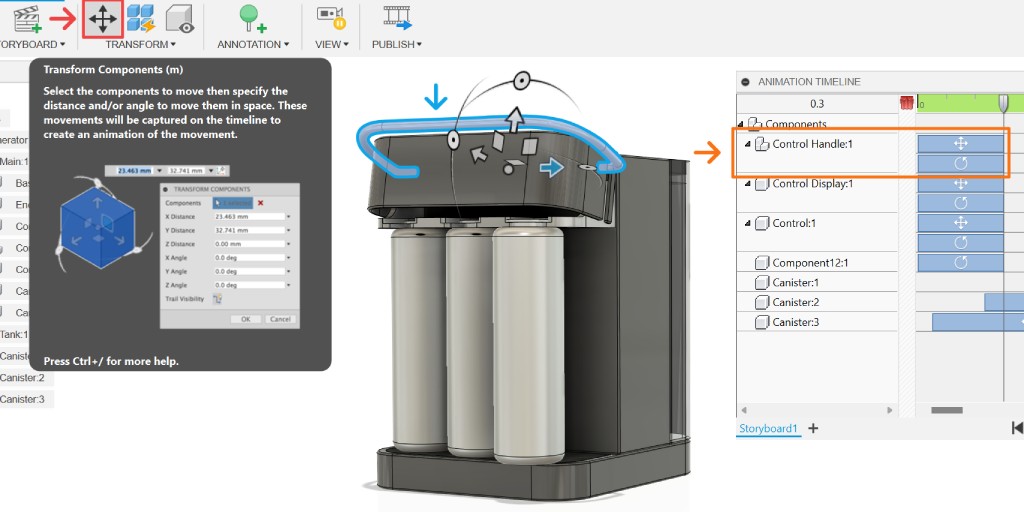
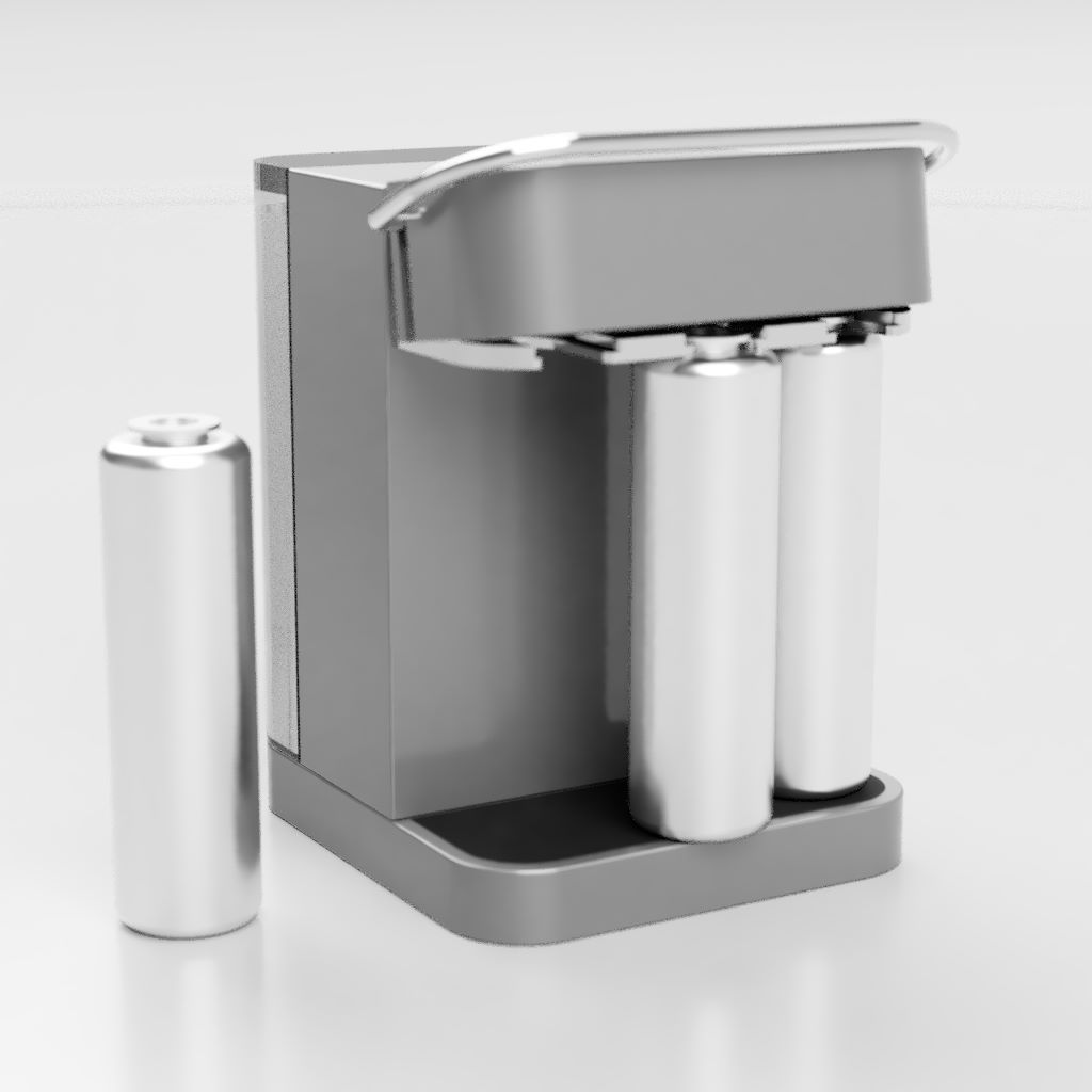
Below is an animation that demonstrates the process for unmounting the canisters from the device. You can create more animations independently from each other by creating new storyboards.
Render
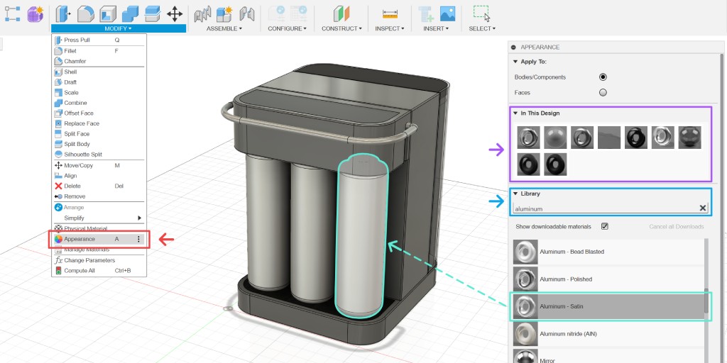
By default, Fusion applies steel with satin material to all components. To apply different materials, you need to access the appearance tool (shortcut a). You can see all the currently used materials inside your design and search for available materials from the library. To apply a material, click and drag the thumbnail to the component you want to apply it to. You can do it both from the library thumbnail or from the currently used materials thumbnail.
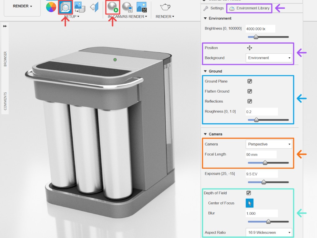
To generate an image or video rendering, you need to go to the render workspace. Access the render setting from the toolbar, and you can also activate the in-canvas renderer to get real-time feedback if your computer specs are strong enough to handle it. Fusion doesn't have robust camera and render settings like software such as Blender, but it has enough to create simple product renderings such as:
- Environment of the rendering, which will affect the overall lighting of the scene. You can adjust its brightness, position, rotation, and the option to actually render the environment as the background or set it to another color.
- Include a ground plane, set a reflection, and how reflective it is.
- Camera focal length.
- Depth of field and aspect ratio.
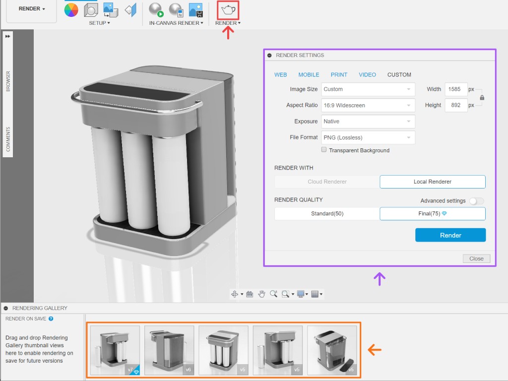
Once you are happy with the render settings, you can click the render button. In the pop-up panel, you can specify the format and dimensions, then click render. Once you do that, it will queue the render in the rendering gallery. When it's done, you can click the thumbnail and download your rendered image.
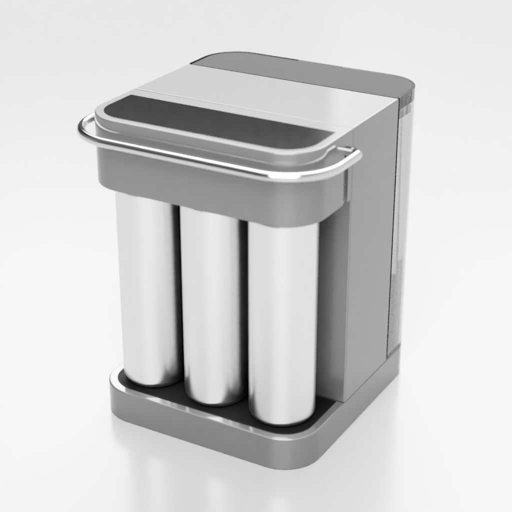
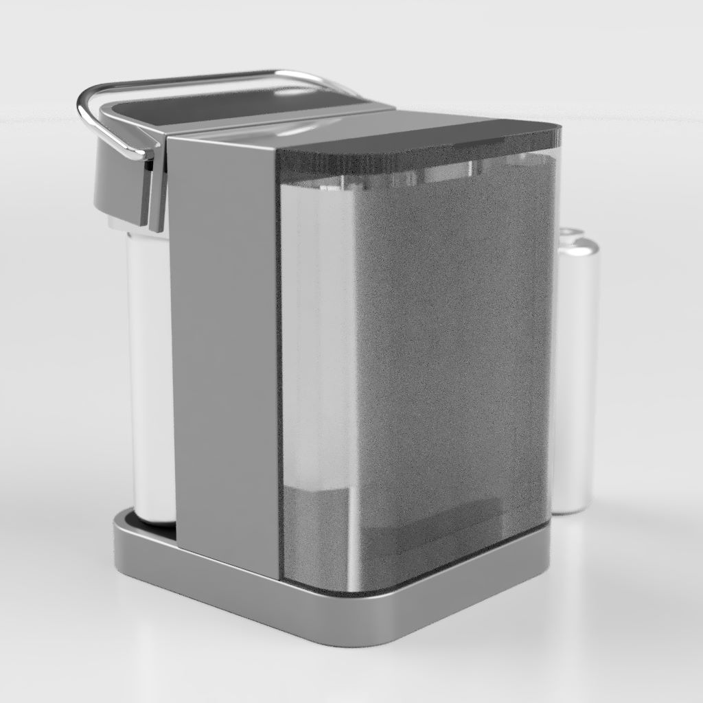
Below are the image renderings from this project. For better demonstration, it is useful to render your project from multiple angles and depict some scenarios of use. For example, the example below shows how the head part opens up when we want to mount or unmount the canisters. It also shows the tank lid opened and how much water the tank could hold.