I2C Communication Protocol
I2C or sometimes also referred as IIC stands for Inter-Integrated Circuit. It is a type of synchronous serial communication protocol using 2 wires, SDA (serial data) to transmit the data bit by bit between master and slave and SCL (serial clock) for sending clock signal for the data synchronization.
Compared to UART (universal asynchronous receiver-transmitter), I2C allows for multiple peripherals (slaves) to communicate with one or multiple controller (masters). SPI (serial peripheral interface) can do the same with higher data speed transmission, but at the cost oh requiring additional wire for each additional peripheral. There are other serial communication protocols, but these 3 are the most common. Watch this excellent explanation video by Electronoobs to learn the comparison and differences between them in depth.
Hardware Setup
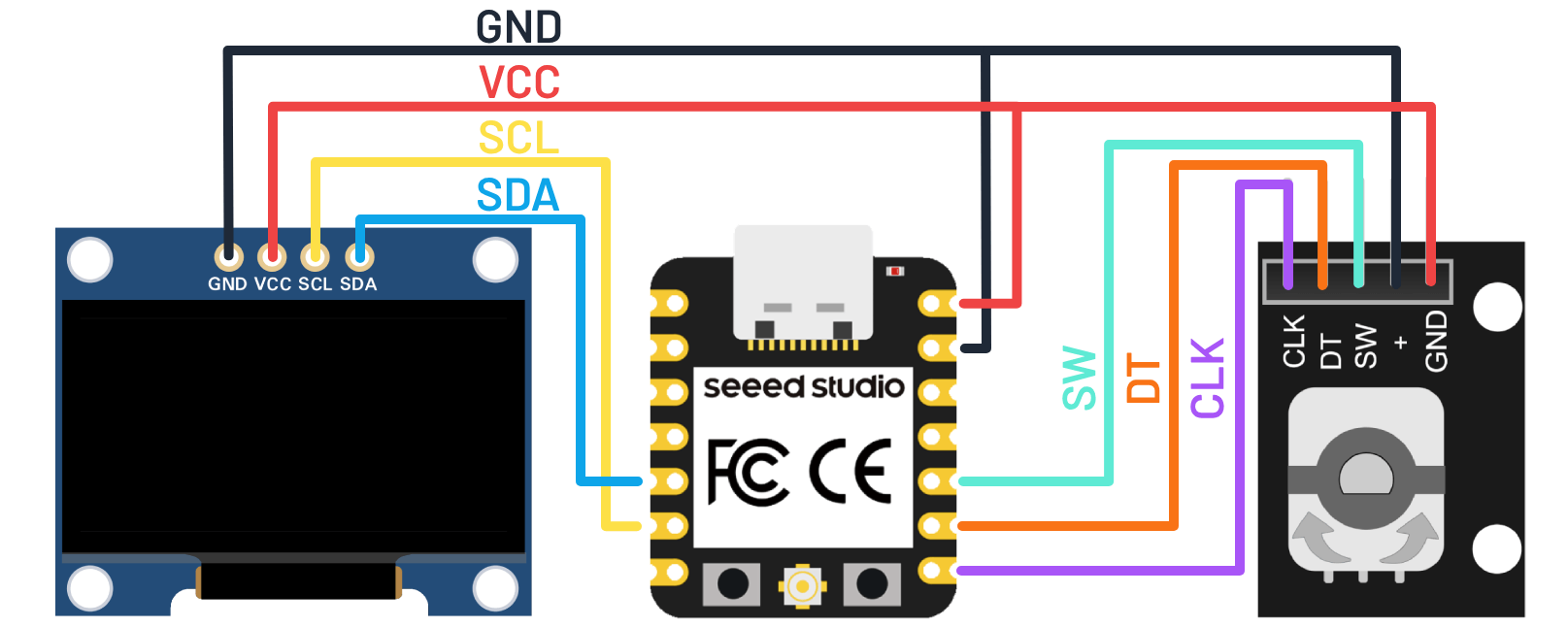
We have seen how to wire I2C communication from the output device assignment where we work with a 0.96" OLED display. In short, we connect GND and VCC to power, SDA and SCL to corresponding pin on our controller. You can learn more how to connect multiple chips together using I2C communication by watching this YouTube video by Foolish Engineer.
In this article we also going to use rotary encoder as our input device just like shown in the input device assignment. We need to connect GND and VCC to power, the rest of the pins - CLK, DT, and SW - can be connected to any digital pin.
Hexadecimal Address
Like discussed on the OLED display article, each I2C peripheral has a hexadecimal address that the controller can use to communicate with. According to Adafruit SSD1306 example sketch, 0.96" OLED display with 124 x 64 resolution address is 0x3D. However, this is not always guaranteed, it could vary from one manufacturer to another. The module that we use has address set to 0x3C by default.
If you could not figure out the address of your peripheral, you can upload an I2C scanner program like shown below. This program is based from an instructable tutorial by Mission Critical. It's a simple program that initiate wire transmissions and print out any addresses that detected to receive a transmission.
#include <Wire.h>

void setup() {
  Serial.begin(115200);
  Serial.println("I2C scanner. Scanning ...");

  byte count = 0;
  Wire.begin();

  for (byte i = 1; i < 120; i++) {
    Wire.beginTransmission (i);

    if (Wire.endTransmission () == 0) {
      Serial.print("Found address: ");
      Serial.print(i, DEC);
      Serial.print(" (0x");
      Serial.print(i, HEX);
      Serial.println(")");
      count++;
      delay(1);
    }
  }

  Serial.print("Found ");
  Serial.print(count, DEC);
  Serial.println(" device(s).");
}

void loop() {}
Communication Frames
I2C protocol has a very specific sequence of data transmission. Library like Adafruit SSD1306 makes it really simple to use the display without the need to really understand how the controller transmits the data. You can watch this YouTube explanation video by the same Foolish Engineer channel to learn more in depth how I2C data transmission is structured. Here is a short summary of I2C communication frames:
- Start Bit: SDA goes low before SCL transitions to indicate the beginning of an I2C communication from a controller (master).
- Address Frame: Then the controller send the peripheral's (slave) unique binary address to indicate which peripheral it wants to communicate with.
- Read/Write Bit: The controller specifies whether it wants to send or request data.
- ACK/NACK Bit: The addressed peripheral will send acknowledge to the controller indicating the data or bit has been received. If the peripheral got disconnected for whatever reason, the controller will detect it as no-acknowledge and could be programmed to handle such occurrence. This ACK or NACK bit will be sent after every data frame.
- Internal Register Frame: Specifies which internal register of the peripheral will be read from or write to by the controller.
- Data Frames: Where the actual data will be send or received.
- Stop Bit: Once all the data has been transmitted, the SDA goes high after SCL transitions to indicate the end of communication.
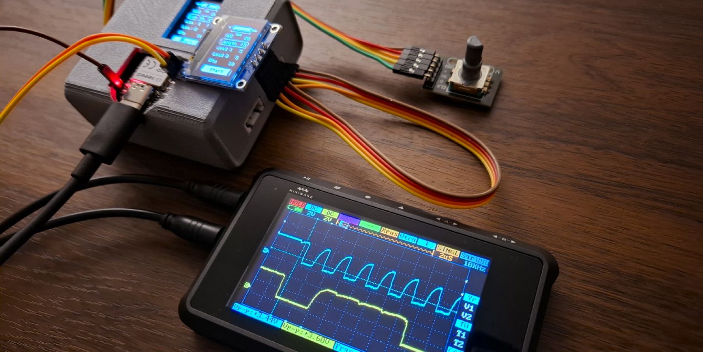
In the video below, you can see the I2C communication in action seen from an oscilloscope. Channel A is connected to SCL pin and channel B is connected to SDA pin.
Practical Example
This example is a culmination of multiple assignments, starting from electronic design, output device, and input device. The most notable update is the serial monitor program has been abstracted into it's own class library named Oled_Console by extending Adafruit_SSD1306. Now we can simply include the library to use an OLED display as a mini serial monitor.
/* Oled_Console.h */
#ifndef OLED_CONSOLE_H
#define OLED_CONSOLE_H
#include <Arduino.h>
#include <Wire.h>
#include <Adafruit_GFX.h>
#include <Adafruit_SSD1306.h>

class Oled_Console : public Adafruit_SSD1306 {
  public:
    Oled_Console(uint8_t w, uint8_t h, int8_t rst_pin = -1);
    void begin(unsigned long baud, uint8_t i2caddr);
    void print(String txt);
  private:
    void push(String txt);
    void update();
};

#endif

// -----------------------------------------------------------------------------------------------

/* Oled_Console.cpp */
#include "Oled_Console.h"

Oled_Console::Oled_Console(uint8_t w, uint8_t h, int8_t rst_pin)
  : Adafruit_SSD1306(w, h, &Wire, rst_pin) {}

void Oled_Console::begin(unsigned long baud, uint8_t i2caddr) {
  Serial.begin(baud);

  if (!Adafruit_SSD1306::begin(SSD1306_SWITCHCAPVCC, i2caddr)) {
    Serial.println(F("SSD1306 allocation failed"));
    for(;;); // Don't proceed, loop forever
  }

  Adafruit_SSD1306::setTextColor(SSD1306_WHITE);
}

void Oled_Console::print(String txt) {
  Oled_Console::push(txt);
  Oled_Console::update();
  Serial.println(txt);
}

const byte console_buffer_size = 8;
String console_buffer[console_buffer_size] = {};

void Oled_Console::push(String txt) {
  for (int i = console_buffer_size - 1; i > 0; i--)
    console_buffer[i] = console_buffer[i - 1];

  console_buffer[0] = txt;
}

void Oled_Console::update() {
  Adafruit_SSD1306::clearDisplay();
  Adafruit_SSD1306::setCursor(0, 0);

  for (int i = 0; i < console_buffer_size; i++)
    Adafruit_SSD1306::println(console_buffer[i]);

  Adafruit_SSD1306::display();
}
Another small update added is a new library named Debounce_Trigger. A button or any kind of switch is used widely in many projects but as we have seen, it requires quite a bit of code to make it works reliably. This might not be cumbersome if you only have one or two, but it quickly become one as the project grows. This library abstracted a very common button or switch programming pattern with a combination of Debounce library from machine design assignment which utilize millis underneath it for it's timing function.
/* Debounce_Trigger.h */
#ifndef DEBOUNCE_TRIGGER_H
#define DEBOUNCE_TRIGGER_H
#include <Debounce.h>

class Debounce_Trigger {
  public:
    Debounce_Trigger(byte pin, unsigned long time = 50);
    void debounce(std::function<void()> trigger_callback, std::function<void()> release_callback = {});
  private:
    Debounce deb;
    byte _pin;
    unsigned long _time;
    bool triggered = false;
};

#endif

// -----------------------------------------------------------------------------------------------

/* Debounce_Trigger.cpp */
#include "Debounce_Trigger.h"

Debounce_Trigger::Debounce_Trigger(byte pin, unsigned long time) {
  _pin = pin;
  _time = time;
  pinMode(pin, INPUT_PULLUP);
}

void Debounce_Trigger::debounce(std::function<void()> trigger_callback, std::function<void()> release_callback) {
  deb.debounce([this, &trigger_callback, &release_callback]() {
    if (digitalRead(_pin) == LOW && !triggered) {
      if (trigger_callback)
        trigger_callback();

      triggered = true;
    } else if (digitalRead(_pin) == HIGH && triggered) {
      if (release_callback)
        release_callback();

      triggered = false;
    }
  }, _time);
}
Below is the main sketch shown on the input device assignment. With those programs abstracted to multiple libraries, the implementation become really clean, easy to understand, and easily reusable.
/* Rotary_Demo.ino */
#include <Debounce_Trigger.h>
#include <Oled_Console.h>
#include <Rotary_Encoder.h>

#define SW D9
#define DT D8
#define CLK D7

Debounce_Trigger btn(SW);
Rotary_Encoder rotary(DT, CLK);

#define SCREEN_I2C_ADDR 0x3C // or 0x3D
#define SCREEN_WIDTH 128     // OLED display width, in pixels
#define SCREEN_HEIGHT 64     // OLED display height, in pixels

Oled_Console console(SCREEN_WIDTH, SCREEN_HEIGHT);

void setup(){
  console.begin(115200, SCREEN_I2C_ADDR);
  console.setRotation(2);
  console.print("Rotary Encoder Demo");
}

void loop(){
  btn.debounce(&click);
  rotary.decode(&countUp, &countDown);
}

int counter = 0;

void countUp() {
  counter++;
  console.print("Count up: " + String(counter));
}

void countDown() {
  counter--;
  console.print("Count down: " + String(counter));
}

void click() {
  counter = 0;
  console.print("Reset counter");
}