Working with a Rotary Encoder

The Basic
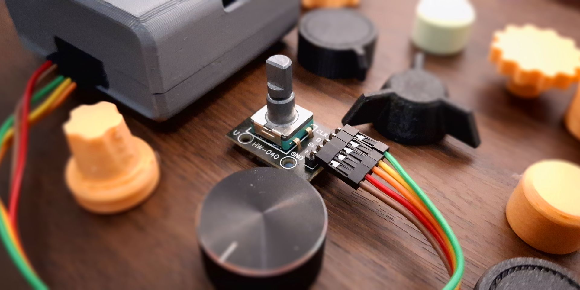
Rotary encoder is a very common component used in many machines such as 3D printer as their primary or only input peripheral. It's primary function is to indicate how much and which direction the knob has been rotated and commonly comes with a button built into it. With the combination of rotation and clicks, it can be used for navigating simple user interface, traversing nested menu, increasing or decreasing values, changing options, and many more. This makes it a robust, intuitive, yet economical input peripheral.
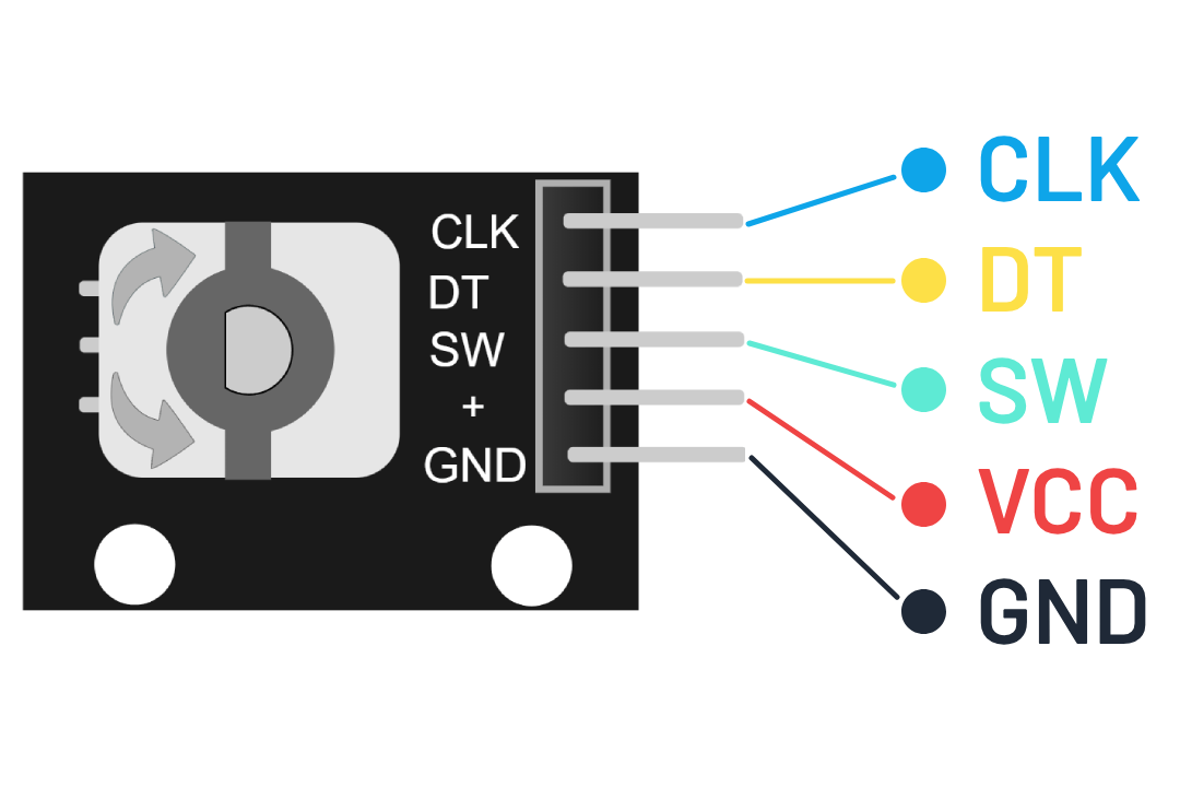
There are different types of rotary encoder, but all of them works with the same principle. In this article, we will be using a very common rotary encoder module, HW-040. It has 5 pins - GND, VCC (5 V), SW, DT, and CLK. The GND and VCC should be connected to power, the rest can be connected to any digital inputs.
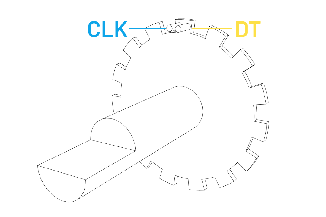
The main component consist of a shaft that rotates and clicks in small increments, with a total of 30 click positions in a full rotation. At the end of the shaft inside the component, there are series of conductive pads. As it rotates, those pads will connect and disconnect to two stationary pins that connected to CLK and DT pins, generating signal pulses that can be used to determine the rotation direction.


You can inspect the signal pulses on an oscilloscope like shown below to see the sequence of the signals. The blue line is connected to CLK pin and the yellow line is connected to DT pin. When you turn the knob clockwise, the CLK pin will changes state first, and then the DT pin change state after. Rotating the knob counter clockwise will reverse the order.
We can simply determine the direction by comparing the signal value sequence in our code just like shown in this Wokwi basic example below.
#define ENCODER_CLK 2
#define ENCODER_DT  3

void setup() {
  Serial.begin(115200);
  pinMode(ENCODER_CLK, INPUT);
  pinMode(ENCODER_DT, INPUT);
}

int lastClk = HIGH;

void loop() {
  int newClk = digitalRead(ENCODER_CLK);
  if (newClk != lastClk) {
    // There was a change on the CLK pin
    lastClk = newClk;
    int dtValue = digitalRead(ENCODER_DT);
    if (newClk == LOW && dtValue == HIGH) {
      Serial.println("Clockwise");
    }
    if (newClk == LOW && dtValue == LOW) {
      Serial.println("Counterclockwise");
    }
  }
}
Issue
The code above works perfectly fine in the simulation, unfortunately the exact same code might not work well on an actual micro-controller. The code runs very unreliably, it skip some steps when rotated fast, and occasionally read the wrong direction. The problem isn't exactly at the code itself, but instead the fact that the mechanical part of electronic component such as rotary encoder or button usually suffer from contact bouncing. When we rotate the knob, the contacts inside may momentarily lose and regain contact repeatedly, unintentionally generating multiple pulses.
Solution
From scouring multiple forums and many stack overflow threads, I find out that this is a very common issue people ran into. Many of them suggest to use a library by Buxtronix. It is a simple yet elegant and reliable rotary decoder using a simple state machine.
Below are the streamlined and refactored codes that packaged into a library. It use half step by default, eliminating the necessity to have two state tables. It also add decode method that accepts two callback methods, one for clockwise rotation and another for counter clockwise rotation.
/* Rotary_Encoder.h */
#ifndef ROTARY_ENCODER_H
#define ROTARY_ENCODER_H
#include <Arduino.h>
#include <functional>

class Rotary_Encoder {
  public:
    Rotary_Encoder(byte dt, byte clk);
    void decode(std::function<void()> cw, std::function<void()> ccw);
  private:
    byte _dt;
    byte _clk;
    byte _state;
    unsigned char process();
};

#endif
/* Rotary_Encoder.cpp */
#include "Rotary_Encoder.h"

Rotary_Encoder::Rotary_Encoder(byte dt, byte clk) {
  _dt = dt;
  _clk = clk;
  _state = 0;

  pinMode(dt, INPUT_PULLUP);
  pinMode(clk, INPUT_PULLUP);
}

void Rotary_Encoder::decode(std::function<void()> cw, std::function<void()> ccw) {
  unsigned char result = Rotary_Encoder::process();

  // Clockwise rotation
  if (result == 16)
    cw();
  // Counter clockwise rotation
  else if (result == 32)
    ccw();
}

const unsigned char ttable[6][4] = {
  {3, 2, 1, 0},
  {3 | 32, 0, 1, 0},
  {3 | 16, 2, 0, 0},
  {3, 5, 4, 0},
  {3, 3, 4, 0 | 16},
  {3, 5, 3, 0 | 32},
};

unsigned char Rotary_Encoder::process() {
  // Grab state of input pins.
  unsigned char pinstate = (digitalRead(_clk) << 1) | digitalRead(_dt);

  // Determine new state from the pins and state table.
  _state = ttable[_state & 0xf][pinstate];

  // Return emit bits, ie the generated event.
  return _state & 48;
}
You can simply save these files locally inside your project sketch directory and include the header file in your sketch. If you plan to use it for multiple different projects, it is recommended to save it inside your Arduino libraries directory instead.
// Locally saved
your_project
  |_ your_project.ino
  |_ Rotary_Encoder.cpp
  |_ Rotary_Encoder.h

// Add as Arduino libraries
// Windows
C:\Users\Name\Documents\Arduino\libraries\Rotary_Encoder
  |_ Rotary_Encoder.cpp
  |_ Rotary_Encoder.h
Implementation
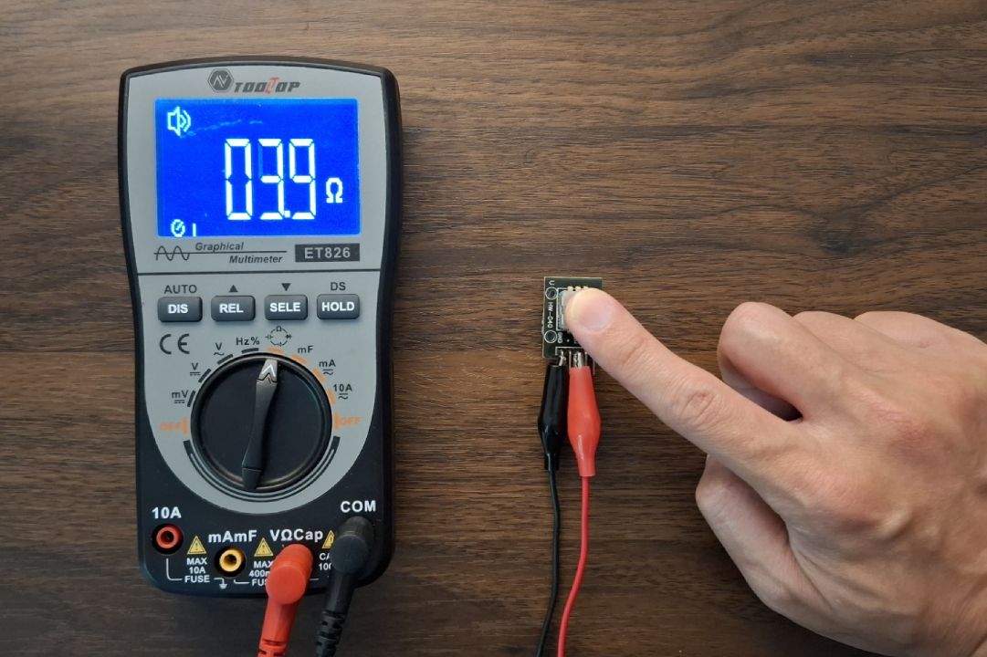
The button of the encoder works just like any button. It create a connection between SW pin and GND pin when it is pressed. Simply connect the pin to any digital pin, define it as INPUT_PULLUP, and apply a debouncing strategy like discussed in intro to embedded programming.

Below is a simple example of a counter program utilizing a rotary encoder. In short summary:
- Include the library
- Initialize a rotary object by defining the DT and CLK pin
- Attach two callback functions to rotary decoder method inside your sketch loop function
// 1. Include our rotary encoder library
#include "Rotary_Encoder.h"

#define DT 3
#define CLK 2

// 2. Initialize a rotary object
Rotary_Encoder rotary(DT, CLK);

void setup(){
  Serial.begin(9600);
}

void loop(){
    // 3. Loop rotary decoder with two callback functions as parameters
    // First callback will be triggered for clockwise rotation
    // Second for counter clockwise rotation
    rotary.decode(&countUp, &countDown);
}

int counter = 0;

// Count up function that is referenced as clockwise callback in the decoder above
void countUp() {
  counter++;
  Serial.print("Count up: ");
  Serial.println(counter);
}

// Count down function that is referenced as counter clockwise callback in the decoder above
void countDown() {
  counter--;
  Serial.print("Count down: ");
  Serial.println(counter);
}