Custom OLED Menu with Adafruit SSD1306
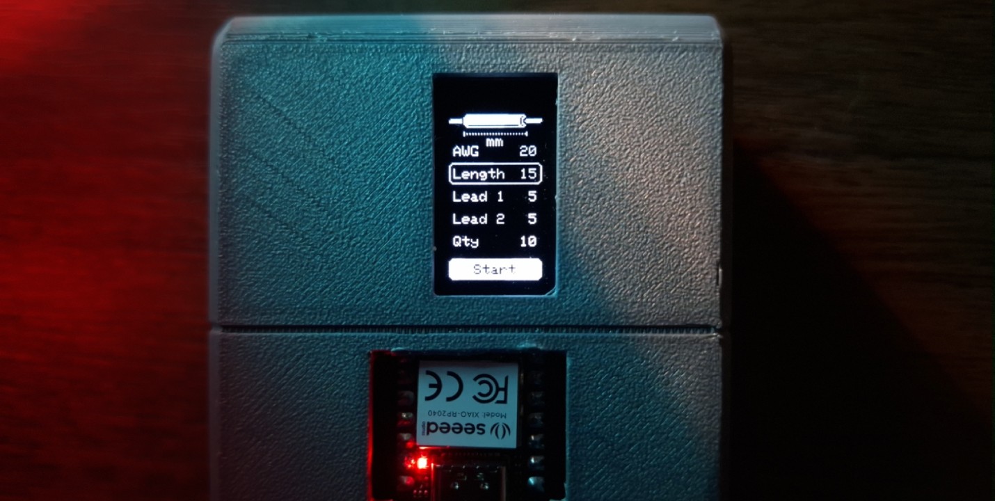
Another echo from the previous assignments, in this article we will be looking on how to design a simple user interface on a 0.96" OLED display through I2C communication and controlled by a rotary encoder. This user interface was used in the mechanical / machine design assignment.
Just like shown in the machine design assignment, the small display can be used more than just to show statuses. It is a little bit small, but it is adequate enough to be used for a small menu system. The Adafruit SSD1306 library doesn't seems like to have a menu system built into it, but with all the drawing functions it provides, we could build our own. The menu interface we will be making is inspired by a YouTube tutorial by Upir where he recreated a menu interface inspired by Flipper Zero user interface.
Preplanning and Designing the Interface
Before we start programming our menu, ideally we would need to have the design ready. But even before that, we should plan it out first. What's required to be shown on the display? What kind of interaction can the user do with it? What can the user change from the menu? What will indicate the user action?
For the wire stripping machine, it's purpose is to automatically strip and cut wire, therefore the ideal user interface should consist of but not limited to:
- Indicator of what type or what wire gauge
- User ability to traverse between parameters and change the value
- A parameter to set the quantity and length of wire to be cut
- Parameters to set the length of wire to be stripped
- A control button to start the operation
- Progress indicator showing how many wires has been cut
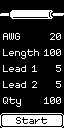
By having a clear requirements defined, it'll make designing the interface itself much easier. Because we are working with such a small display, we can easily design it in a raster image editor pixel by pixel. This particular OLED can only have on and off pixel, there is no in-between. Therefore when we design the interface, the pixels need to be pure black #000000 or pure white #FFFFFF. Below is the design for the wire stripping machine done in Photopea.
Programming the Interface
Judging from the design, we can separate it into 3 graphic categories: parameters, indicators, and button. We can create a function - let's call this function displayUpdate - to encapsulate multiple functions, each for drawing those categories. This main function will be triggered every time the user interacted with the input or when there is a feedback from the machine.
Applying the workflow discussed in output device assignment, the function need to trigger clearDisplay function at the start and trigger display function at the end. Because there are some black colored text in the design, we will need to reset the color back to white before we start drawing any of the elements.
void displayUpdate() {
  display.clearDisplay();
  display.setTextColor(SSD1306_WHITE);

  drawParameters();
  drawIndicators();
  drawButton();

  display.display();
}
Parameter Arrays
If we look at the menu itself, we can see that it mainly consists of key value pair with identical UI elements and mostly identical interaction. Instead of drawing the parameters individually, we could utilize 2 arrays, one to hold the key - let's name it parameters - and the other for the values.
To indicate which parameter is highlighted, we could define a cursor variable where it could be referenced as array index. We also need to know whether the user is selecting a parameter or not, so lets define a boolean variable for that and name it selected. Then we only need to program our input to increment or decrement the cursor to traverse the menu and toggling the selected to indicate if the parameter is selected or not.
const byte parameter_length = 5;

const char *parameters[parameter_length] = {
  "AWG",
  "Length",
  "Lead 1",
  "Lead 2",
  "Qty"
};

byte values[parameter_length] = {
  20,
  15,
  5,
  5,
  10
};

byte cursor = 1;
bool selected = false;
Draw Parameters
Inside the drawPrameters function, we can create a for loop with the same length as the arrays. This will give us an index (i) that we can use on parameters and values array to get the name and value of each loop.
#define OFFSET 29

void drawParameters() {
  for (int i = 0; i < parameter_length; i++) {
    // Draw rectangle if parameter is highlighted or selected
    // Print parameter name
    // Print parameter value
  }
}
Each parameter consists of 3 user interface elements: a rectangle if the parameter is highlighted or selected, text for the parameter name, and text for parameter value. If the cursor is equal to current index, then we need to draw a rounded rectangle by triggering drawRoundRect or fillRoundRect when the selected is true. The y coordinate for each of the rectangle has to be calculated on each loop based on the i. We also need to trigger setTextColor to black if the parameter is selected.
int y = OFFSET + (i * 16);

if (cursor == i) {
  if (selected) {
    display.fillRoundRect(0, y, display.width(), 15, 3, SSD1306_WHITE);
    display.setTextColor(SSD1306_BLACK);
  } else {
    display.drawRoundRect(0, y, display.width(), 15, 3, SSD1306_WHITE);
  }
}
Next we need to print our parameter name and value. We simply need to trigger setCursor with a coordinates then print the parameter name. Ideally we want the parameter value to be aligned to the left, but unfortunately this library did not include any text alignment functionality. By default all text will be printed aligned to the left. Luckily it's not too complicated to program one.
display.setCursor(3, y + 4);
display.print(parameters[i]);
printRg(String(values[i]), 3, y + 4);
Create a function called printRg with 3 parameters: one for the text string, the other for x and y coordinates. Next we just need to calculate the width of the text using getTextBounds and use is to calculate a new coordinate. Use those calculated coordinate for setCursor, then simply print the parameter value.
void printRg(const String &buf, int16_t x, int16_t y) {
  int16_t x1, y1;
  uint16_t w, h;
  display.getTextBounds(buf, x, y, &x1, &y1, &w, &h); //calculate width of new string
  display.setCursor((display.width() - x - w), y);
  display.print(buf);
}
Below is the completed drawParameters function. Note that if the current i is selected, we need to reset the text color to white otherwise the text on subsequent loop will stay black colored.
#define OFFSET 29

void drawParameters() {
  for (int i = 0; i < parameter_length; i++) {
    int y = OFFSET + (i * 16);

    if (cursor == i) {
      if (selected) {
        display.fillRoundRect(0, y, display.width(), 15, 3, SSD1306_WHITE);
        display.setTextColor(SSD1306_BLACK);
      } else {
        display.drawRoundRect(0, y, display.width(), 15, 3, SSD1306_WHITE);
      }
    }

    display.setCursor(3, y + 4);
    display.print(parameters[i]);
    printRg(String(values[i]), 3, y + 4);

    if (selected)
      display.setTextColor(SSD1306_WHITE);
  }
}

void printRg(const String &buf, int16_t x, int16_t y) {
  int16_t x1, y1;
  uint16_t w, h;
  display.getTextBounds(buf, x, y, &x1, &y1, &w, &h); //calculate width of new string
  display.setCursor((display.width() - x - w), y);
  display.print(buf);
}
Draw Bitmap Indicators
Unfortunately Adafruit SSD1306 doesn't have a function to read an image file. To add any custom graphical elements, we will need to encode them into array of hex values. To do that, we can simply export our graphics into .png files and convert them at image2cpp. Below are the arrays generated from the wire illustration and it's indicators:
// 'illustration', 64x9px
const unsigned char bm_wire [] PROGMEM = {
  0x00, 0x0f, 0xff, 0xff, 0xff, 0xff, 0xf0, 0x00, 0x00, 0x1f, 0xff, 0xff, 0xff, 0xff, 0xd8, 0x00,
  0x00, 0x3f, 0xff, 0xff, 0xff, 0xff, 0xb0, 0x00, 0x7f, 0xbf, 0xff, 0xff, 0xff, 0xff, 0xa7, 0xff,
  0xff, 0xbf, 0xff, 0xff, 0xff, 0xff, 0xaf, 0xff, 0xff, 0xbf, 0xff, 0xff, 0xff, 0xff, 0xa7, 0xfe,
  0x00, 0x3f, 0xff, 0xff, 0xff, 0xff, 0xb0, 0x00, 0x00, 0x18, 0x00, 0x00, 0x00, 0x00, 0xd8, 0x00,
  0x00, 0x0f, 0xff, 0xff, 0xff, 0xff, 0xf0, 0x00
};
// 'lead-indicator', 11x3px
const unsigned char bm_lead [] PROGMEM = {
  0x80, 0x20, 0xaa, 0xa0, 0x80, 0x20
};
// 'length-indicator', 44x3px
const unsigned char bm_length [] PROGMEM = {
  0x80, 0x00, 0x00, 0x00, 0x00, 0x10, 0xaa, 0xaa, 0xaa, 0xaa, 0xaa, 0xb0, 0x80, 0x00, 0x00, 0x00,
  0x00, 0x10
};
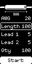
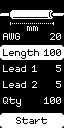
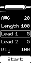
We can draw those graphics by triggering drawBitmap. In the drawIndicators function, we should also check the cursor value to draw certain indicator only when certain parameter is highlighted.
void drawIndicators() {
  display.drawBitmap(0, 11, bm_wire, display.width(), 9, 1);

  if (cursor == 1) {
    display.drawBitmap(10, 23, bm_length, 44, 3, 1);
    printCtr("mm", 0, 26);
  }

  if (cursor == 2)
    display.drawBitmap(0, 23, bm_lead, 11, 3, 1);

  if (cursor == 3)
    display.drawBitmap(53, 23, bm_lead, 11, 3, 1);
}
Draw Button
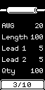
The button is fairly similar to the parameter omitting the for loop. It need a filled rounded rectangle as background and an indicator when the button is highlighted. The only difference is an additional processing boolean indicating if the machine is running or idling. If it is running, then it will show how much wire it has cut out of the amount it was programmed to cut. Otherwise it will simply print "Start".
Just like the parameter, we need to create a new function printCtr for aligning text to the center. It is pretty much identical to printRg with the exception of the cursor coordinate calculation.
extern bool processing;
extern unsigned int qty;

void drawButton() {
  display.fillRoundRect(0, 113, display.width(), 15, 3, SSD1306_WHITE);

  if (cursor == parameter_length)
    display.drawRoundRect(1, 114, display.width() - 2, 13, 3, SSD1306_BLACK);

  display.setTextColor(SSD1306_BLACK);

  if (processing) {
    String processed = String(values[4] - qty) + "/" + String(values[4]);
    printCtr(processed, 0, 117);
  } else {
    printCtr("Start", 0, 117);
  }

  display.setTextColor(SSD1306_WHITE);
}

void printCtr(const String &buf, int16_t x, int16_t y) {
  int16_t x1, y1;
  uint16_t w, h;
  display.getTextBounds(buf, x, y, &x1, &y1, &w, &h); //calculate width of new string
  display.setCursor((x + (display.width() - w) / 2), y);
  display.print(buf);
}
Summary
Below are all the interface programming codes - that have been abstracted into a tab - and a video showing it working on an OLED display with a rotary encoder. You can read the complete implementation on the mechanical / machine design assignment where the main sketch utilize mutates cursor, selected, and processing values when turn or click the knob.
/* menu.h */
#ifndef MENU_H
#define MENU_H
#include <Arduino.h>
#include <Wire.h>
#include <Adafruit_GFX.h>
#include <Adafruit_SSD1306.h>

extern Adafruit_SSD1306 display;
extern bool selected;
extern byte cursor;
extern byte values[];
extern const byte parameter_length;

bool displayBegin();
void displayUpdate();
void drawIndicators();
void drawParameters();
void drawButton();
void printCtr(const String &buf, int16_t x, int16_t y);
void printRg(const String &buf, int16_t x, int16_t y);

#endif

// -----------------------------------------------------------------------------------------------

/* menu.cpp */
#include "menu.h"

#define SCREEN_I2C_ADDR 0x3C // or 0x3C
#define SCREEN_WIDTH 128     // OLED display width, in pixels
#define SCREEN_HEIGHT 64     // OLED display height, in pixels
#define OLED_RST_PIN -1      // Reset pin (-1 if not available)

Adafruit_SSD1306 display(SCREEN_WIDTH, SCREEN_HEIGHT, &Wire, OLED_RST_PIN);

const byte parameter_length = 5;

const char *parameters[parameter_length] = {
  "AWG",
  "Length",
  "Lead 1",
  "Lead 2",
  "Qty"
};

byte values[parameter_length] = {
  20,
  15,
  5,
  5,
  10
};

byte cursor = 1;
bool selected = false;

bool displayBegin() {
  // SSD1306_SWITCHCAPVCC = generate display voltage from 3.3V internally
  bool initialized = display.begin(SSD1306_SWITCHCAPVCC, SCREEN_I2C_ADDR);

  if (initialized) {
    display.setRotation(1);
    displayUpdate();
  }

  return initialized;
}

void displayUpdate() {
  display.clearDisplay();
  display.setTextColor(SSD1306_WHITE);

  drawIndicators();
  drawParameters();
  drawButton();

  display.display();
}

// 'illustration', 64x9px
const unsigned char bm_wire [] PROGMEM = {
  0x00, 0x0f, 0xff, 0xff, 0xff, 0xff, 0xf0, 0x00, 0x00, 0x1f, 0xff, 0xff, 0xff, 0xff, 0xd8, 0x00,
  0x00, 0x3f, 0xff, 0xff, 0xff, 0xff, 0xb0, 0x00, 0x7f, 0xbf, 0xff, 0xff, 0xff, 0xff, 0xa7, 0xff,
  0xff, 0xbf, 0xff, 0xff, 0xff, 0xff, 0xaf, 0xff, 0xff, 0xbf, 0xff, 0xff, 0xff, 0xff, 0xa7, 0xfe,
  0x00, 0x3f, 0xff, 0xff, 0xff, 0xff, 0xb0, 0x00, 0x00, 0x18, 0x00, 0x00, 0x00, 0x00, 0xd8, 0x00,
  0x00, 0x0f, 0xff, 0xff, 0xff, 0xff, 0xf0, 0x00
};
// 'lead-indicator', 11x3px
const unsigned char bm_lead [] PROGMEM = {
  0x80, 0x20, 0xaa, 0xa0, 0x80, 0x20
};
// 'length-indicator', 44x3px
const unsigned char bm_length [] PROGMEM = {
  0x80, 0x00, 0x00, 0x00, 0x00, 0x10, 0xaa, 0xaa, 0xaa, 0xaa, 0xaa, 0xb0, 0x80, 0x00, 0x00, 0x00,
  0x00, 0x10
};

void drawIndicators() {
  display.drawBitmap(0, 11, bm_wire, display.width(), 9, 1);

  if (cursor == 1) {
    display.drawBitmap(10, 23, bm_length, 44, 3, 1);
    printCtr("mm", 0, 26);
  }

  if (cursor == 2)
    display.drawBitmap(0, 23, bm_lead, 11, 3, 1);

  if (cursor == 3)
    display.drawBitmap(53, 23, bm_lead, 11, 3, 1);
}

#define OFFSET 29

void drawParameters() {
  for (int i = 0; i < parameter_length; i++) {
    int y = OFFSET + (i * 16);

    if (cursor == i) {
      if (selected) {
        display.fillRoundRect(0, y, display.width(), 15, 3, SSD1306_WHITE);
        display.setTextColor(SSD1306_BLACK);
      } else {
        display.drawRoundRect(0, y, display.width(), 15, 3, SSD1306_WHITE);
      }
    }

    display.setCursor(3, y + 4);
    display.print(parameters[i]);
    printRg(String(values[i]), 3, y + 4);

    if (selected)
      display.setTextColor(SSD1306_WHITE);
  }
}

extern bool processing;
extern unsigned int qty;

void drawButton() {
  display.fillRoundRect(0, 113, display.width(), 15, 3, SSD1306_WHITE);

  if (cursor == parameter_length)
    display.drawRoundRect(1, 114, display.width() - 2, 13, 3, SSD1306_BLACK);

  display.setTextColor(SSD1306_BLACK);

  if (processing) {
    String processed = String(values[4] - qty) + "/" + String(values[4]);
    printCtr(processed, 0, 117);
  } else {
    printCtr("Start", 0, 117);
  }

  display.setTextColor(SSD1306_WHITE);
}

void printCtr(const String &buf, int16_t x, int16_t y) {
  int16_t x1, y1;
  uint16_t w, h;
  display.getTextBounds(buf, x, y, &x1, &y1, &w, &h); //calculate width of new string
  display.setCursor((x + (display.width() - w) / 2), y);
  display.print(buf);
}

void printRg(const String &buf, int16_t x, int16_t y) {
  int16_t x1, y1;
  uint16_t w, h;
  display.getTextBounds(buf, x, y, &x1, &y1, &w, &h); //calculate width of new string
  display.setCursor((display.width() - x - w), y);
  display.print(buf);
}