Application and Implication
H2Gen
Fab Lab Bali's current flagship initiative is Hydrogen Village, a continuation and expansion of Balon-Balon Ijo, one of the Fab Island Challenge from Bali Fab Fest 2022. This initiative aims to aid Bali's attempt to achieve net zero emission by 2045 by introducing the application of hydrogen gas as a renewable energy source.
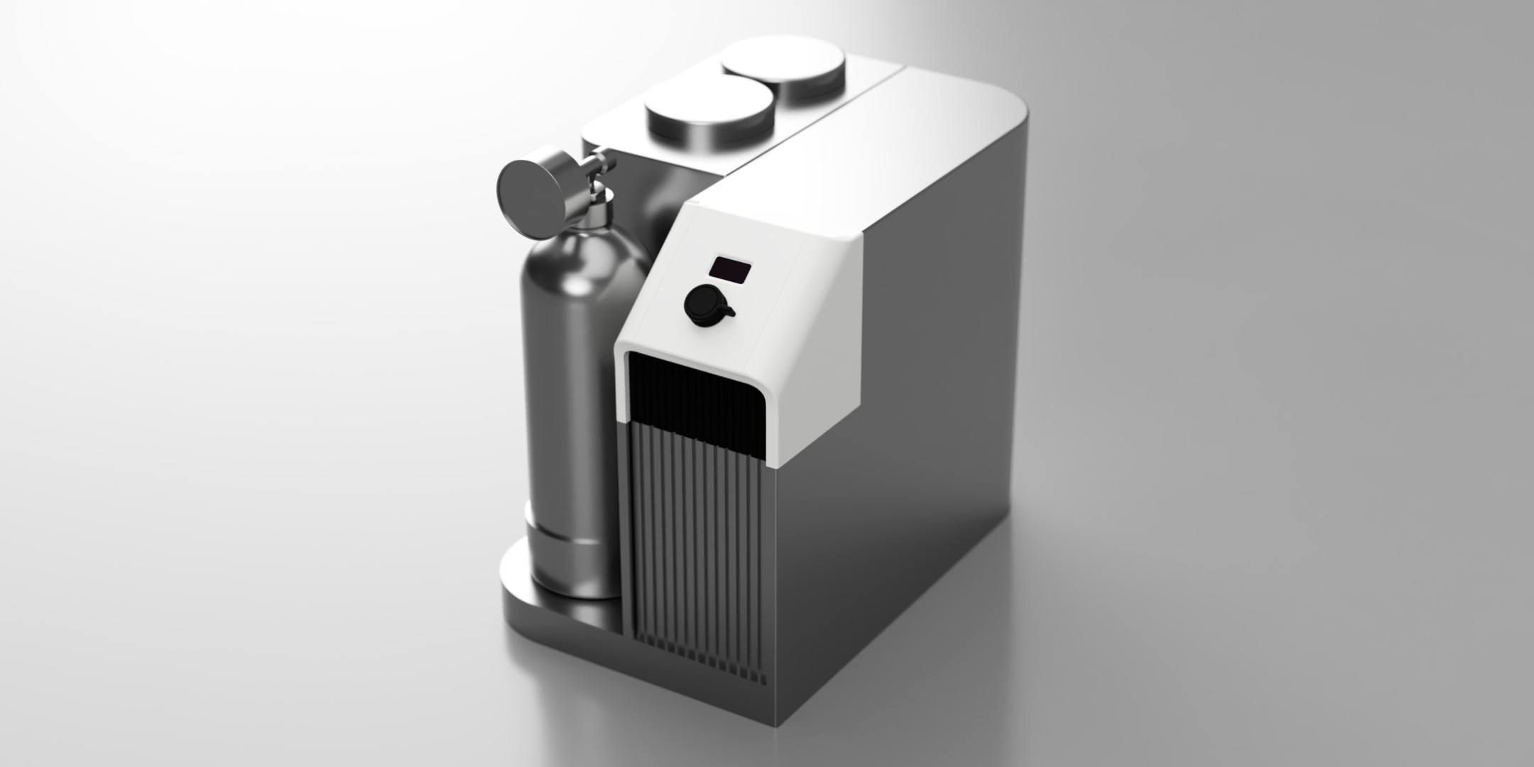
My goal is to design a compact automated hydrogen generator for household or small neighborhood scale, I call it H2Gen. The heart of the device is an alkaline electrolyser that generates hydrogen from sea water that will be stored and compressed automatically into an aluminum canister. Ideally this device should be powered by solar energy.
Unfortunately the complexity of the project is rather high and not to mention we are working with a very reactive gas. With that consideration on top of the little time that we have left, I decided to focus only on the automation controller module as it fulfils all the requirement as a final project.
References
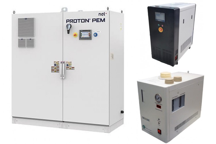
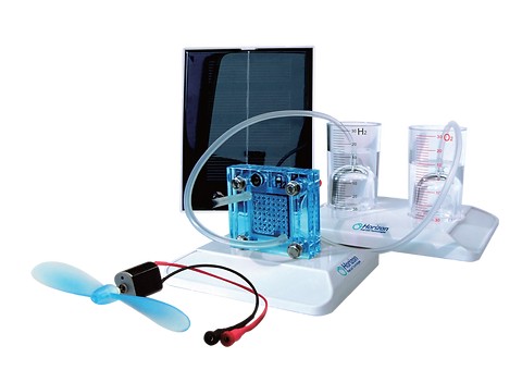
Hydrogen generators already commercially available, but they are mostly industrial scale, specifically design for lab purpose only, or only a simple education demo kit. There is still a market gap for consumer level hydrogen generator.
However, there are several people attempting to design similar device that I have in mind. In fact, there is a final project from past student Antero Metso that attempt to create something similar. All these devices have the same goal of generating hydrogen safely through electrolysis process, but each of them have their own unique approach. Below are some notable projects that I found:
Automated Hydrogen Generator
By far this project by a YouTuber named Hyperspace Pirate is the closest project to what I have in mind for my project. He explained the science in detail and explained his thought throughout the design process. He also design a very unique electrolysis cell using 3D printed parts. This cell is essentially a HHO generator that is cleverly designed to separate the hydrogen and oxygen.
Homemade Hydrogen Generator and Compressor Unit
A similar project done by a YouTuber named The DIY Science Guy. He has a series of them detailing how he design the generator, some upgrades done to it, and the reasoning behind those upgrades. He design an automation system that use mechanical switches instead of using a micro-controller. Another interesting part is he design a stacked HHO generator that use a kitchen towel to separate the hydrogen and oxygen. Although it eventually got replaced by other material, the cell has ran for hundreds of hours before the towel need to be replaced.
The Volks-Electrolyzer
They are an initiatives aims to enable a hydrogen economy by collecting and consolidating prices and technical data globally on most components used in a hydrogen system. They also design various hydrogen kits, held trainings and workshops, and actively shared their research to their community. You can join and access these resources by registering a membership with a reasonably affordable price.
Design Overview
Following the distributed innovation principle, this device will be designed using as little specialized components as possible, utilizing mainly digital fabrication tools, and using materials that are relatively easier to source anywhere. This way the project can be easily replicated in other places and bringing positive impact especially to people living in coastal area.
Questions
I am not an engineer, chemist, nor scientist. I am simply a curious designer that like to learn many technical things. Before this program, I only know vaguely about hydrogen from my highschool chemistry class, only ever tried soldering once in my live, and have failed multiple time trying to teach myself electronic design. So I have plenty of questions need to be answered to design this device.
The obvious question will be how do you generate hydrogen? Which type og electrolyser do I want to use? How do you dry the hydrogen generated from water? How do you want to store the hydrogen? What compressor can you use for compressing reactive gas like hydrogen? What can we use for the temporary gas buffer? What components are needed for the pneumatic system? Those are questions for the hydrogen part itself that won't be covered in my final project because as mentioned previously, I'll focus on designing only the controller module for now.
For the controller there are some questions regarding the electronic that I need to answer:
- What input can I use to detect when the gas buffer is full or empty?
- How can we control the electrolyser, compressor, and solenoid valve with a small micro-controller?
- How will I power the whole system?
MVP System
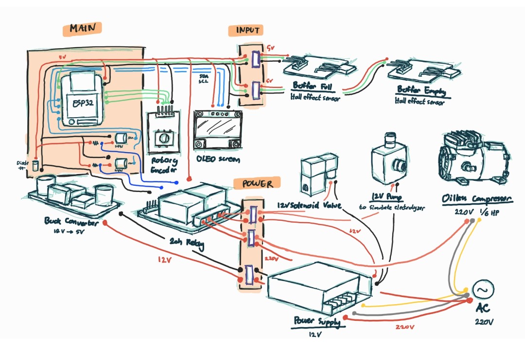
For the controller, I am going to design it with modularity in mind. Ideally the controller should be attached with multiple sensors, peripherals, and output devices to give more robust features. However, for the interest of time, I will be developing a MVP (minimum viable product) version of it, or we could simply label it as lite version or spiral 1. Below is a video showing a simple test of the minimum system and the breakdown of how it works:
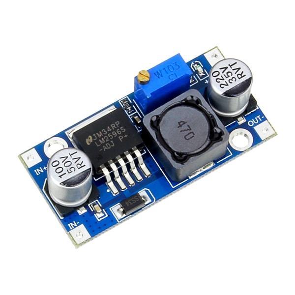
- The controller will be powered by a 12 V power supply connected to 220 V AC power. The controller will use a DC buck converter to lower the voltage to 5 V to power the micro-controller. The other devices will be power directly from the power supply or from AC power.
- Because hydrogen molecule is really small, it is very hard to generate and compress it at the same time. It will be more effective to store the gas in buffer first, this demo use a simple latex balloon for that purpose. I also only use a simple air pump to simulate this process instead of generating real hydrogen from an electrolyser.
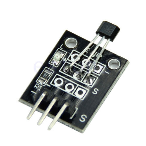
- A magnet is attached on top of the buffer that will trigger a hall effect sensor when the balloon reach certain volume. This will indicate to the controller that the buffer has been filled enough gas.
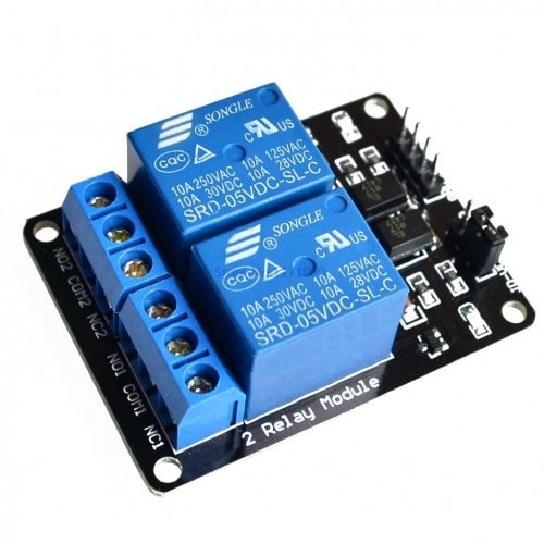
- The controller then will turn off the electrolyser (a pump in this demo), close a solenoid valve between the electrolyser and the buffer, then turn on an AC oil-less compressor to move the gas from the buffer to the canister. All these devices are controller by the controller through a relay switch.
- Once the buffer has been emptied, the same magnet will trigger another hall effect sensor to indicate that all the gas has been compressed. Then the controller will switch off the compressor, open the valve, and restart the electrolyser again.
- The cycle will run few times until the the canister has been filled with gas to about 5 bar of pressure. In the demo above, it only need 3 cycles to reach that. However, this will depends on the volume of the buffer used, therefore it will need to be recalculated once we have finalized the buffer design.
Electronics
Although Neil encourage us to make rather than buy the parts whenever possible, it might not be an option for me to make all the electronics myself for this project. As I have discussed in my multiple assignments, it's quite hard to come by certain components in Indonesia. Because of this reason, below are the electronic modules that I need to use for this project:
Other than those modules, I will design and fabricate the rest of the electronics that connect all those modules together. It will be designed in KiCad, fabricated using 3018 CNC milling machine, and stuffed by hand soldering. The same way I designed and fabricated my development board. To fully utilize the space inside my enclosure, I'm planning to divide my controller into 3 boards:
1. Main controller board
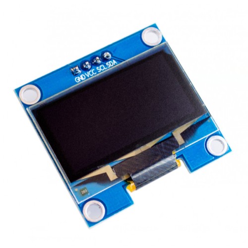
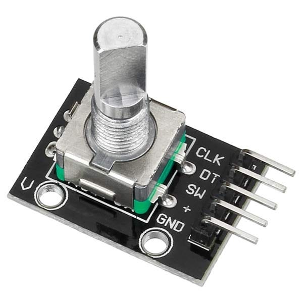
This will be the main board where the MCU will be plugged into. It will have JST connectors equipped with decoupling capacitors to connect to the screen, rotary encoder, and relay; another JST connector to connect to the inputs breakout board. There should be logic level shifter circuits using transistor to send high or low 5 V signal to the relay. And lastly a connector to receive power from the buck converter.
2. Inputs breakout board
This board consists of multiple JST ports for connecting with some input devices. Each port is equipped with a decoupling capacitors and a signal voltage divider. Then all the pins from those connectors will be consolidated to one JST connector that will be connected with the main board.
3. Power/relay breakout board
The simplest board out of the three will simply be an interface for the power lines. It consist of some terminals as an interface for the DC buck converter and relay module.
Enclosure
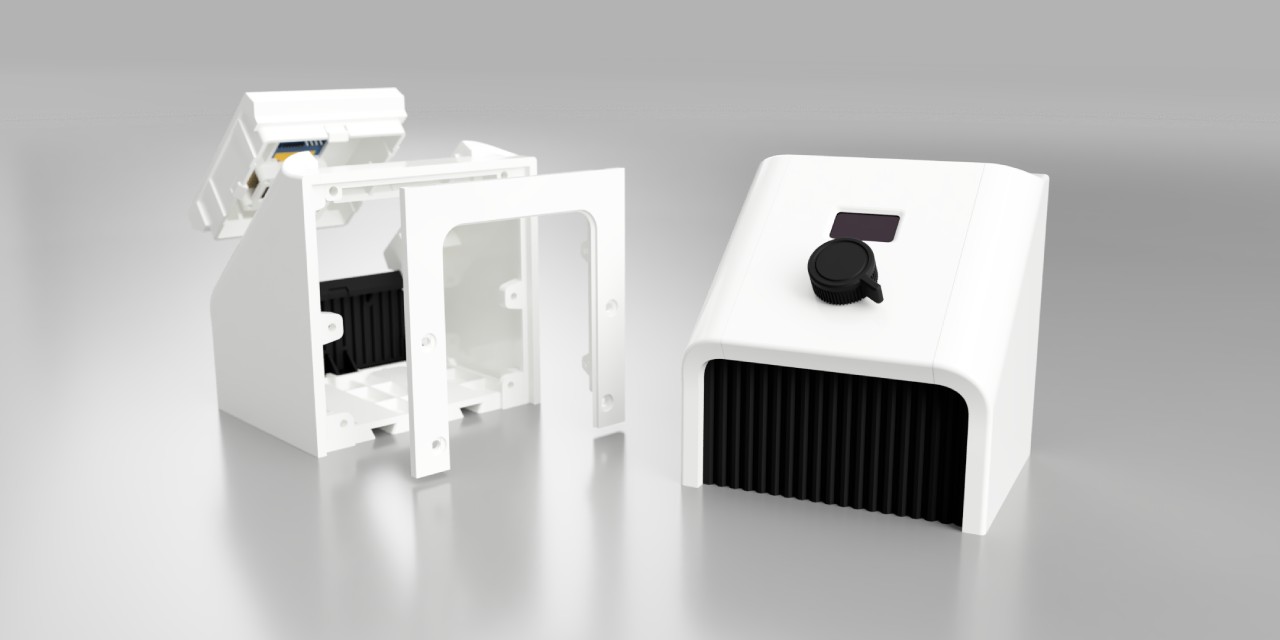
As discussed in my system integration assignment, the enclosure is designed mostly to be 3D printed. I print them using PLA, but may re-print them in PETG if the device need to be placed outdoor.
The internal structures are mostly flat, so they were fabricated out of 3 mm acrylic with a laser cutter. However, these structures can also be easily 3D printed.
All the components are assembled together with a combination of some snap fit mechanism, press fit joinery, and some screws. I simply design slightly undersize holes and let the machined screws thread into them. This works nicely, but will consider to add slots for nuts or using heat insert nut if I need to repeatedly assemble and disassemble this device.
Bill of Materials
Below is the list of components and materials for the controller unit. I source all the components from Tokopedia (basically Indonesia's equivalent of Amazon or Ebay). I also tried to source them from as little number of sellers as possible to reduce the shipping cost. Excluding that, the approximate total cost of the components and materials are IDR 336,920 or about USD 21.
| Quantity | Price | Total | |
|---|---|---|---|
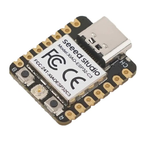
| XIAO ESP32-C3 | 1 | IDR 127.500 | IDR 127.500 |
| LM2596HVS Buck Converter | 1 | IDR 11,200 | IDR 11,200 |
| Relay 5V 2 channel | 1 | IDR 10,500 | IDR 10,500 |
| 0.96" OLED screen | 1 | IDR 26,500 | IDR 26,500 |
| KY-40 rotary encoder | 1 | IDR 6,500 | IDR 6,500 |
| KY-003 hall effect sensor | 2 | IDR 5,000 | IDR 10,000 |
| Female straight header - 7 pin | 2 | IDR 700 | IDR 1,400 |
| JST XH right angle - 2 pin | 1 | IDR 1,000 | IDR 1,000 |
| JST XH right angle - 3 pin | 4 | IDR 1,500 | IDR 6,000 |
| JST XH right angle - 4 pin | 1 | IDR 2,000 | IDR 2,000 |
| JST XH right angle - 5 pin | 1 | IDR 2,500 | IDR 2,500 |
| JST XH right angle - 7 pin | 2 | IDR 3,000 | IDR 7,000 |
| JST XH straight - 4 pin | 1 | IDR 1,700 | IDR 1,700 |
| KF2EDG right angle terminal block - 2 pin | 3 | IDR 2,500 | IDR 7,500 |
| Screw terminal block - 2 pin | 3 | IDR 1,750 | IDR 5,250 |
| Capacitor 1206 - 100 nF | 7 | IDR 400 | IDR 2,800 |
| Resistor 1206 - 1 kΩ | 14 | IDR 150 | IDR 2,100 |
| Resistor 1206 - 470 Ω | 2 | IDR 150 | IDR 300 |
| Transistor NPN SOT-23 | 2 | IDR 400 | IDR 800 |
| Schottky Diode | 1 | IDR 250 | IDR 250 |
| Signal cable | 1 m | IDR 9,900 | IDR 9,900 |
| Cable 16 AWG | 20 cm | IDR 9,500 / m | IDR 1,900 |
| Cable 18 AWG | 20 cm | IDR 6,500 / m | IDR 1,300 |
| Cable 20 AWG | 30 cm | IDR 4,500 / m | IDR 1,350 |
| M3 screw - 6 mm | 22 | IDR 400 | IDR 8,800 |
| M3 screw - 12 mm | 2 | IDR 400 | IDR 800 |
| M4 screw - 8 mm | 10 | IDR 500 | IDR 5,000 |
| M4 screw - 20 mm | 2 | IDR 650 | IDR 1,300 |
| M3 nylon spacer - 6 mm | 18 | IDR 590 | IDR 10,620 |
| FR1 PCB board - 10 x 10 cm | 1 | IDR 4,000 | IDR 4,000 |
| PLA filament | 350 g | IDR 154,000 / kg | IDR 53,900 |
| 3 mm Acrylic sheet - 10 x 15 cm | 150 cm2 | IDR 23 / cm2 | IDR 5,250 |
| Total | IDR 336,920 |
Further Development
As discussed before, this will be the MVP of a sub-system, only a fraction of the device I plan to build. That's why I intentionally design it in such a modular fashion. For example, the enclosure front and back panel can be easily be redesign to fit other devices without requiring to redesign the other panels.
Here are some additional components that I already had in mind for the device safety improvement or additional features:
- Emergency switch on the front panel
- Pressure transducer to measure shut off the device when the canister is full instead of current system that only use an approximation
- Current sensor to measure current draw by the electrolyser. We can use this data for analyzing the electrolysis process or shut the device down if there is a current overdraw
- Temperature probe to measure the liquid temperature. This can be used to shut the device down if we detect a thermal runaway
- Water level float sensor to detect if we have enough liquid in our reservoir
- Bigger screen for better display or even use touch screen to replace the rotary encoder
- Add web dashboard to display device status or data for analysis purpose. That's the main reason why I choose ESP32-C3 as the MCU, so I can easily add this feature in the future
- Limit switch to detect if the canister is plugged and placed correctly
- Buzzer, this might be minor thing but it will improve the user experience
Evaluation
The device as the whole can be seen as a success if manage to safely generate and store relatively pure hydrogen from water. For the controller module itself, it should be evaluated based on the automation, can it reliably detect when the buffer is full or empty to trigger the compressing sequence on and off.
As a product designer, another matrix that I think should be the main evaluation point is how easy this device can be replicated, assembled, and maintained. If the device works well but require hyper specialized components, then less people will want to build it. If it is hard to be fabricated, assembled, and maintained, then even less people will implement it.
I hope by designing it to only using components available in our local marketplace and the rest can be fabricated digitally using relatively cheap machines, many people in Indonesia will start to get interested in renewable energy. Indonesia is the largest archipelago nation in the world with more than 17,000 islands. Many still have limited access to electricity due to the significant investment required to build the infrastructure. Instead of waiting for that to ever happen, imagine if people can start to make this device, produce hydrogen from sea water, then use the gas as their energy source. That's wild.