Computed Aided Machining with Fusion 360
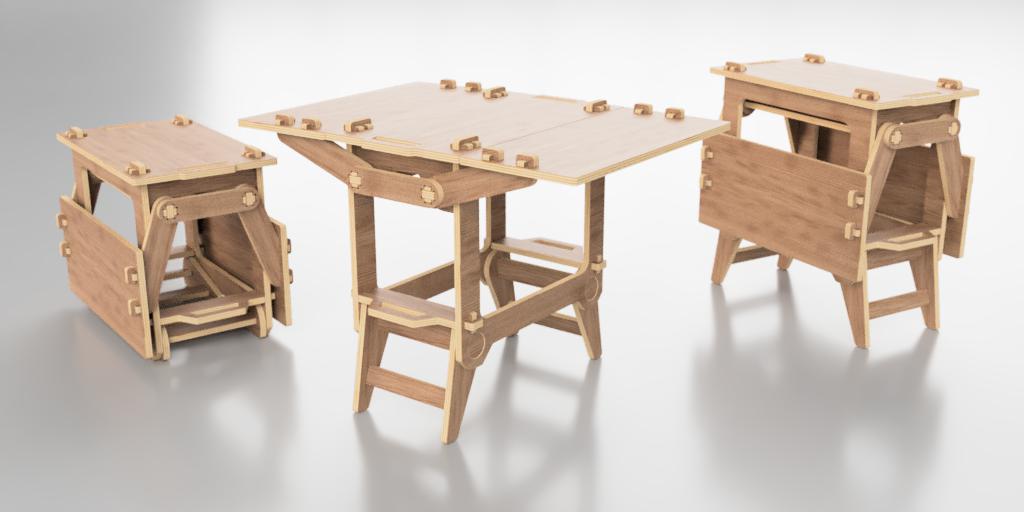
This project is a mobile workbench that can be compacted for easier transportability. The work surface is at 70 cm high and has dimensions of 68 x 100 cm. When compacted, it has outer dimensions of 68 x 46 x 53 cm. The inner frame has a space that can be used as storage with effective dimensions of 53 x 30 x 25 cm.
The design is inspired by some mobile camping equipment that can unfold into a full set kitchen. It is designed to be fabricated out of three-quarter sheets of 18 mm plywood using a CNC milling machine.
Modeling
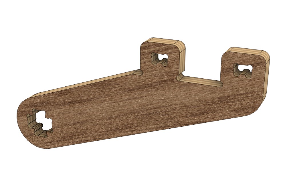
Although this workbench has quite a number of components, the modeling process is rather simple. All the components are modeled simply by creating a sketch, extruding, filleting edges, and occasionally mirroring.
Joinery
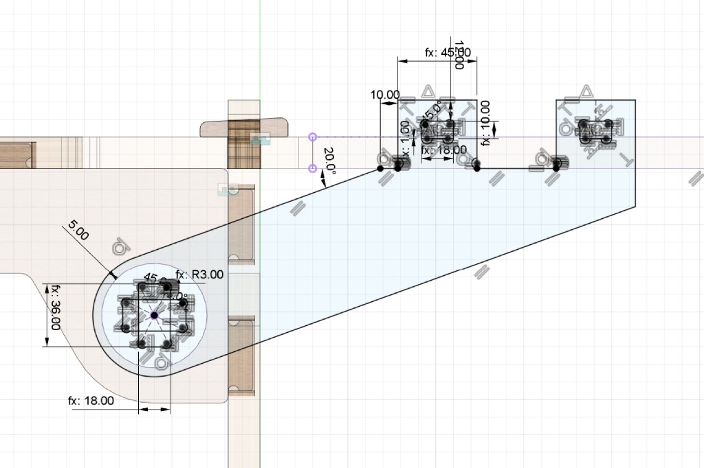
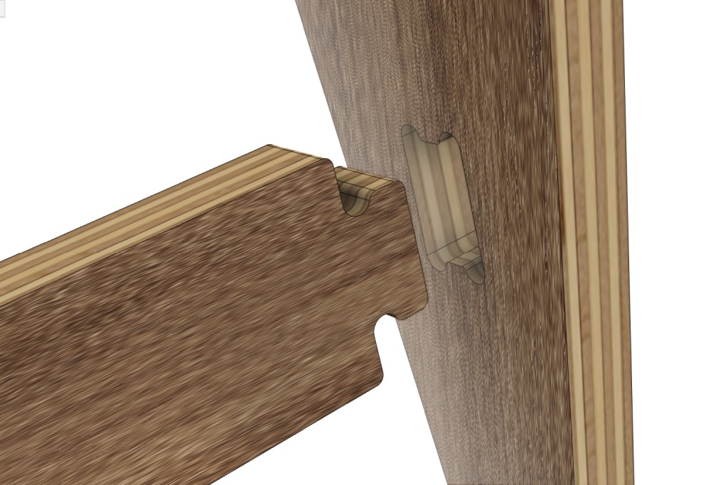
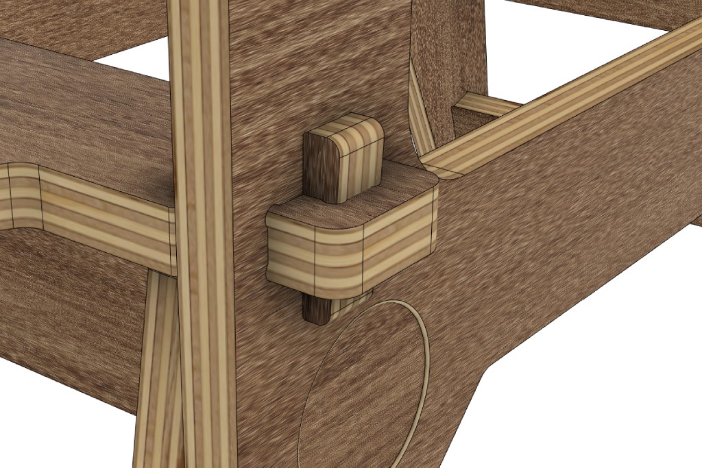
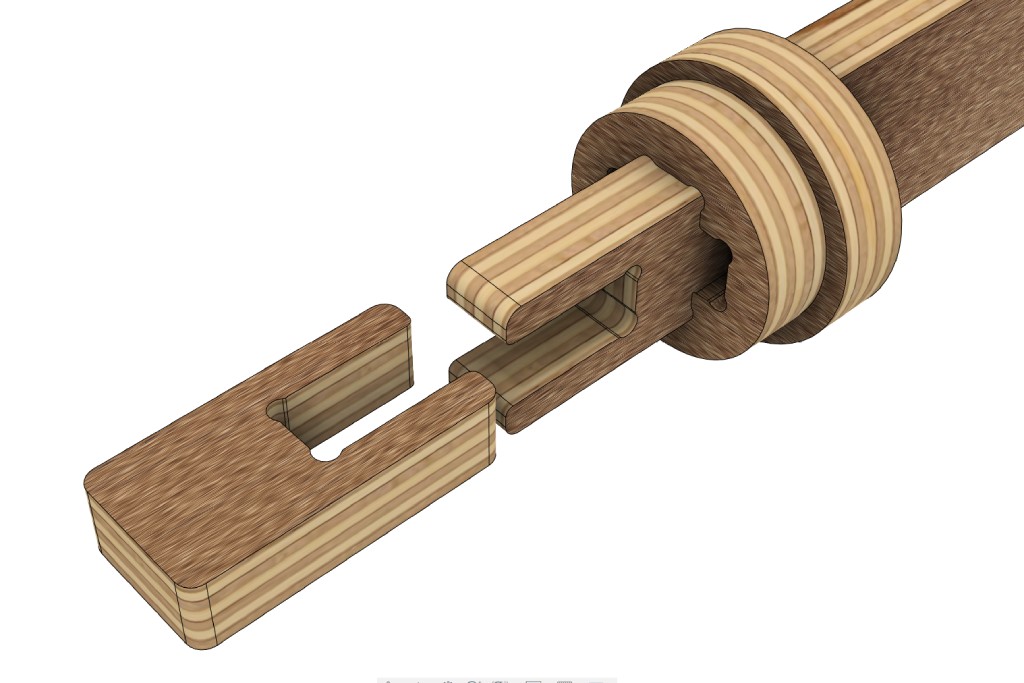
This design assembly does not require any glue or screws. Instead, it uses three types of woodworking joineries: blind mortise tenon joint, wedge joint, and half lap joint.
There are many other woodworking joineries that you could possibly make. However, other than the three joineries above, finger joint and dovetail joint are the most common joineries used in a woodworking project. Watch this excellent tutorial by Aribabox to learn how to design few other joineries that you could be fabricated with a CNC machine.
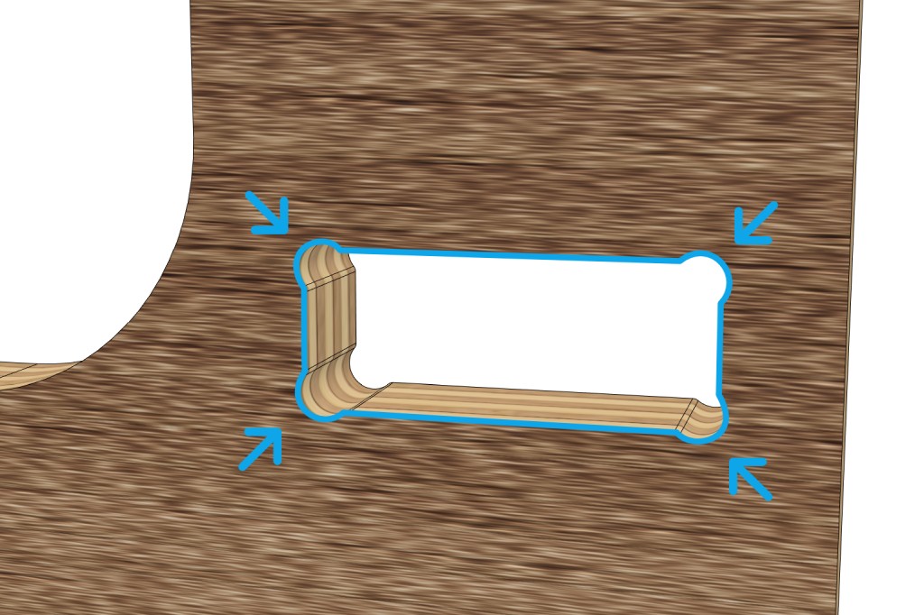
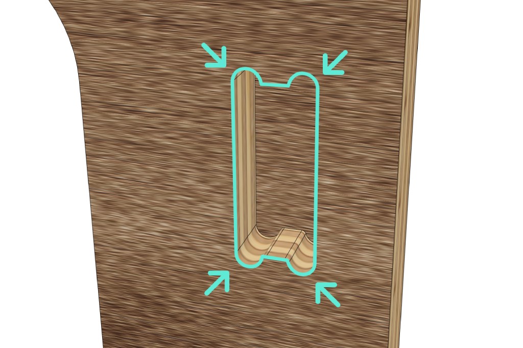
The only problem when fabricating these joineries with a CNC machine is that the machine could not cut an inside corner. It will leave a rounded corner with the same radius as the size of your milling bit, making it impossible to join the components together. You could do manual post-processing like demonstrated by Cristiana from Get Hands Dirty, or more commonly you could add dog-bone or t-bone fillets to mitigate this issue. Watch this tutorial to learn how to design them and when to use what.
CAM
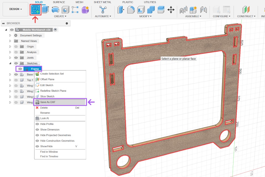
We can simply use MODS to generate toolpath the same way as milling PCB. To do this, simply use create sketch on a component to create a projection sketch of that component. Right click on the sketch and save it as DXF. Open the exported file in vector program such as Inkscape, then save it as SVG file.
MODS works just fine, but Fusion has some built in CAM (computer aided manufacturing) functionalities that makes generating toolpaths really easy. Because it also directly connected to the design environment, any design updates done will immediately reflected to the manufacturing workspace. This improve efficiency tremendously by eliminating the needs to keep exporting and importing files between multiple softwares.
Setup
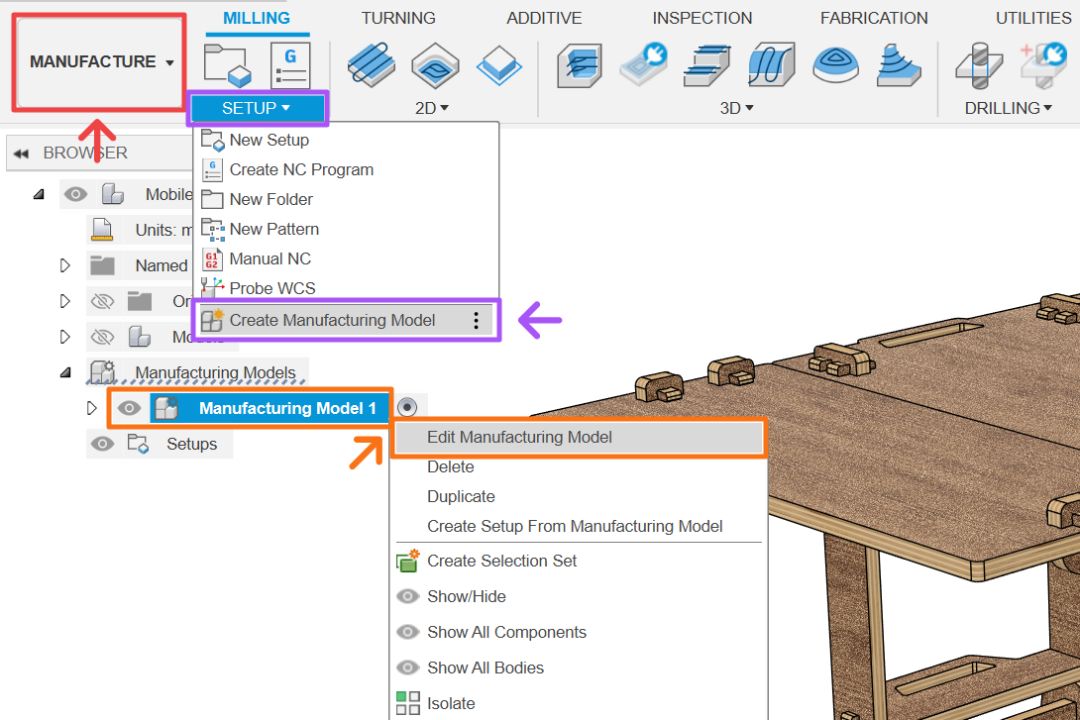
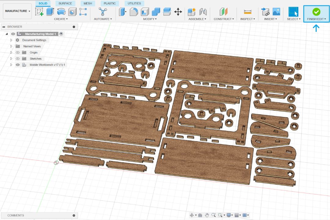
First go to manufacture workspace. The first thing you want to do is to create manufacturing model, essentially a duplicate of your model with all the constraints removed if it has some. Right click on the model and select edit manufacturing model. This will open a sub workspace identical to design workspace which allow us to laid out all the components flat using a combination of move and align tool.
Be mindful which direction your components are facing if it has some pocket - parts that did not need to be cut all the way through such as the blind mortise used in this design. You also need to account for your components orientation if you are cutting it out of material with grains such as wood. Once done, simply click finish edit and you will be back to manufacture workspace.
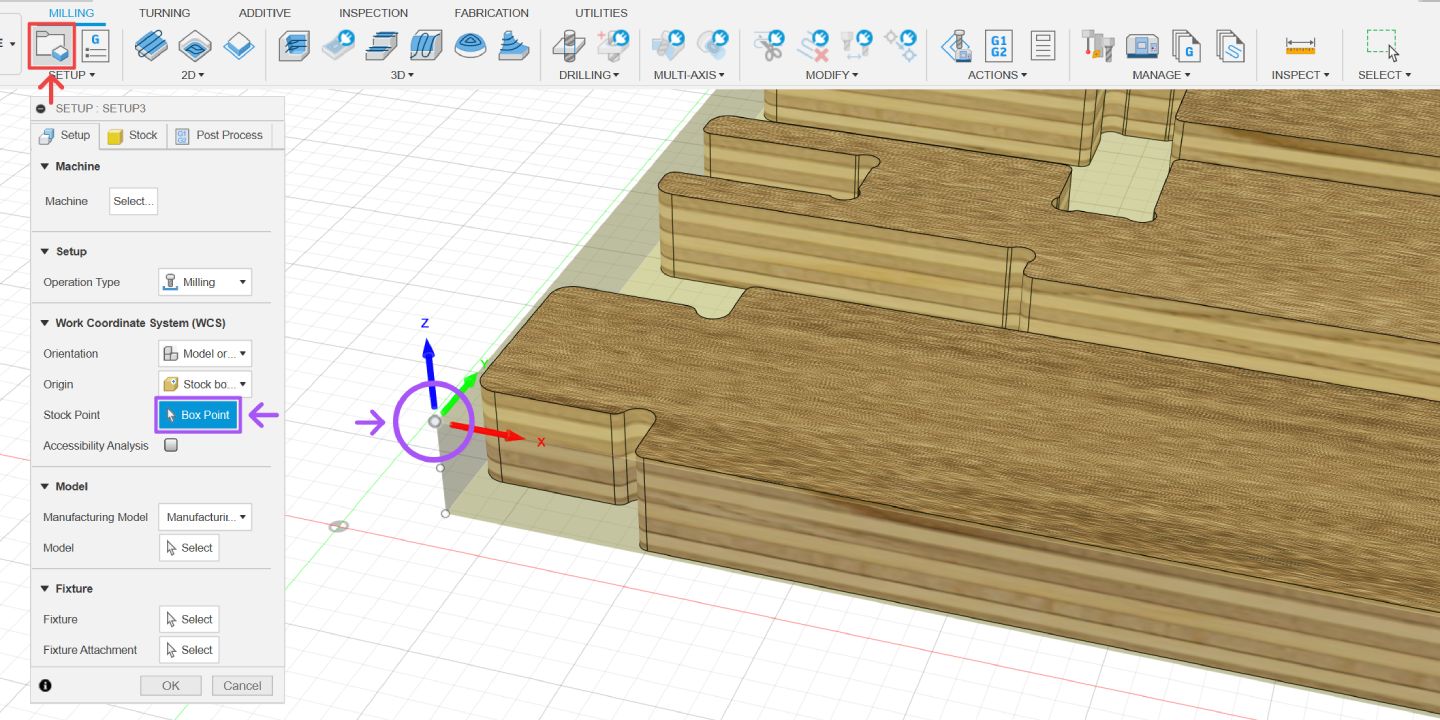
Next we want to create our setup. By default this tool will create a stock surrounding all our components shown with transparent yellow box over them. Setup the world coordinate system origin by selecting the upper lower left stock point. This essentially setting our 0, 0, 0 coordinate to that point. Adjust it accordingly with the machine you will be using.
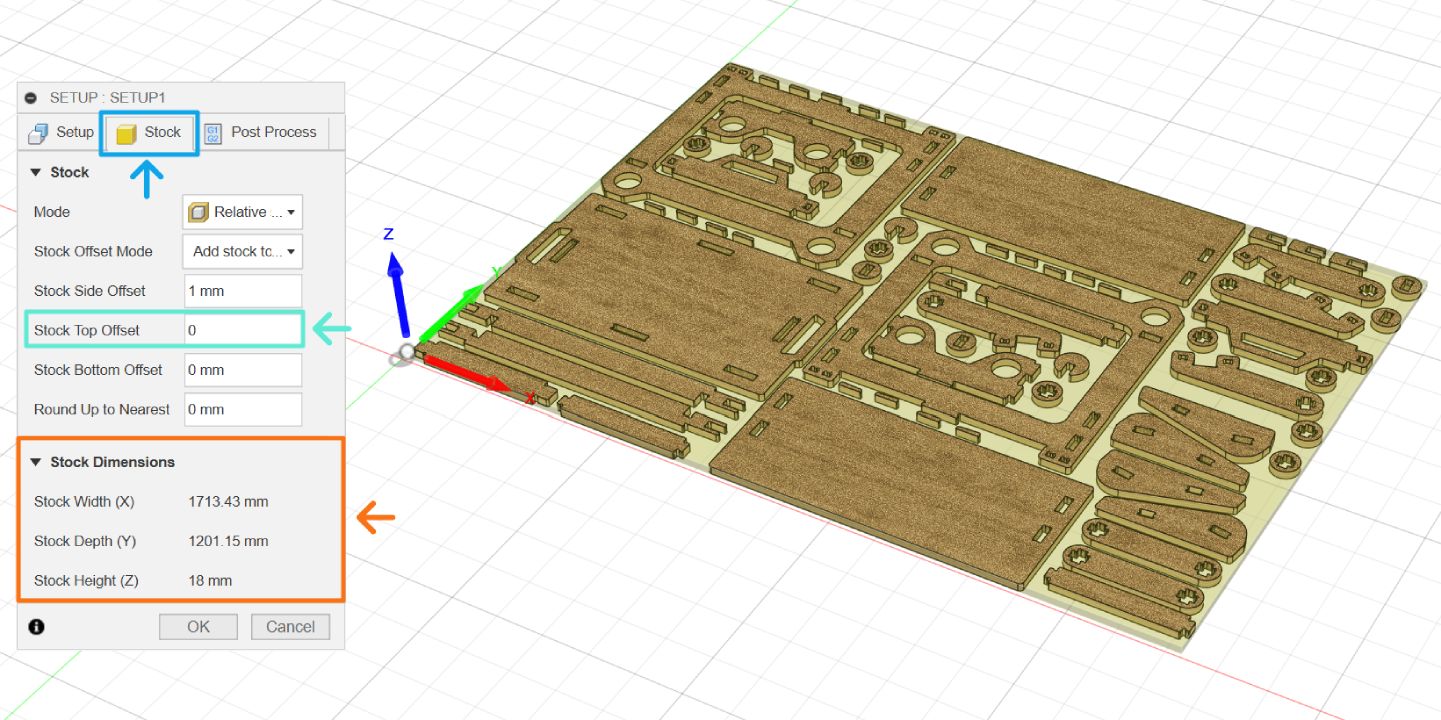
Go to the stock tab and you will be shown the stock dimensions required for the setup. This design will be milled out of 18 mm sheet, so we need to remove the default stock top offset by setting the value to 0.
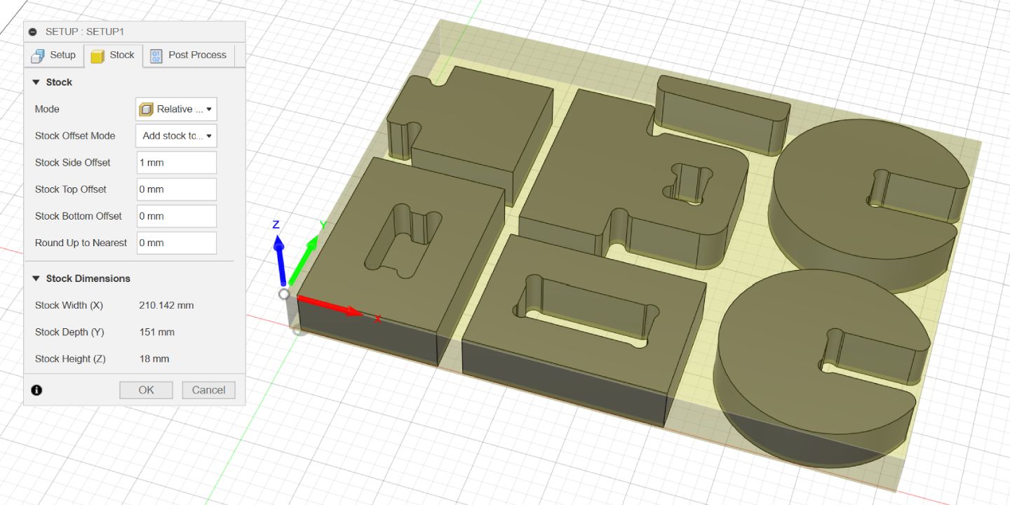
Now that the setup is done, we could setup the milling operations. Fusion has many operation types we could utilize, however this design in particular only need two types, 2D pocket and 2d contour. To illustrate the step, we will be looking on how to setup the operations on a set of simplified models of the joinery used in this design. This also serve the purpose of finding the right tolerance to be used for the particular combination of machine, milling bits, stock material, and design.
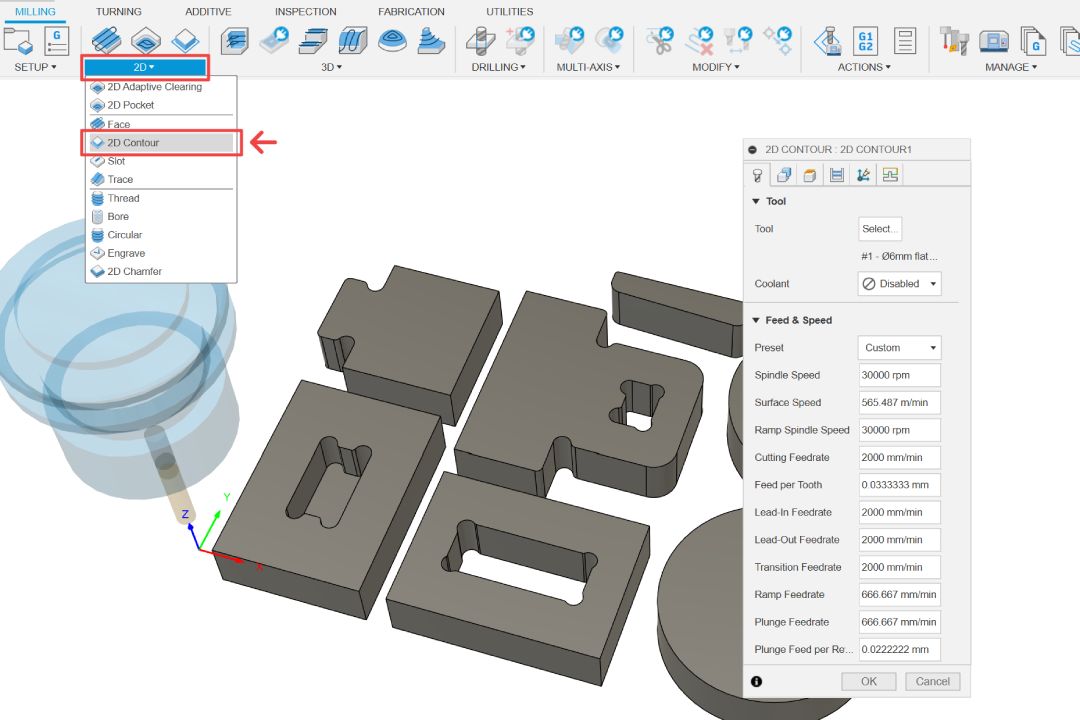
2D Pocket
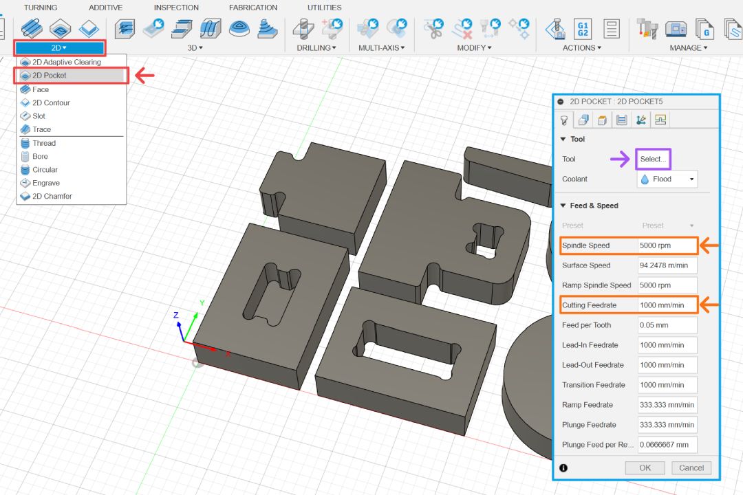
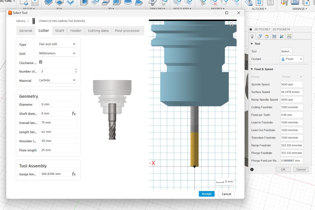
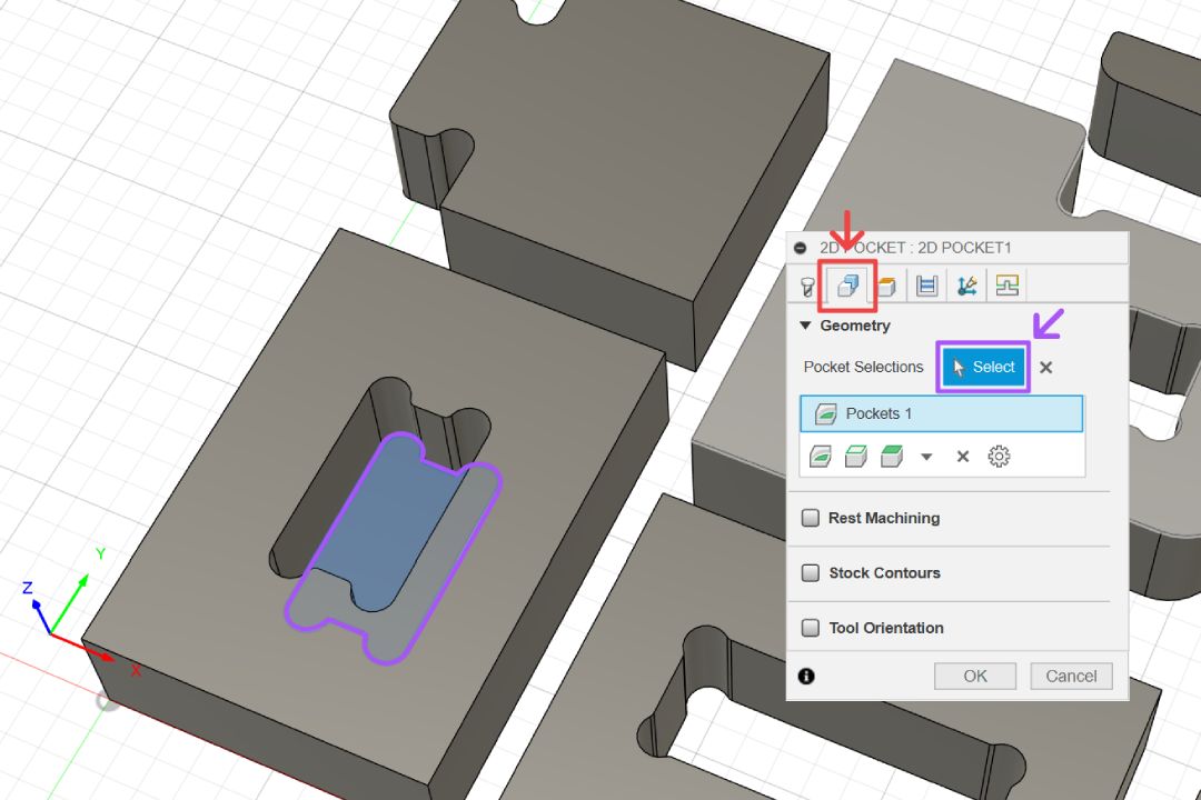
Just like the design workspace, Fusion groups the manufacturing tools together. Select 2D pocket under the 2D operations and a dialog box with multiple different tabs will pop up. The first thing you need to do is to select which tool are you going to use for this operation.
This will pop up the tool library which shows all the available tools came by default. If you can't find the bit there, you can create your own milling bit profile like shown below. The milling bit used for this project is 6 mm 2 flutes carbide flat end mill; it has total length of 75 mm, flute length of 25 mm, and 6 mm shaft diameter. Once you have selected the tool, you can also adjust the feed and speed on the dialog box.
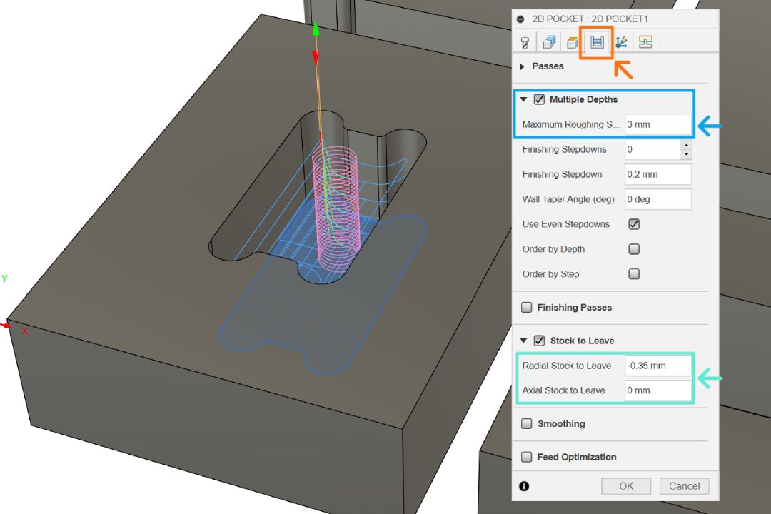
Go to geometry tab and select the face from blind mortise joint. The total depth of cut will be 15 mm so we will want to do the operation in multiple passes. Go to passes tab, activate the multiple depths option, and specify the stepdown value. It is recommended to use value maximum of half the diameter of the tool, in this case 3 mm. Larger value means the operation will be done faster because it needs to do less passes, but with a huge risk of breaking your tool bit.
We could also add X & Y axis tolerance in this operation by giving negative value for radial stock to leave. You will need to find the right value for yourself because it will differ for each combination of tool, machine, material, feed rate, speed, etc. You can add tolerance for z axis tolerance too with axial stock to leave, but all the blind mortise joints have been design with tolerance so we should just give 0 as the value.
Once you are done with setting the operation, the toolpath will be shown on top of the stock preview. You can also simulate the operation to see how long the operation will take, see if there is any potential issues that could arise from the operation, etc.
2D Contour
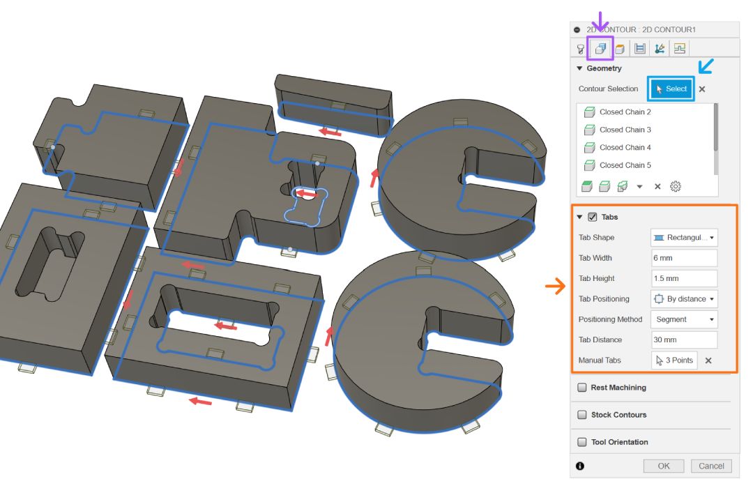
Next we setup a 2D contour operation. Repeat the same step to select the tool and depth passes, you can add tolerance too if necessary. Next, go to geometry tab and select all the edges of our models.
If you notice, the dialog box is largely identical compared to 2D pocket. In fact, all the operations have similar options with small difference when certain operation has specific feature only available to them. For example in 2D contour, there is an option to add tabs. This is useful to keep all your components in place while the machine is still operating.
The option settings are fairly self explanatory to use, you just need to tweak around the options till you find the settings what has adequate number of tabs. You can also add them manually when necessary.
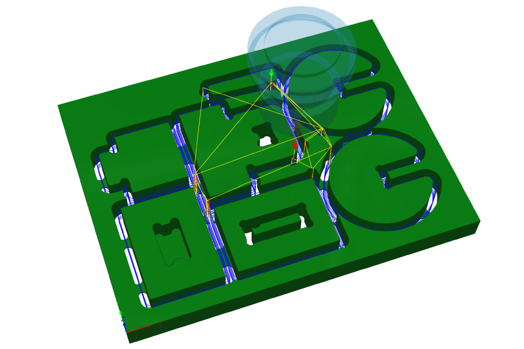
Once done, you will also see similar preview of the operation. As you notice, the previous operation results is also showing up here. This makes it really easy to fully visualize the entire operation and avoiding the risk of forgetting to mill some of the model's features.
You can also setup multiple different instance of the same operation if you need different settings. For example in this design, all the holes in the wedge joint also require a tolerance to be applied on radial stock to leave option.
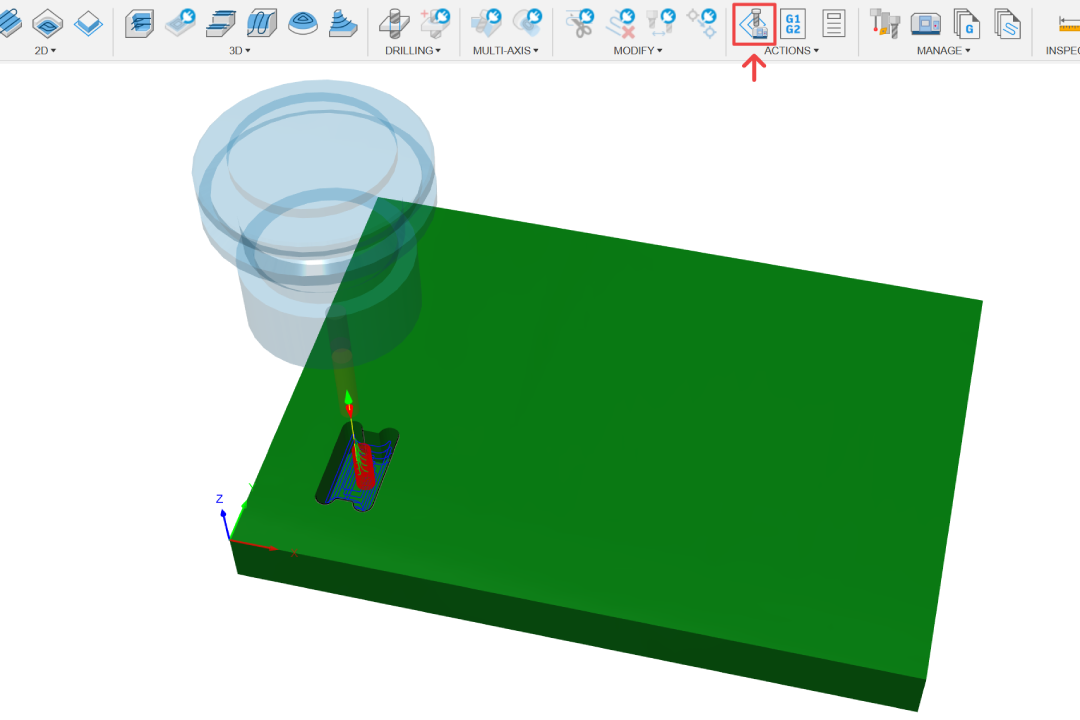
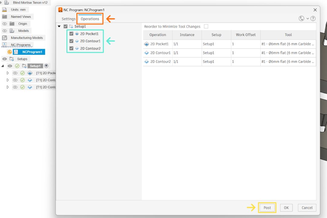
Generating Toolpaths
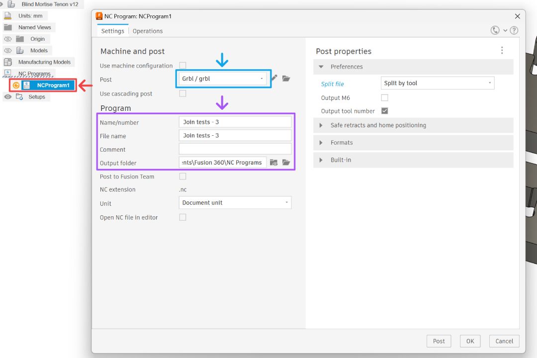
Now that the operations have been setup, we can generate the toolpaths. Double click the NCProgram and select post processor that your machine use. You can also specify the .nc file name and output folder here.
Next go to operations tab, select all the operations that you want to generates, then click post. After the .nc file is generated, we can use those files in our machine controller software like UGS (universal g-code sender), connect to your CNC machine, then fabricate your models.
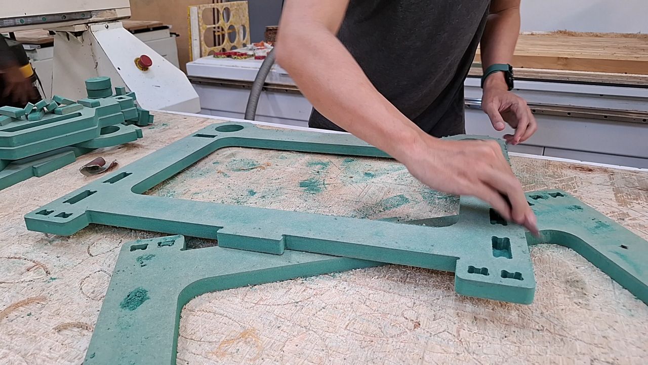
Fabrication and Assembly
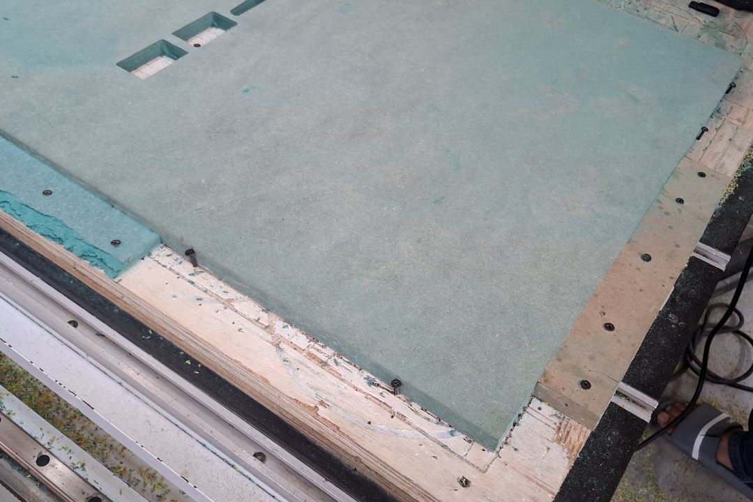
Place your material and mount them onto the working bed. There are many ways to mount them, but the simplest one would be to screw it down to a sacrificial board. Having a mounting reference like shown in the image below is also a good idea so we can mount different material to relatively same position very easily.
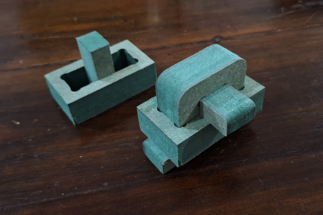
Next we can zero in our tool bit, then it's a good idea to do test cut and find the right feed, speed, and tolerance needed. It's almost impossible to have a comprehensive list of feed and speed because there are too much variables at play. They can only be found by testing to cut with those particular set of variables. The only measurement we can look for is if the cut produce a chip or dust. You will be producing some chips instead of just fine dust particles when you have dial in the correct settings.
The test shown here were using a tolerance of 0.35 mm, it produce a slight loose fit for the joinery which makes it ideal for ease of assembly. This design employs wedge joint and makes it possible to tighten up those loose fit joint while also makes it possible to disassemble it quickly. This tolerance can be applied as -0.35 mm value on radial stock to leave just like discussed on the previous CAM operation setup.

Once you find the right tolerance value, feed, and speed; then you can repeat the CAM steps for the entire designs using those said value. Generate the toolpaths then machine them with your CNC machine.
When the machining operations are finished, dismount your components, cut off any tabs if you use any, and deburr the edges by lightly sanding them. After than, you can proceed to assemble the components together.