Reflection
Finally we moved past making only LED blink! Honestly I think output device week should be longer because there are so many devices that I would like to learn how to program. I end up spending most of my time tinkering with OLED display because I designed my dev board to have an integrated display. Another reason is as a group, we have been preparing for the upcoming machine week and we want to build a machine with a control display.
Things That I Learned
Power Consumption
The group assignment continue to shed more light to things that I always wonder. This time about measuring energy consumption by our electronic. We did a simple power measurement on some servo motors. The first few test shows some obvious things like:
- The controller and the motor each has their own power consumption even when they are idle
- The motor draws more power when they are moving
- Bigger motor consumes more power
However, when we test few other scenarios, I learned something new that now it seems so obvious. The servo motor consumes more energy when they are put on load. Being able to peek into what our electronic using these measuring tools really give me new perspective.
5 V vs 3.3 V
My final project will most likely require me to use a relay because I need to toggle some 12 V devices and maybe a 220 V AC device. I understand the concept of how a relay works, so I thought it will be a walk in a park. Just need to connect the module to 5 V, GND, and a signal pin, then toggle the relay by setting that signal pin LOW or HIGH right? Guess what? It doesn't work! I thought maybe my module is broken so test with another one and alas it's not working neither.
Then it hit me, the relay module that I use is rated 5 V while the signal sent from my micro-controller is 3.3 V. This is when I understand that when we trigger digitalWrite(PIN, LOW) and digitalWrite(PIN, HIGH) on XIAO, it simply set that pin voltage to 0 V and 3.3 V respectively. There are relays that work with 3.3 V, but majority are designed for Arduino bigger boards which work at 5 V.
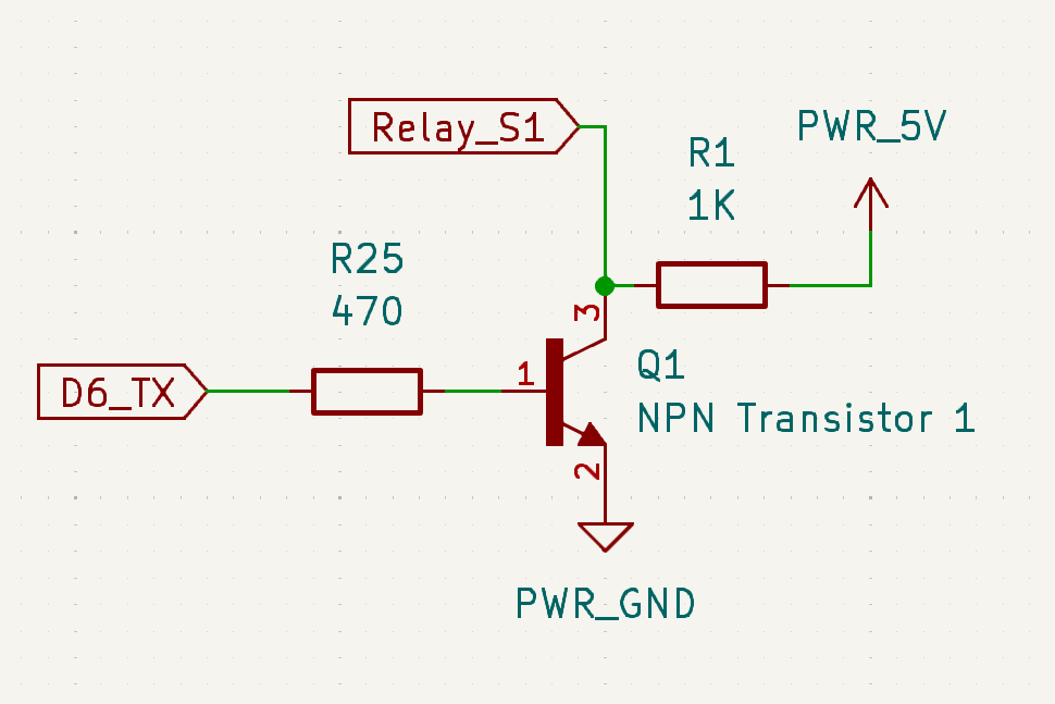
This lead me to look for a way to trigger a 5 V signal from a 3.3 V signal. Luckily there are multiple way to do so and one of them is to use a NPN transistor just like explained in this YouTube video by YoshiMaker. The image above shows the wiring diagram for the transistor and the video below shows a test comparing a circuit with and without a transistor.