Reflection
For our mechanical and machine design group assignment, we designed Cut-Craft, an automated semat cutter. Semat is a small bamboo sticks that is traditionally used for constructing canang, a Balinese daily offering that used to be made with all organic materials so it can be left composting in nature. Unfortunately nowadays for convenience, many people are resorting to use metal stapler for constructing it. Compared to using semat, stapler is much faster and easier to use, but it leave the metal contaminating the environment. We are trying to design a machine that might help people to replace the stapler back to semat by automating the cutting process.
Originally we were thinking to build an automatic wire stripping machine. Our thinking was it will be a simple and useful machine for the lab and we may be able to use it to cut semat. However, when we start assembling the mechanism, we realize it wasn't strong enough to strip or cut even a small cable! Luckily it is strong enough to cut semat, so we pivoted and committed to the semat cutter idea.
Task Division
In this assignment, we need to split the tasks between the three of us. Conveniently there are three major areas for this assignment: mechanism, actuation, and automation. Between the three of us, I have the most experiences in all of those areas, so I kind of took a project lead role and will help my colleagues wherever needed. Between Elaine and Tafia, Elaine is more experienced with programming and Tafia is more experienced with CAD modeling. With this in mind, I assigned Tafia to design the mechanism, Elaine to work on the actuation, and that leave me in charge for the automation.
Automation
For the automation, I programmed a simple control panel using a 0.96" OLED display and a rotary encoder. Below is a demo showing how the automation works on my development board.
Here are the basic function of this controller:
- Turn the knob to navigate through the menu
- Click one of the parameter to select them, then you can change the value using the knob
- Click again to set the value and exit back to the menu
- Once you have the correct settings, click the start button to start the operation. The button will change into a status showing how much cables (now semat) have been cut
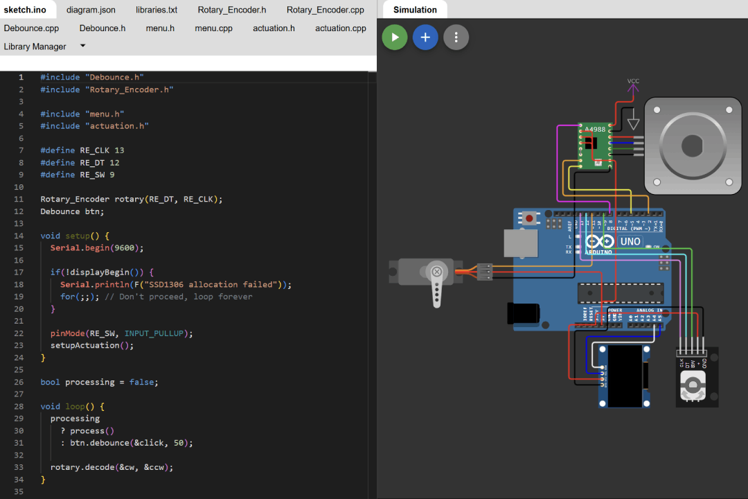
You could also check how this code in my Wokwi simulation. Note that for whatever reason, the parameter value did not show up when we run the simulation if I have more than 3 menu items.
Menu
I have explained in the details how to work with the display on my output device assignment, will do the same for the rotary encoder on my input device assignment, and for the menu user interface on interface and application programming assignment. However, this week I learned 2 very important thing in embedded programming, the first is how to separate our code into multiple files and the second one is millis.
As you see from some of my assignments, even a simple program could end up requiring quite a large number of codes. You could program every thing inside a single sketch, but the code will be unwieldy, hard to maintain or understand, and will be a nightmare to work collaboratively. The standard practice in any programming field is to compartmentalize your codes, for example even in basic web development you will split your code into multiple .html files, .css files, and .js files. In modern web development, the number of file could easily reach thousands of files if we count all the dependencies files.
You can watch this YouTube tutorial from Programming Electronics Academy to learn how to do this in Arduino IDE. In short summary, you'll need to create 2 new tab for each new separation, one for .cpp file and another for it's corresponding .h (header) file. With this in mind, I start to put all the codes that has to do with how to display my menu into it's own file.
/* menu.h */
#ifndef MENU_H
#define MENU_H
#include <Arduino.h>
#include <Wire.h>
#include <Adafruit_GFX.h>
#include <Adafruit_SSD1306.h>

extern Adafruit_SSD1306 display;
extern bool selected;
extern byte cursor;
extern byte values[];
extern const byte parameter_length;

bool displayBegin();
void displayUpdate();
void drawIndicators();
void drawParameters();
void drawButton();
void printCtr(const String &buf, int16_t x, int16_t y);
void printRg(const String &buf, int16_t x, int16_t y);

#endif

// -----------------------------------------------------------------------------------------------

/* menu.cpp */
#include "menu.h"

#define SCREEN_I2C_ADDR 0x3C // or 0x3C
#define SCREEN_WIDTH 128     // OLED display width, in pixels
#define SCREEN_HEIGHT 64     // OLED display height, in pixels
#define OLED_RST_PIN -1      // Reset pin (-1 if not available)

Adafruit_SSD1306 display(SCREEN_WIDTH, SCREEN_HEIGHT, &Wire, OLED_RST_PIN);

const byte parameter_length = 5;

const char *parameters[parameter_length] = {
  "AWG",
  "Length",
  "Lead 1",
  "Lead 2",
  "Qty"
};

byte values[parameter_length] = {
  20,
  15,
  5,
  5,
  10
};

byte cursor = 1;
bool selected = false;

bool displayBegin() {
  // SSD1306_SWITCHCAPVCC = generate display voltage from 3.3V internally
  bool initialized = display.begin(SSD1306_SWITCHCAPVCC, SCREEN_I2C_ADDR);

  if (initialized) {
    display.setRotation(1);
    displayUpdate();
  }

  return initialized;
}

void displayUpdate() {
  display.clearDisplay();
  display.setTextColor(SSD1306_WHITE);

  drawIndicators();
  drawParameters();
  drawButton();

  display.display();
}

// 'illustration', 64x9px
const unsigned char bm_wire [] PROGMEM = {
  0x00, 0x0f, 0xff, 0xff, 0xff, 0xff, 0xf0, 0x00, 0x00, 0x1f, 0xff, 0xff, 0xff, 0xff, 0xd8, 0x00,
  0x00, 0x3f, 0xff, 0xff, 0xff, 0xff, 0xb0, 0x00, 0x7f, 0xbf, 0xff, 0xff, 0xff, 0xff, 0xa7, 0xff,
  0xff, 0xbf, 0xff, 0xff, 0xff, 0xff, 0xaf, 0xff, 0xff, 0xbf, 0xff, 0xff, 0xff, 0xff, 0xa7, 0xfe,
  0x00, 0x3f, 0xff, 0xff, 0xff, 0xff, 0xb0, 0x00, 0x00, 0x18, 0x00, 0x00, 0x00, 0x00, 0xd8, 0x00,
  0x00, 0x0f, 0xff, 0xff, 0xff, 0xff, 0xf0, 0x00
};
// 'lead-indicator', 11x3px
const unsigned char bm_lead [] PROGMEM = {
  0x80, 0x20, 0xaa, 0xa0, 0x80, 0x20
};
// 'length-indicator', 44x3px
const unsigned char bm_length [] PROGMEM = {
  0x80, 0x00, 0x00, 0x00, 0x00, 0x10, 0xaa, 0xaa, 0xaa, 0xaa, 0xaa, 0xb0, 0x80, 0x00, 0x00, 0x00,
  0x00, 0x10
};

void drawIndicators() {
  display.drawBitmap(0, 11, bm_wire, display.width(), 9, 1);

  if (cursor == 1) {
    display.drawBitmap(10, 23, bm_length, 44, 3, 1);
    printCtr("mm", 0, 26);
  }

  if (cursor == 2)
    display.drawBitmap(0, 23, bm_lead, 11, 3, 1);

  if (cursor == 3)
    display.drawBitmap(53, 23, bm_lead, 11, 3, 1);
}

#define OFFSET 29

void drawParameters() {
  for (int i = 0; i < parameter_length; i++) {
    int y = OFFSET + (i * 16);

    if (cursor == i) {
      if (selected) {
        display.fillRoundRect(0, y, display.width(), 15, 3, SSD1306_WHITE);
        display.setTextColor(SSD1306_BLACK);
      } else {
        display.drawRoundRect(0, y, display.width(), 15, 3, SSD1306_WHITE);
      }
    }

    display.setCursor(3, y + 4);
    display.print(parameters[i]);
    printRg(String(values[i]), 3, y + 4);

    if (selected)
      display.setTextColor(SSD1306_WHITE);
  }
}

extern bool processing;
extern unsigned int qty;

void drawButton() {
  display.fillRoundRect(0, 113, display.width(), 15, 3, SSD1306_WHITE);

  if (cursor == parameter_length)
    display.drawRoundRect(1, 114, display.width() - 2, 13, 3, SSD1306_BLACK);

  display.setTextColor(SSD1306_BLACK);

  if (processing) {
    String processed = String(values[4] - qty) + "/" + String(values[4]);
    printCtr(processed, 0, 117);
  } else {
    printCtr("Start", 0, 117);
  }

  display.setTextColor(SSD1306_WHITE);
}

void printCtr(const String &buf, int16_t x, int16_t y) {
  int16_t x1, y1;
  uint16_t w, h;
  display.getTextBounds(buf, x, y, &x1, &y1, &w, &h); //calc width of new string
  display.setCursor((x + (display.width() - w) / 2), y);
  display.print(buf);
}

void printRg(const String &buf, int16_t x, int16_t y) {
  int16_t x1, y1;
  uint16_t w, h;
  display.getTextBounds(buf, x, y, &x1, &y1, &w, &h); //calc width of new string
  display.setCursor((display.width() - x - w), y);
  display.print(buf);
}
Debounce
So far we only have ever use delay to time something in our code. This might suffice for simple program that only need to do one thing at a time. When you execute delay, your controller stop working for the specified amount of time before continuing to the next line of code. This means your inputs will stop working on those period too, you can't update your display, etc.
To work around this, you could use millis and kind of simulate a multitasking operation. Learn more in depth about it from this YouTube tutorial from the same channel. Because I think this pattern will be used a lot, I decided to abstract this into it's own file, essentially writing my very own first library.
/* Debounce.h */
#ifndef DEBOUNCE_H
#define DEBOUNCE_H
#include <Arduino.h>
#include <functional>

class Debounce {
  public:
    void debounce(std::function<void()> callback, unsigned long time);
    void reset();
  private:
    unsigned long lastBounce = 0;
};

#endif

// -----------------------------------------------------------------------------------------------

/* Debounce.cpp */
#include "Debounce.h"

void Debounce::debounce(std::function<void()> callback, unsigned long time) {
  unsigned long now = millis();

  if ((now - lastBounce) < time)
    return;

  lastBounce = now;
  callback();
}

void Debounce::reset() {
  lastBounce = millis();
}
Actuation
Next, I utilize the debounce code to create a sequencing functionality and adjust the actuation codes from Elaine to use this sequencer instead of delay. Beside that, I use the variable for the actuation using variable from our menu and add displayUpdate at the end of the sequence to update the status shown on the screen.
/* actuation.h */
#ifndef ACTUATION_H
#define ACTUATION_H
#include <Arduino.h>
#include <AccelStepper.h>
#include <Servo.h>
#include <Debounce.h>

void setupActuation();
void process();

void sequencer();
void initSequence();
void pull();
void servoDown();
void servoUp();
void resetSequence();

#endif

// -----------------------------------------------------------------------------------------------

/* actuation.cpp */
#include "menu.h"
#include "actuation.h"

#define ST_STEP 2
#define ST_DIR 5
#define ST_EN 8

#define MICROSTEP 16

AccelStepper stepper(1, ST_STEP, ST_DIR);

#define SV_SG 11

Servo servo;

void setupActuation() {
  stepper.setMaxSpeed(4000);
  stepper.setAcceleration(2500);
  stepper.setCurrentPosition(0);

  pinMode(ST_EN, OUTPUT);
  digitalWrite(ST_EN, LOW);

  servo.attach(SV_SG);
}

extern unsigned int qty;
extern unsigned int length;
unsigned int steps;

Debounce sequence;

byte sequenceCursor = 0;
const byte sequence_length = 3;
void (*sequences[sequence_length])() = { pull, servoDown, servoUp };
unsigned long durations[sequence_length] = { 1500, 500, 500 };
bool sequence_triggered[sequence_length] = { false, false, false };

bool sequenceInitialized = false;

void process() {
  initSequence();

  (*sequences[sequenceCursor])();

  if (!sequence_triggered[sequenceCursor])
    sequence_triggered[sequenceCursor] = true;

  sequence.debounce(&sequencer, durations[sequenceCursor]);
}

void initSequence() {
  if (sequenceInitialized)
    return;

  sequence.reset();
  sequenceInitialized = true;
  steps = length * 4 * MICROSTEP;
  durations[0] = sqrt(length)*275 + 500;
}

void sequencer() {
  sequenceCursor++;

  if (sequenceCursor >= sequence_length)
    resetSequence();
}

unsigned int pos = 0;

void pull() {
  if (!sequence_triggered[0])
    stepper.moveTo(steps);

  if (stepper.distanceToGo() != 0)
    stepper.run();
}

void servoDown() {
  if (sequence_triggered[1])
    return;

  servo.write(180);
}

void servoUp() {
  if (sequence_triggered[2])
    return;

  servo.write(90);
}

extern bool processing;

void resetSequence() {
  for (int i = 0; i < sequence_length; i++)
    sequence_triggered[i] = false;

  sequenceCursor = 0;
  stepper.setCurrentPosition(0);

  qty--;

  if (qty == 0) {
    processing = false;
    sequenceInitialized = false;
  }

  displayUpdate();
}
Main Sketch
The last bit is to connect all those files inside the main sketch. We will need to include those files just like how we include a library, then trigger any functions needed inside setup and loop function. I put the rotary encoder logic here to control the menu and the actuation, but I could also separate it to another file if necessary.
/* cut_craft.ino */
#include <Debounce.h>
#include <Rotary_Encoder.h>

#include "menu.h"
#include "actuation.h"

#define RE_CLK D3
#define RE_DT D0
#define RE_SW D2

Rotary_Encoder rotary(RE_DT, RE_CLK);
Debounce btn;

void setup() {
  Serial.begin(9600);

  if(!displayBegin()) {
    Serial.println(F("SSD1306 allocation failed"));
    for(;;); // Don't proceed, loop forever
  }

  pinMode(RE_SW, INPUT_PULLUP);
  setupActuation();
}

bool processing = false;

void loop() {
  if (processing)
    return process();

  btn.debounce(&click, 50);
  rotary.decode(&cw, &ccw);
}

bool clicked = false;
unsigned int length;
unsigned int qty;

void click() {
  if (digitalRead(RE_SW) == LOW && !clicked) {
    clicked = true;

    if (cursor < parameter_length) {
      selected = !selected;
    } else {
      processing = !processing;
      length = values[1];
      qty = values[4];
    }

    displayUpdate();
  } else if (digitalRead(RE_SW) == HIGH && clicked) {
    clicked = false;
  }
}

void cw() {
  if (!selected && cursor == parameter_length)
    return;

  if (selected) {
    if (cursor == 1) {
      if (values[1] < 100) {
        values[1]++;
      }
    } else if (values[cursor] < 255) {
      values[cursor]++;
    }
  } else {
    cursor++;
  }

  displayUpdate();
}

void ccw() {
  if (!selected && cursor == 1)
    return;

  if (selected) {
    if (cursor == 1) {
      if (values[1] > 5) {
        values[1]--;
      }
    } else if (cursor == 4) {
      if (values[4] > 1) {
        values[4]--;
      }
    } else if (values[cursor] > 0) {
      values[cursor]--;
    }
  } else {
    cursor--;
  }

  displayUpdate();
}
Other Contributions
Other than working on the automation, I also contribute in some other aspects of the machine. Below is a breakdown of other things that I did this week:
Conception
By evaluating skill level of the three of us, I thought that we should build a machine that is rather simple. However, I don't really like the idea of making a machine that don't serve any purpose which leads me to propose building a wire stripping machines.
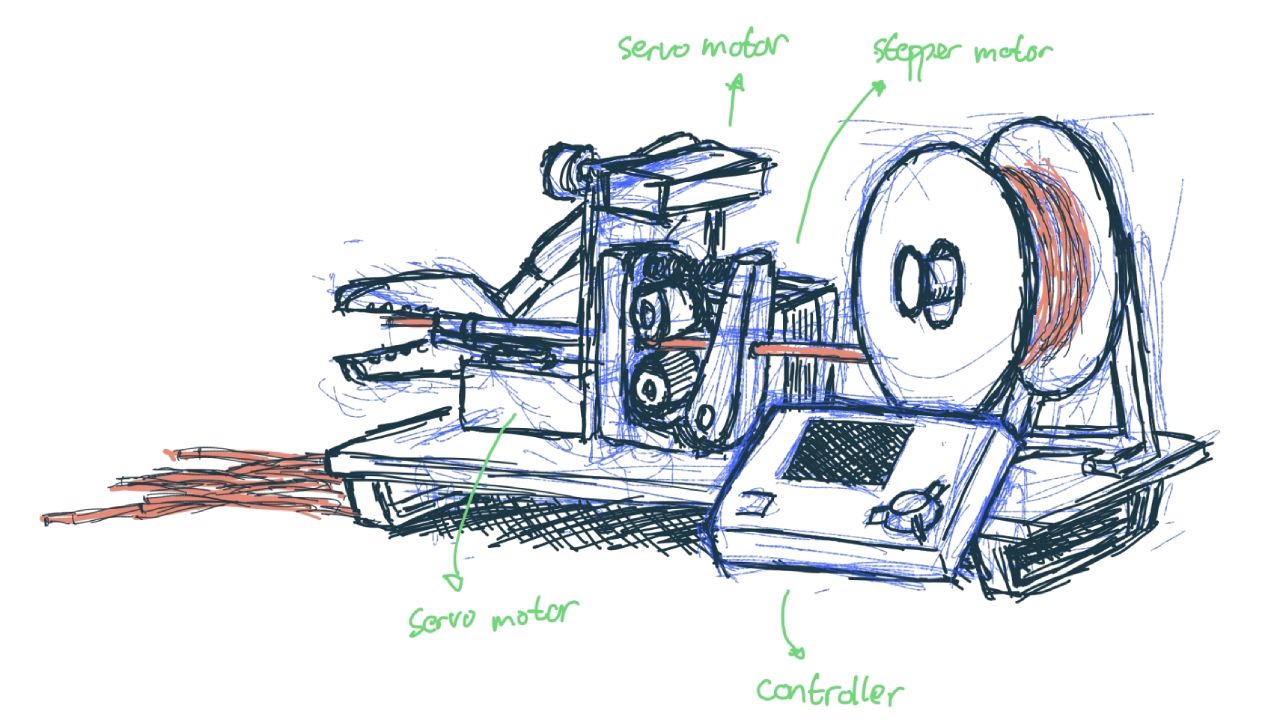
There are many examples of similar machines on YouTube, each have their own unique way to work, but all follow the same basic principle. It has a controller that trigger a stepper motor to feed the wire, then trigger another stepper motor or servo motor to move a cutting or stripping mechanism. After analyzing those machines, I made a rough sketch to got a feel how the machine will look, what components are required, where they will be placed, what sort of mechanism need to be fabricated, etc.
Low-Fi Prototyping
Although Tafia is fairly proficient in CAD modeling, she never design a mechanism before. She is a little bit confused where to start so I gave a suggestion to build a low fidelity prototype first. Below is the prototype we made out of cardboard, tape, and hot glue gun. Eventually I also attached the electronics to it too for initial actuation testing too.
Wiring The Electronics
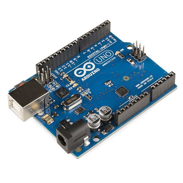
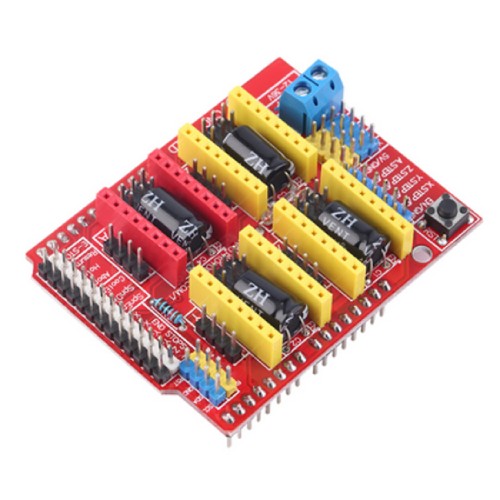
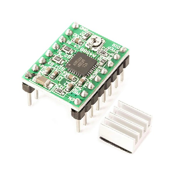
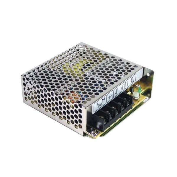
This week we are allowed to use commercial boards so we decided use Arduino UNO, CNC shield V3, and A4988 driver to simplify our wiring even though we only use 1 nema 17 stepper motor. The motor will be powered through the CNC shield by a 12 V power supply.
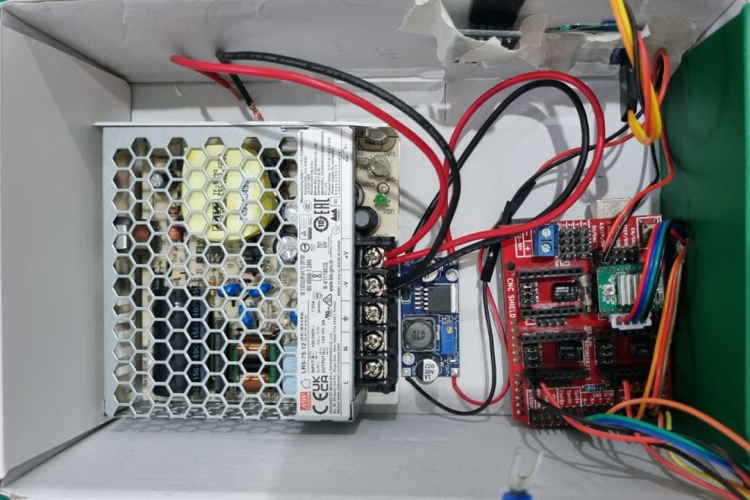
Initially I though the CNC shield will also power the Arduino UNO, to my surprise they don't! The Arduino still need to be powered by an external power source, for example if we connect it to our computer using a USB cable. This make sense if you are using your computer to control a CNC machine, but our machine will work as a standalone machine. Attaching battery would be an even ridiculous solution, there got to be a way to just use the power supply for Arduino.
Well, Arduino has a Vin pin exactly for this scenario. However, for whatever reason, the CNC shield did not expose this pin! After reading through some forums, there is actually another easy way to do this, although not many people document it nor recommend it. It's because this method could easily fried your board if you made simple wiring mistake. In fact there are multitude of ways you could fried your micro-controller, this YouTube video from the same channel summarize nicely all the things to avoid.
Proceed with caution! You will need to use a DC buck converter, connect the input voltage to your 12 V power supply, and step down the output to 5 V. Next, connect the output to 5 V and GND pin on the CNC shield and I connect the 5 V line through a diode just to be safe.
Mechanical Assembly, Tweaking, and Refinements
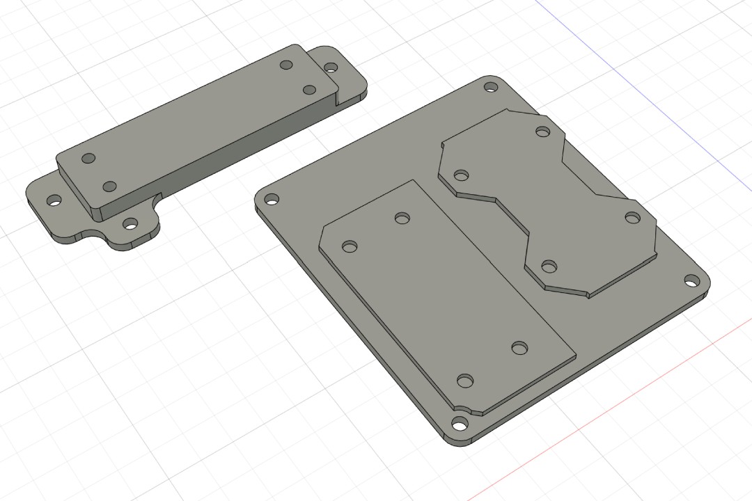
The last step was to assemble the machine together. To save time, I'm using aluminum extrusions as a base, which actually a base I had from making a Recreator3D Ender 3. Because Tafia was away due to Eid Mubarak, I designed the base plates to hold all the mechanism. They are simple flat 3D printed parts with some mounting holes.
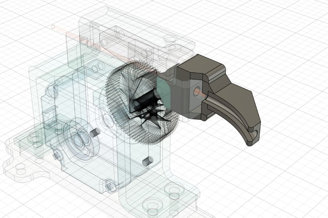
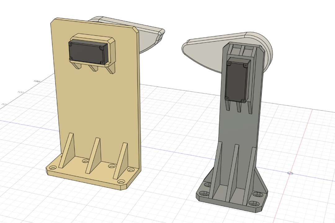
The plier holder works quite well, but I feel like the servo bracket could be made sturdier. The orientation of the servo motor also make the component Tafia designed unnecessarily wide in my opinion. So I decided to adjust the design a little bit as shown below.
While assembling and testing the cam lever mechanism, we realize that the servo is not powerful enough to drive the plier. This leads us to improvise a little bit, starting by changing the lever orientation, removing the plier's spring, to the hilarious rubber band experiment! This is the point where we pivoted from making a wire cutter into a semat cutter.
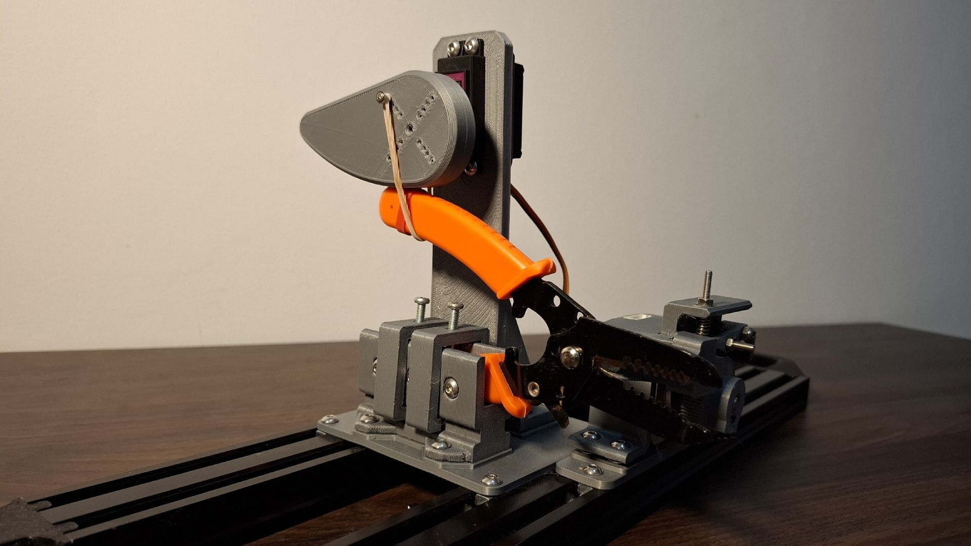
One last issue we ran into is the position of the semat after being fed to the plier was not aligned with the blade part. To fix this, I designed a simple model to guide the semat when it is being fed. This turns out into a good idea because it put the semat on an angle relative to the plier and making the cut result to have a pointy end that is ideal to use for making canang.