Intro to Embedded Programming
Whenever you do programming, you can only be 100% sure if everything works when you upload your code to the intended environment. For web, that means you upload it to a server and are able to access it through a web browser; for mobile apps, you compile it and install it on your mobile device; and for embedded programming, you compile it and upload it to the microcontroller of your choosing.
However, the programming process is never linear. You will always write code, test it out, troubleshoot any issues or errors, and then repeat until you achieve the intended functionality. It is guaranteed that you will run into errors, whether it's a typo, missing dependencies, missing semicolon, etc. It would be very inefficient if we needed to compile and upload our code for every single little change we make while still in the development phase.
In web development, we can set up a localhost environment where you can simulate a server and access it through your browser. This enables the process of writing and testing your code rapidly. Luckily, there are platforms that can help simulate uploading embedded programming into a microcontroller, such as Tinkercad Circuit and Wokwi. We will use the latter because it provides more microcontroller architectures to simulate.
In embedded programming, an issue could result not only from the code, but from many other factors. It could be a wiring issue, a soldering issue, a dead component, a bad power supply, etc. Having a way to verify that the code works first before uploading is a tremendous help in eliminating guesswork. You can watch this short introduction to learn more about Wokwi and how to use it.
Hello World of Embedded Programming
In every programming language, there is a Hello World project that people use to learn how to code. In embedded programming, it is to code a blinking LED light. We are going to use Quentorres board, but unfortunately it won't be available in Wokwi, and even the XIAO RP2040 which is used on Quentorres is not available. We have to use Pi Pico because it has the same RP2040 microcontroller, then try to reverse engineer the Quentorres inside Wokwi.
Wokwi Reconstruction
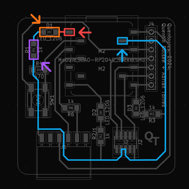
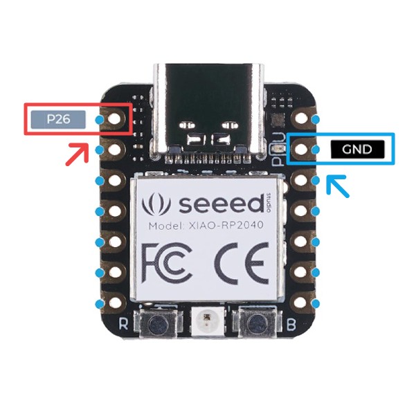
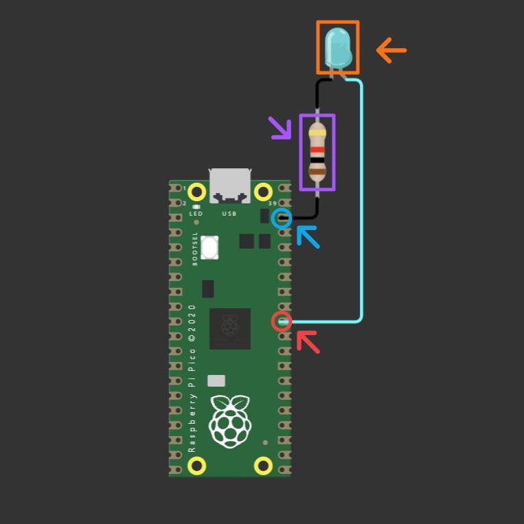
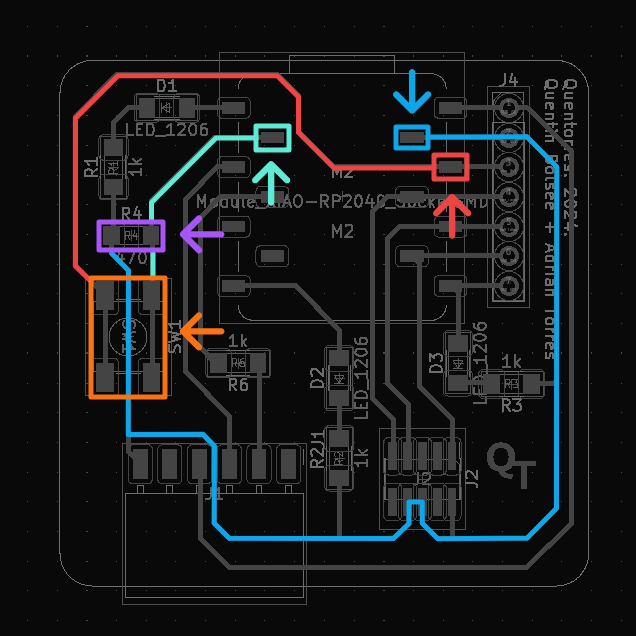
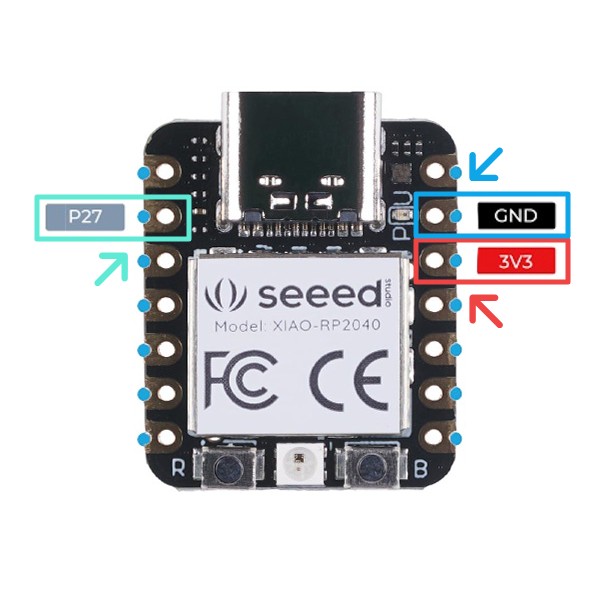
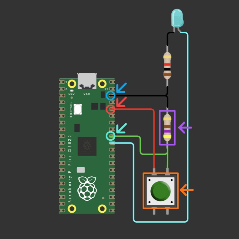
First, we need to identify the LED wiring on Quentorres shown in figure 1 while crosschecking the XIAO RP2040 pinout shown in figure 2. The LED anode is connected to pin 26, then on the cathode it is connected to a 1K Ω resistor which is connected to the ground (GND). Then we can reconstruct this circuit in Wokwi just like shown in figure 3.
Basic Blink
For the code, we can copy it from this Arduino repository. We need to define our own constant variable led_pin with a value of 26 (our pin number), then replace LED_BUILTIN with it.
#define led_pin 26

// pinMode(LED_BUILTIN, OUTPUT);
pinMode(led_pin, OUTPUT);

// digitalWrite(LED_BUILTIN, ...);
digitalWrite(led_pin, ...);
Press the play button on the top middle of the screen to start the simulation. It will take some time when you first compile it or whenever you make changes to your code. If there are no issues with your code, you can see your simulation just like shown in the video below.
Input, Output, and Communication
Now that we have a blinking LED, we have successfully worked with an output device. Next, we will learn how to work with an input and communicate through the serial port. For the input, we can work with Quentorres' button.
Wokwi Reconstruction
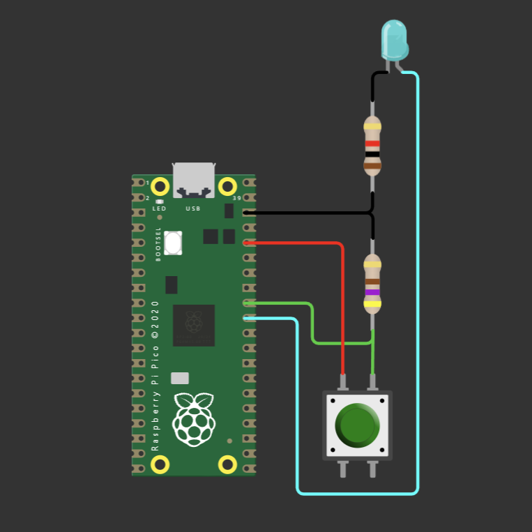
We can see the button circuit highlighted in figure 4 and crosscheck the pinout with figure 5. The button is connected with pin 27 on one end and connected with 3V3 power on the other. A 490 Ω resistor is connected between the button and the pin, then the other end of the resistor is connected to the ground (GND). The reconstruction of this circuit on top of the previous circuit in Wokwi can be seen in Figure 6.
Button Blink
For the code, we will be using the RP2040 button blink example provided by Prof. Neil Gershenfeld. We will need to change the led_pin to 26 and button_pin to 27.
#define led_pin 26
#define button_pin 27
Troubleshooting: Serial Communication
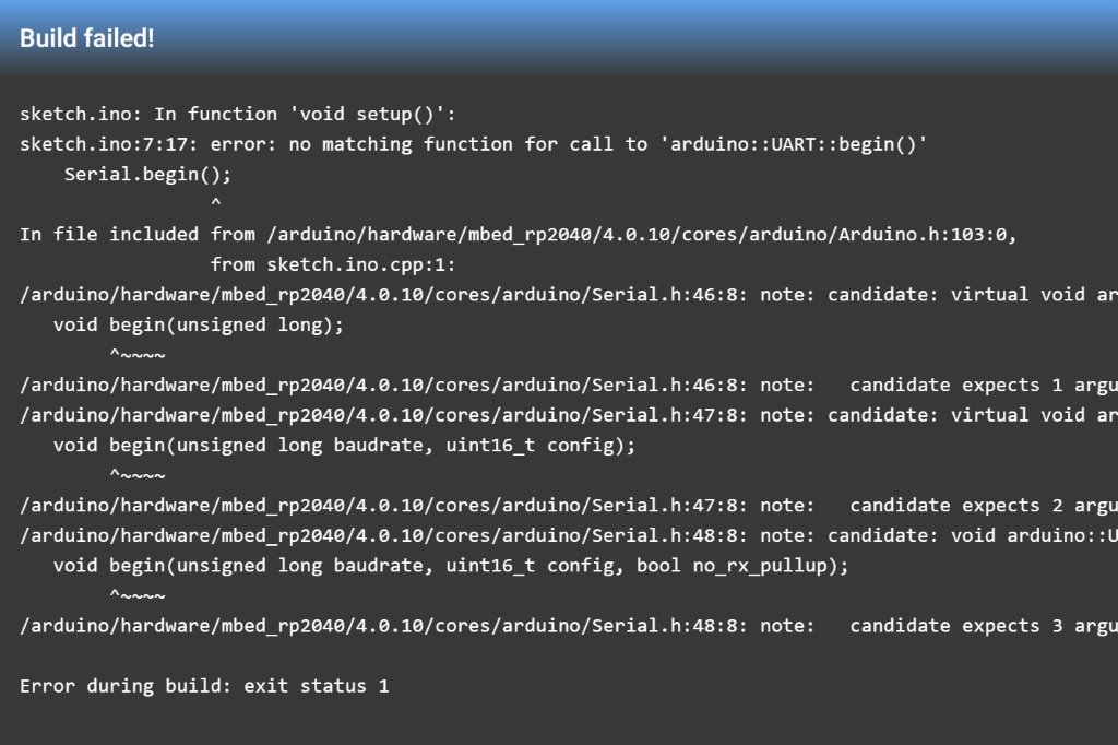
If you follow these instructions to the letter, you will run into an error when you try to simulate the code now. This is the perfect example of a code that works correctly in one environment but might fail in another. You will be shown a stack trace similar to the one shown in figure 7, and you can see which line of code caused it. A little inspection of other Wokwi projects that use Pi Pico, such as the Pico starter template, shows that we need to use Serial1 instead of Serial, and we need to specify the baud rate.
// Serial.begin();
Serial1.begin(115200);

// Check the number of bytes available for reading from serial port
if (Serial1.available()) {
    ...
    // Read serial data as string
    String s = Serial1.readString();
    ...
}
Now, if you run the simulation again, you can see the error is gone, just like in the video below. The Serial1.println(...) function works, and the code inside the Serial1.available() conditional works as intended. However, the button is still not working.
Troubleshooting: Button
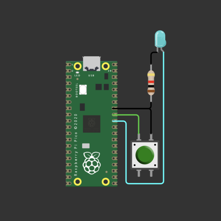
Similarly to how we troubleshooted the serial error, we can inspect other projects that use a button, such as the Pico mini piano. Interestingly, its button circuit is different from the one we have. The button is connected to a pin on one end and ground on the other. Figure 9 shows how the circuit will look like if we wired it similarly to the piano example.
After the circuit changed, the simulation actually works as intended. Unfortunately, we can't change the layout for Quentorres, so we will have to figure out the cause of the issue. That's when we were first introduced to the concept of a pull-up button, which is how our code and the piano example configure the button. You can learn more by watching these YouTube tutorials: Pull-up resistor or Pull-up vs Pull-down.
For the code to work on the Quentorres setup, we must change the button pinMode from INPUT_PULLUP to INPUT. This will also reverse the expected output of digitalRead of the pin, so we will have to toggle the values inside our if statement from LOW to HIGH and vice versa.
// pinMode(button_pin, INPUT_PULLUP);
pinMode(button_pin, INPUT);

// if ((digitalRead(button_pin) == LOW) && button_up) {
if ((digitalRead(button_pin) == HIGH) && button_up) {
    ...
// } else if ((digitalRead(button_pin) == HIGH) && !button_up) {
} else if ((digitalRead(button_pin) == LOW) && !button_up) {
    ...
}
If you start the simulation now, you can see that all the code is working as expected. Time to upload it to your actual board.
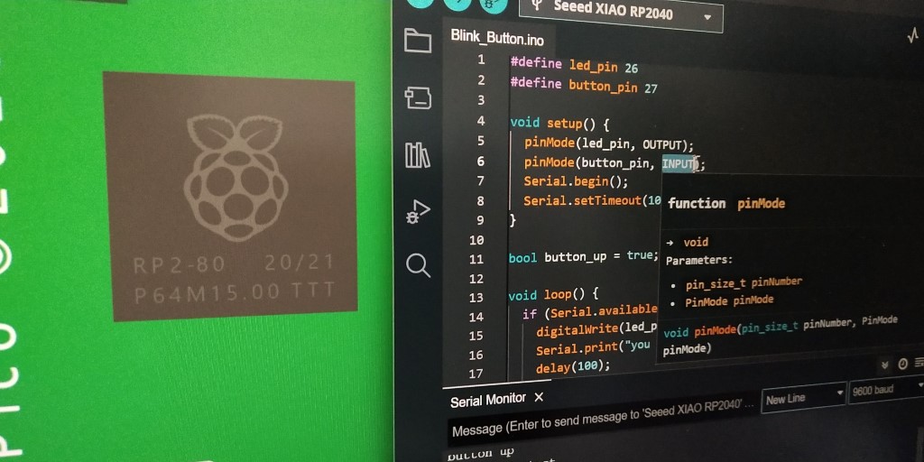
Uploading to Quentorres
Copy and paste the code from Wokwi to your Arduino IDE. Remember to change Serial1 back to Serial, and with a little bit of refactoring, your code should look similar to what is shown below.
#define led_pin 26
#define button_pin 27

void setup() {
    pinMode(led_pin, OUTPUT);
    pinMode(button_pin, INPUT);
    Serial.begin();
    Serial.setTimeout(10);
}

bool button_up = true;

void loop() {
    if (Serial.available()) {
        digitalWrite(led_pin, HIGH);
        Serial.print("you typed: " + Serial.readString());
        delay(100);
        digitalWrite(led_pin, LOW);
    }

    if ((digitalRead(button_pin) == HIGH) && button_up) {
        digitalWrite(led_pin, HIGH);
        Serial.println("button down");
        button_up = false;
    }
    else if ((digitalRead(button_pin) == LOW) && !button_up) {
        digitalWrite(led_pin, LOW);
        Serial.println("button up");
        button_up = true;
    }
}
Connect your Quentorres and make sure the IDE selects Seeed XIAO RP2040 for the board and the correct COM port. If you want to verify the code first, you can press the verify button now. If not, click the upload button to flash your code to your Quentorres. Once uploaded, verify the functionality for both the button and the serial communication.