Parametric Icosahedron Construction Kit
The icosahedron is a three-dimensional geometry with 20 faces. The most well-known type is the regular icosahedron, which consists of 20 equilateral triangle faces, 30 edges, and 12 vertices. For this assignment, I am creating a parametric icosahedron construction kit that has two components: a segment similar to the edges, and a connector to join the segments, akin to the vertices.
Creating Icosahedron
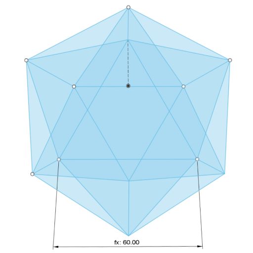
First, let's construct the geometry as a guide. Fusion 360 doesn't have a tool to generate an icosahedron geometry out of the box. Follow this tutorial to create one using 3D sketches and mostly equal constraints.
Defining Parameters
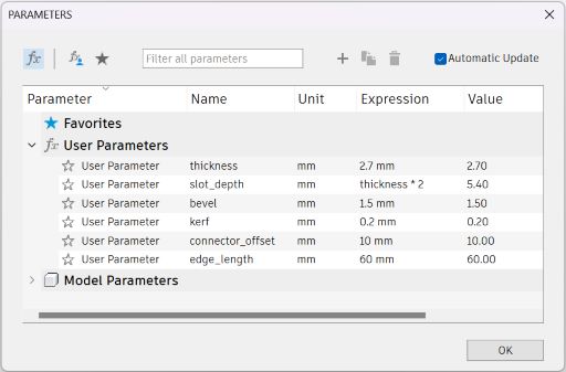
Next, let's define our parameters. As you can see above and below, I've set the edge_length to 60 mm. I'll be using cardboard with a thickness of 2.7 mm and a kerf value of 0.2 mm. The slot_depth is determined by the thickness, ensuring adaptability if we change to a different material. Other values I've defined include connector_offset to set the connector plane position, and the bevel value to be applied to all the slots and edges.
Modeling
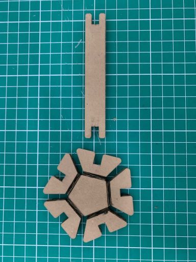
Connector
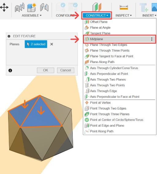
Before creating the components, let's establish a drawing plane that we will utilize for both components. We require a plane that aligns with one of the edges. One straightforward method to create it is by generating a MidPlane between two faces positioned side by side.
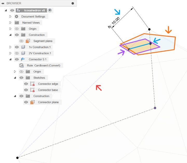
Since we are going to assemble components, let's start by creating a New Component, name it Connector, then follow these steps:
- Create Sketch on the newly created plane and project the geometry edge onto it.
- Add a horizontal Line, using
connector_offsetas the Sketch Dimension from the vertex, then Finish Sketch. - Utilize that horizontal line to construct a plane using Plane at Angle.
- Create Sketch on that plane. Use the Polygon tool to create a pentagon. Apply a Coincident constraint to the center point to the axis and set one of the edges to MidPoint with respect to the geometry edge.
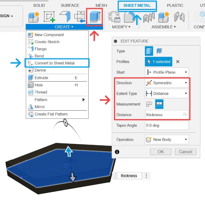
Next, let's Extrude the pentagon. Set the direction to Symmetric, the measurement to Whole Length, and the distance to thickness. To create the flanges, we need to convert the component into a sheet metal component. Ensure you are inside Sheet Metal workspace, then navigate to Create → Convert to Sheet Metal.
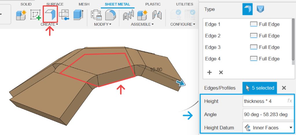
Once converted, we can utilize the Flange tool. Select the five edges, and drag them downward. In the dialog box, adjust the values as follows:
- Height:
thickness * 4 - Angle:
90 - 58.283 - Height Datum:
Inner Faces
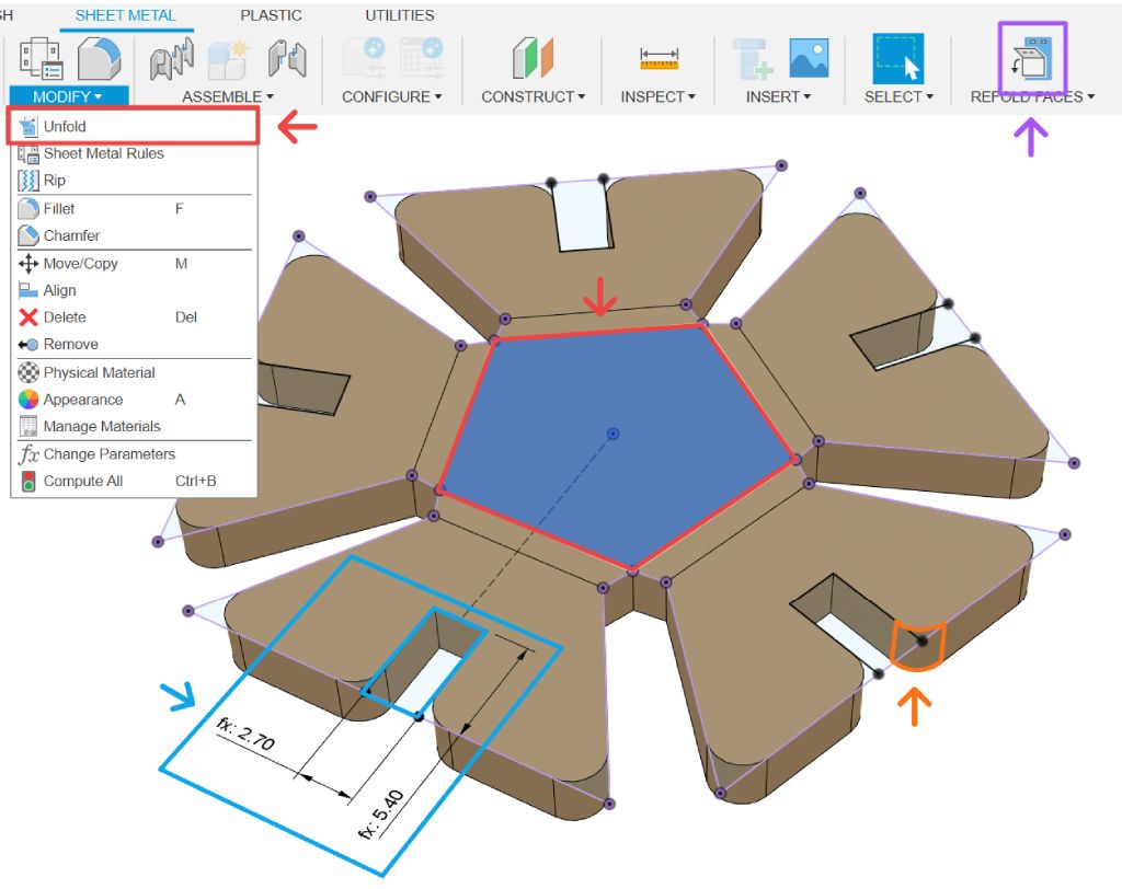
Follow the steps below to add slots and finalize the connector:
- First, we need to Unfold the body; select the pentagon as the stationary face.
- Create Sketch referencing the body; construct a Rectangle touching the edge in the middle; apply
slot_depthandthickness - kerfas values; duplicate it using Circular Pattern; and Extrude it downward with a Cut operation. - Apply a Fillet to all the flange and slot edges using
bevelas the value. - Refold the body, and you are finished with this component.
Segment
Create a New Component and name it Segment. Then, using the first plane, Create Sketch. Design the segment profile with the edges offsetted by connector_offset. Add the slot on both ends with dimensions of slot_depth and thickness - kerf.
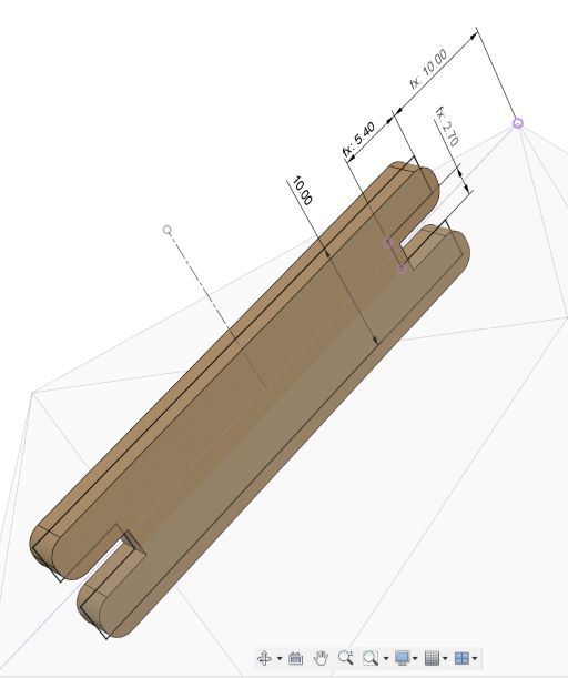
Extrude the profile by thickness, then Fillet the edges by bevel, and you have finished with this component.
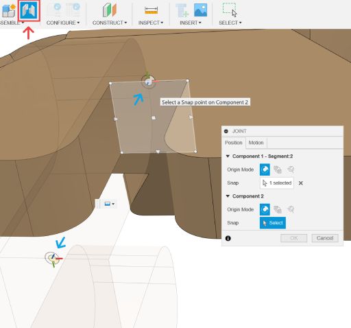
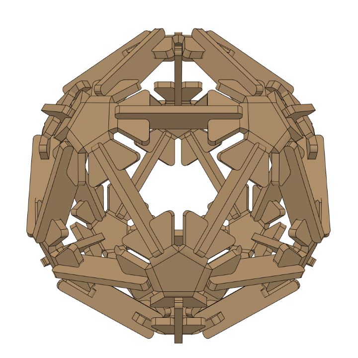
Assembly
To visualize the fully assembled kit inside Fusion 360, let's first create a New Component. Then, copy and paste the Connector and Segment components inside it. After that, you'll want to Joint them together by selecting the aligned snap points from both components.
Next, you can Duplicate With Joints the segment and select the corresponding snap points on the connector.
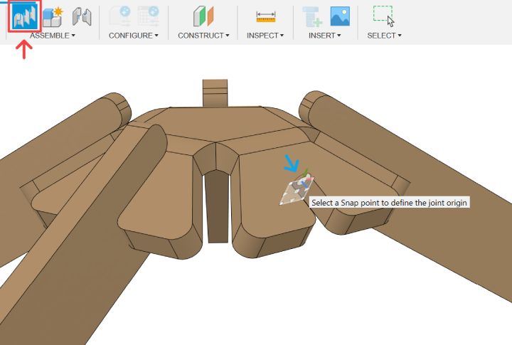
Repeat the steps with connectors until you have fully assembled an icosahedron geometry. The composition of your components will consist of 12 connectors and 30 segments.
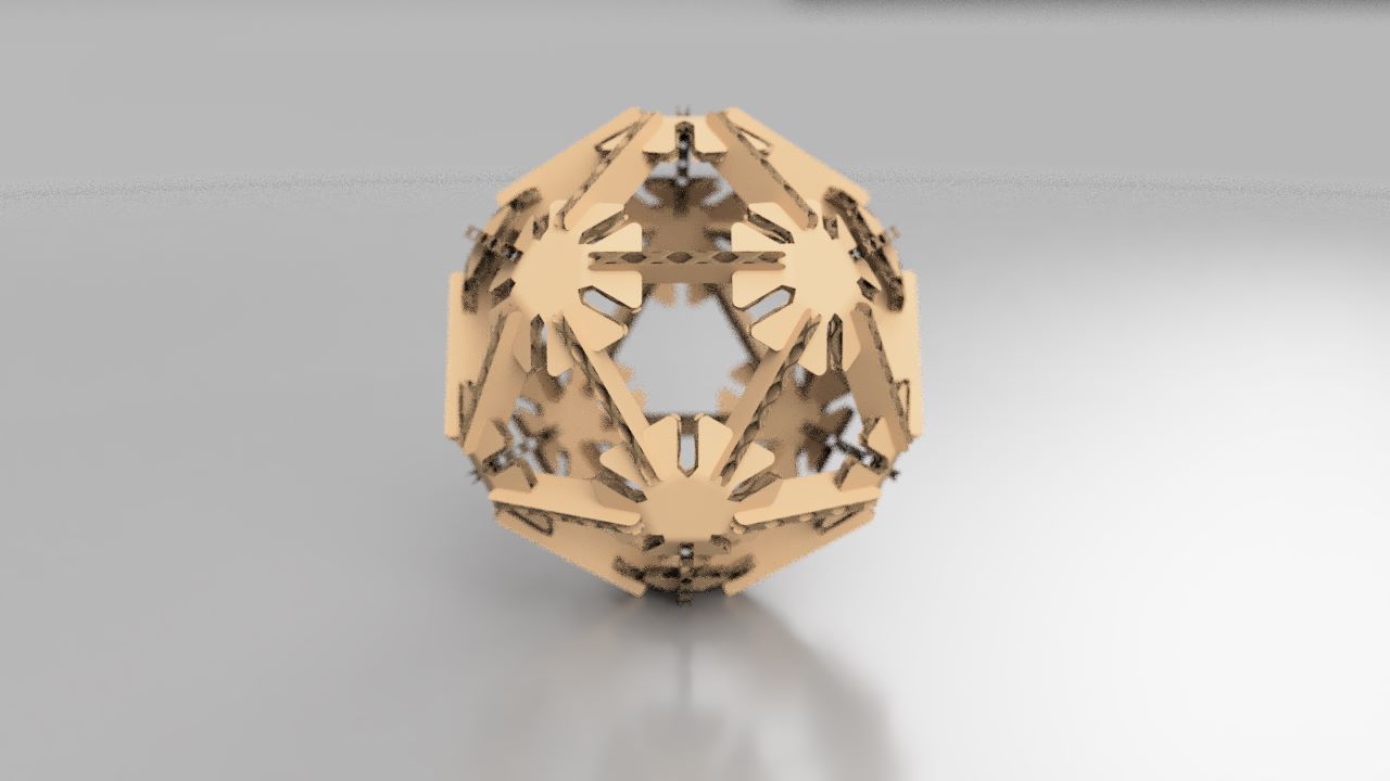
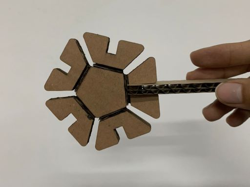
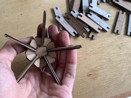
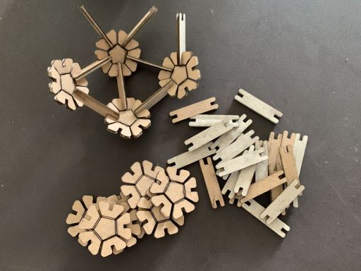
Laser Cutting Results
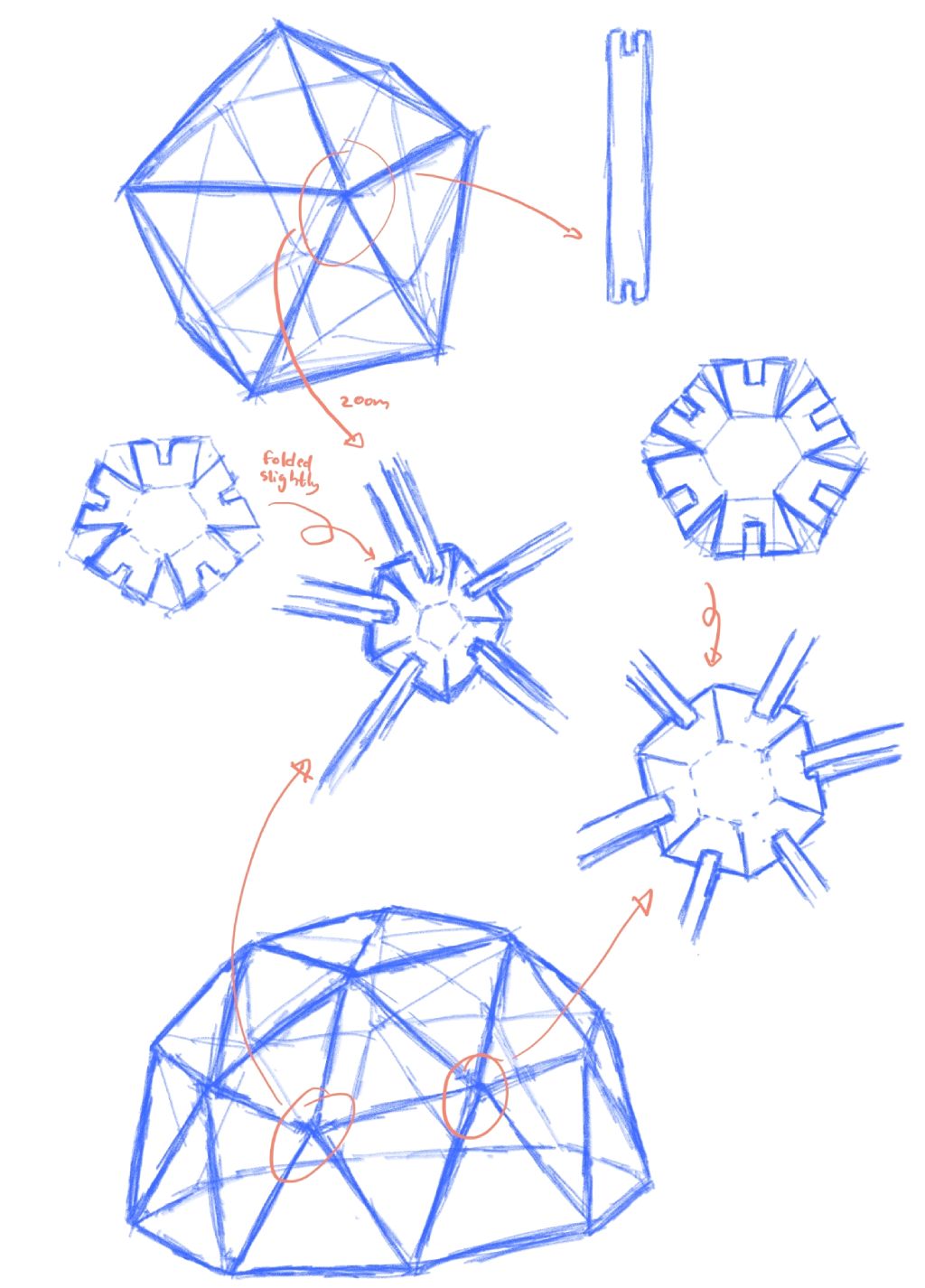
Further Development
The icosahedron that we have constructed has a frequency of 1V. It can be subdivided further into 2V, 3V, and so on. The intriguing part is that the only new component that needs to be designed is a six-sided connector, as illustrated below. As for the segments, 2V will have two different segment lengths, 3V will have three, 4V will have four, and so on.