Milling Quentorres
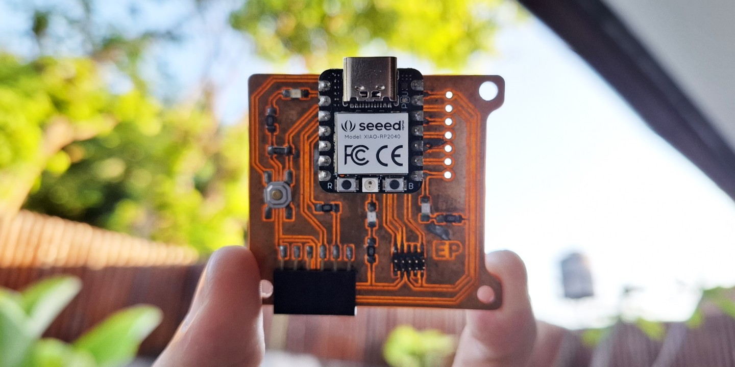
Quentorres is a entry level board perfect for learning programming born at 2024 Instructors Bootcamp held in León. Originally created by Quentin Bolsée and redesigned by Adrián Torres. It has two versions, one where the XIAO RP2040 soldered directly to the board, and the other where the XIAO is removable using connectors.
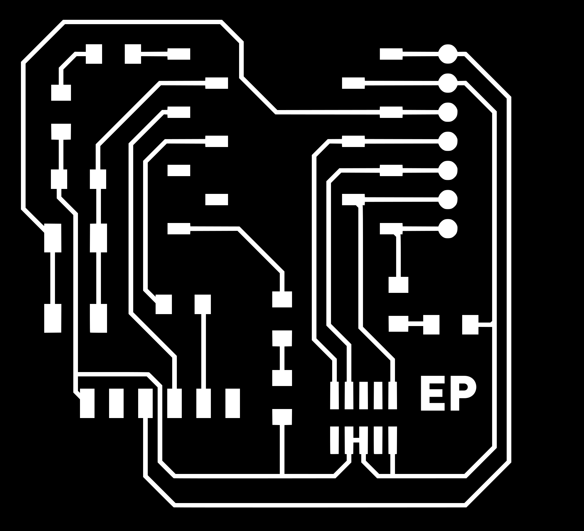
The board can be produced using the provided PNG images using Mill 2D PCB program in MODS to generate the toolpaths. The default images have been modified a little by adding flanges and holes to add possibility if we want to mount the board inside an enclosure in the future. On top of that, the QT has been replaced with my initial EP for personalization.

Generating Toolpaths
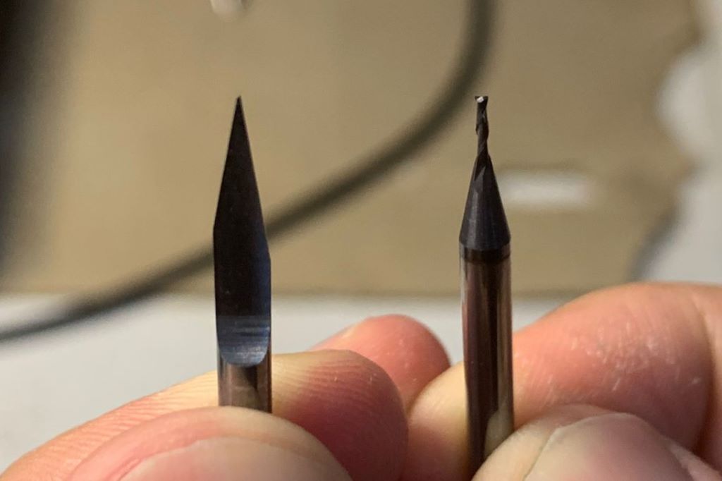
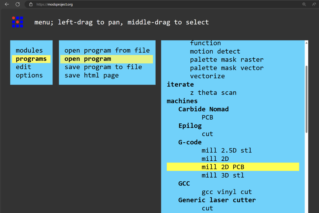
We are using Genmitsu 3018 PRO DIY for our PCB milling. The milling operations will be using 0.1 mm 20° v-bit for the traces, and 1/32" 2 flutes end mill for the drills and interior. On your MODS workspace, right click and choose programs > open program > mill 2d PCB.
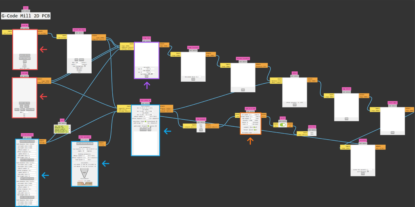
When you opened mill 2D PCB program, you will see nodes like shown above. This might looks daunting at first, but there are only few nodes that you'll need to be familiar with. These are the steps you generally need to do to generate a toolpath:
- Provide image file (PNG or SVG)
- Set machine speeds (cut, plunge, and spindle)
- Set milling bit parameters or select provided default parameters
- Optionally, you can generate tabs when cutting the outer edge of your PCB
Traces
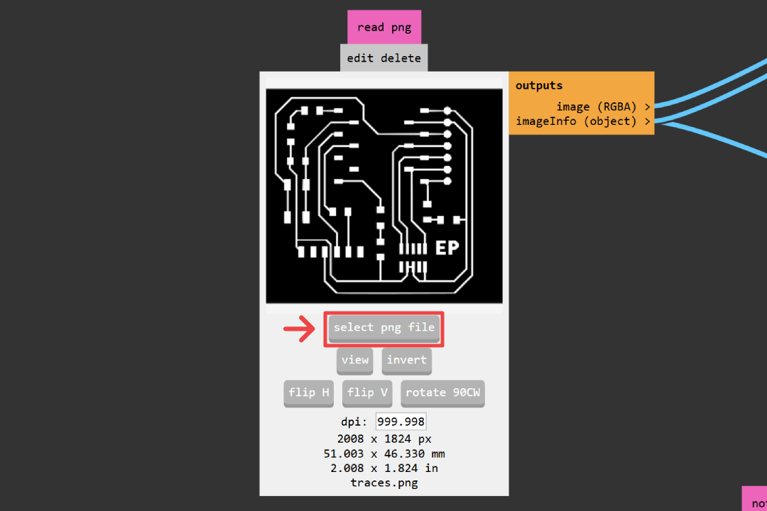
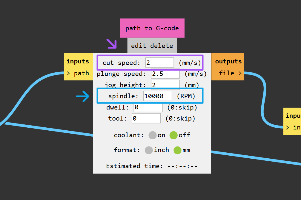
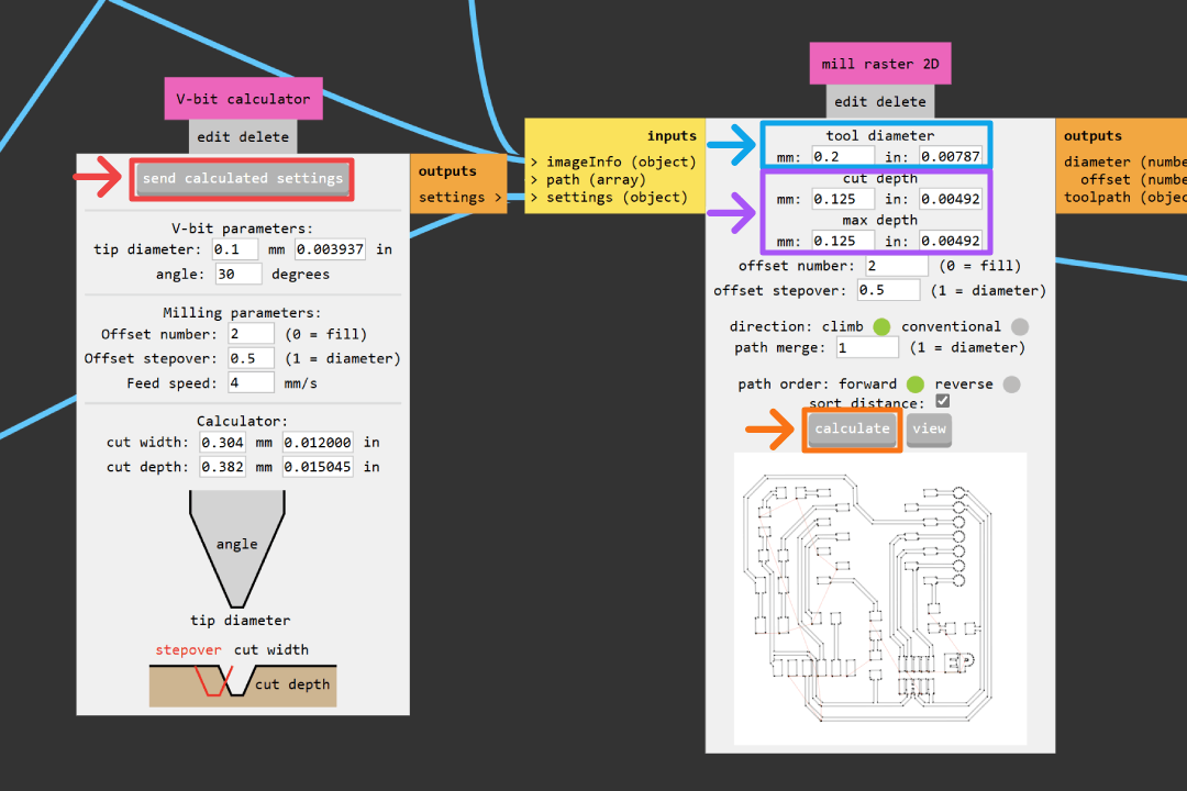
Go to read PNG node and select your traces.png image by clicking select PNG file. Next adjust your speeds in path to G-code node. Default Genmitsu 3018 PRO DIY spindle has maximum RPM of 10.000. From our group assignment, we found that 2 mm/s is the best cut speed for our v-bit that produce relatively clean cut while keeping reasonable job duration.
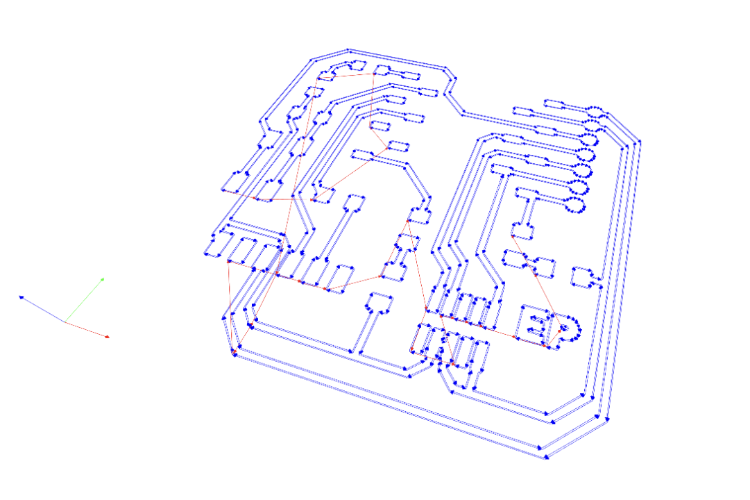
There is a v-bit calculator that we can use to set our tool settings by pressing send calculated settings. However, from our group assignment, we find that dialing these settings ourself give us a better results. The settings are 0.2 mm for tool diameter and 0.125 mm for both cut depth and max depth. Click calculate button on mill raster 2D node, then MODS will automatically generate a .nc file, open a visualization of it in a new tab, and automatically download the file for you.
Drills
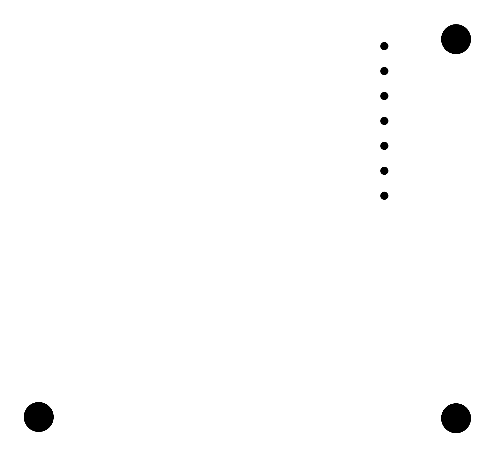
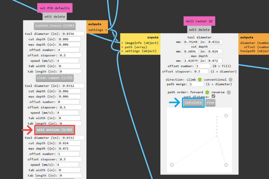
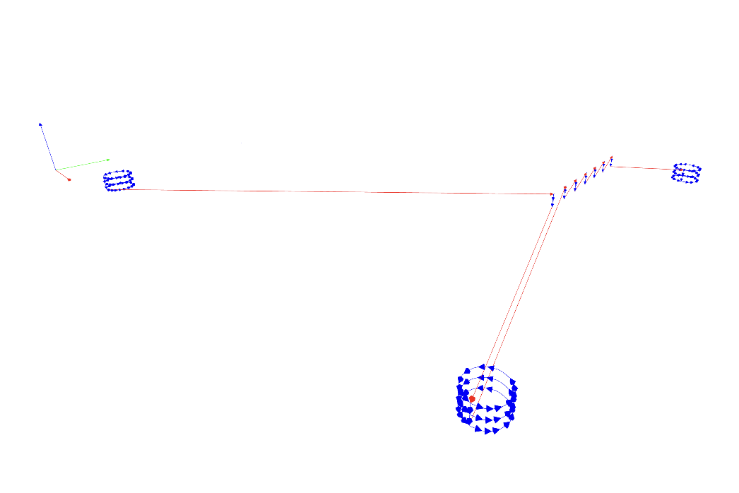
Open new MODS workspace, open the mill 2D PCB program, and input the drills.png image. We find that the default 1/32" settings works perfectly. Simply click mill outline (1/32), then click calculate to generate the .nc file.
Interior
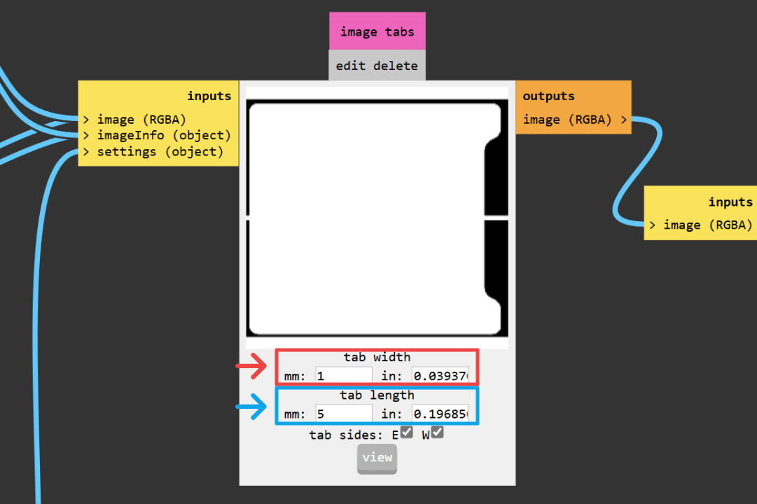
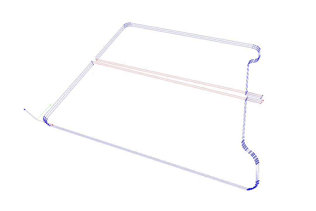
Repeat the same step as drills to import interior.png and set tool settings. However, as will be discussed later, our milling machine setup will require us to use tabs to ensure our PCB board will stay in place after the interior cutting operation is finished. So before we click the calculate button, we need to go to image tabs node, then set 1 mm for tab width and 5 mm for tab length.
PCB Fabrication
Milling
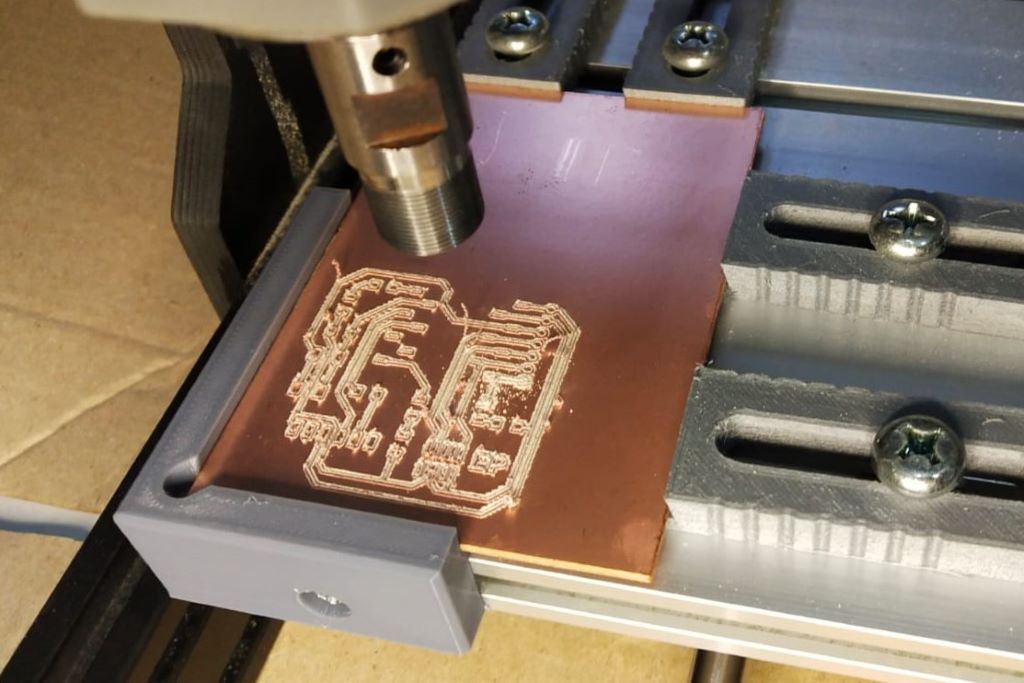
To mount the FR-1 stock, we opted to use a 3d printed PCB holder similar like this. The models are remixed to adapt it with the nuts and bolts that we have at hand.
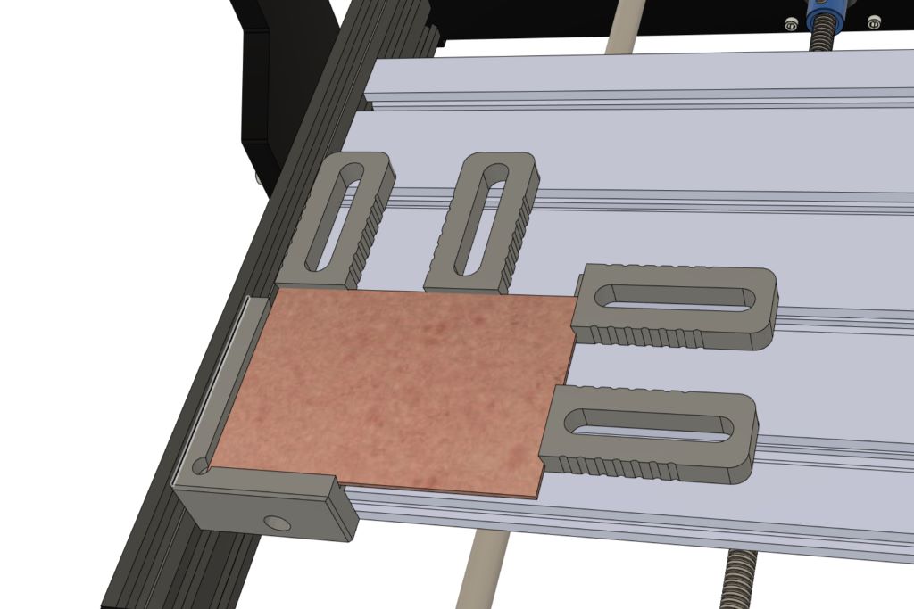
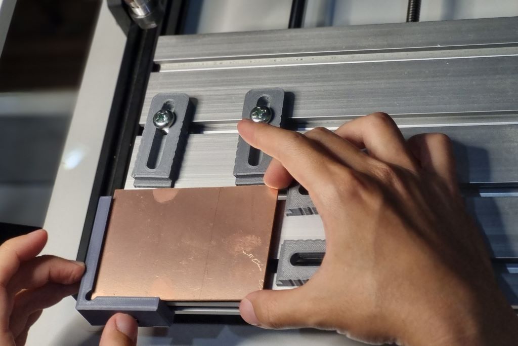
Using the PCB holder instead of using a spoilboard has it's advantages and disadvantage. It's much easier to mount and unmount our stock materials, but we lose a little bit of working area that is required for clamping. Another major issue is because there is nothing underneath the stock material, it could flex when the spindle plunges and might result in the material didn't cut all the way through. This is also the reason we need to generate tabs for our interior cutting operation. However, the biggest problem with this setup is that the material alignment is highly unlikely to be flat relative to the spindle.
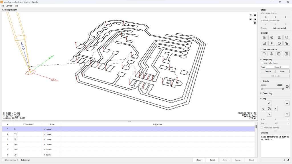
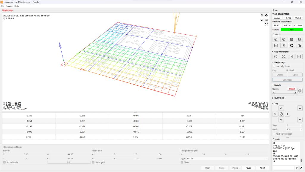
Luckily there is a heightmap feature in Candle, the control software that came 3018. This feature is really similar to what many 3d printers nowadays achieve a perfect first layer. First we import our .nc file generated by MODS, then we could create a height map by probing our stock material with our drill bit. To do this, you need to have a Z-probe and make a non-permanent modification. For detailed instructions, please refer to this guide. From the generated map, the machine will adjust it's Z position when performing the cut operation and compensate the unevenness of the material.
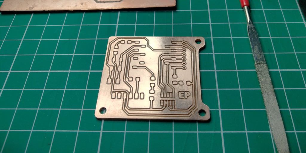
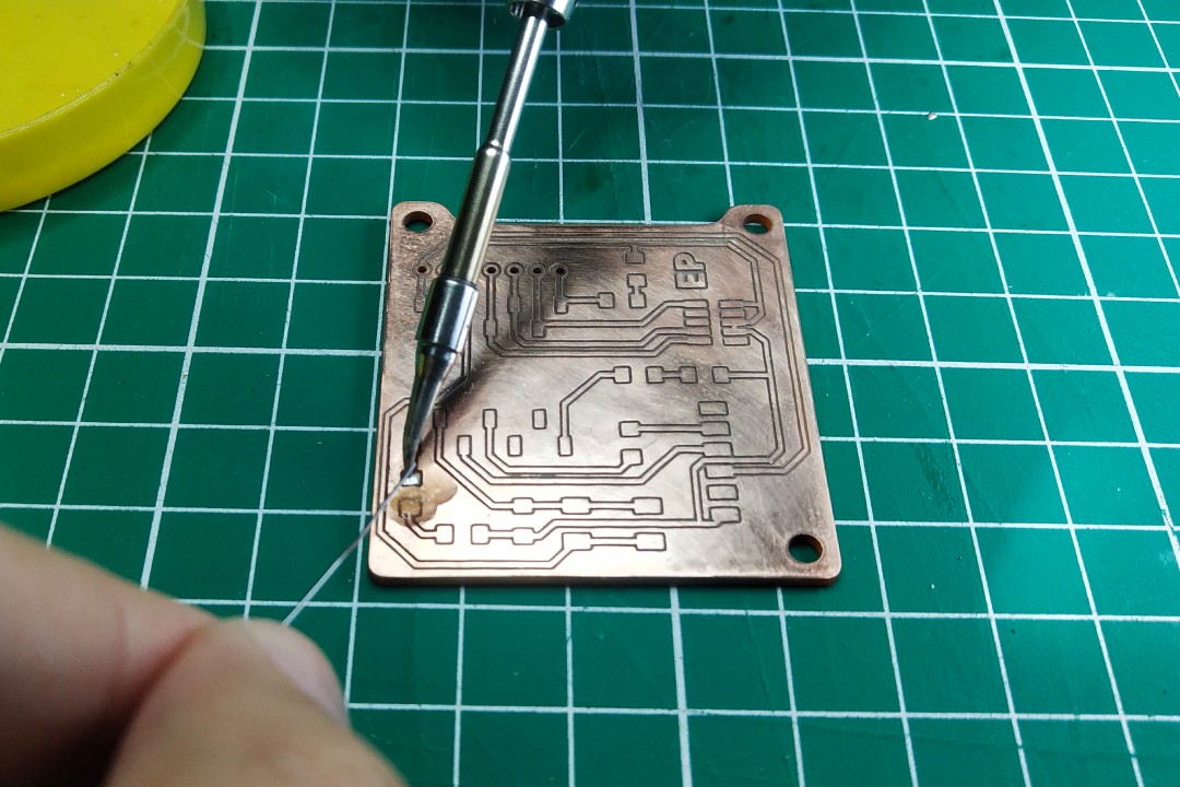
After breaking the PCB from the tabs, we sand down the outline where the tabs were using a rotary tool, then wet sand the copper surface with 800 grit sand paper. After that we should test continuity using a multimeter to check if all the copper traces are isolated from one another, no disconnected trace, and no shorted trace. Once we verify the milling result, clean the pcb with water and dish soap, removing any oil and milling residue to prepare the board for stuffing.
Soldering XIAO
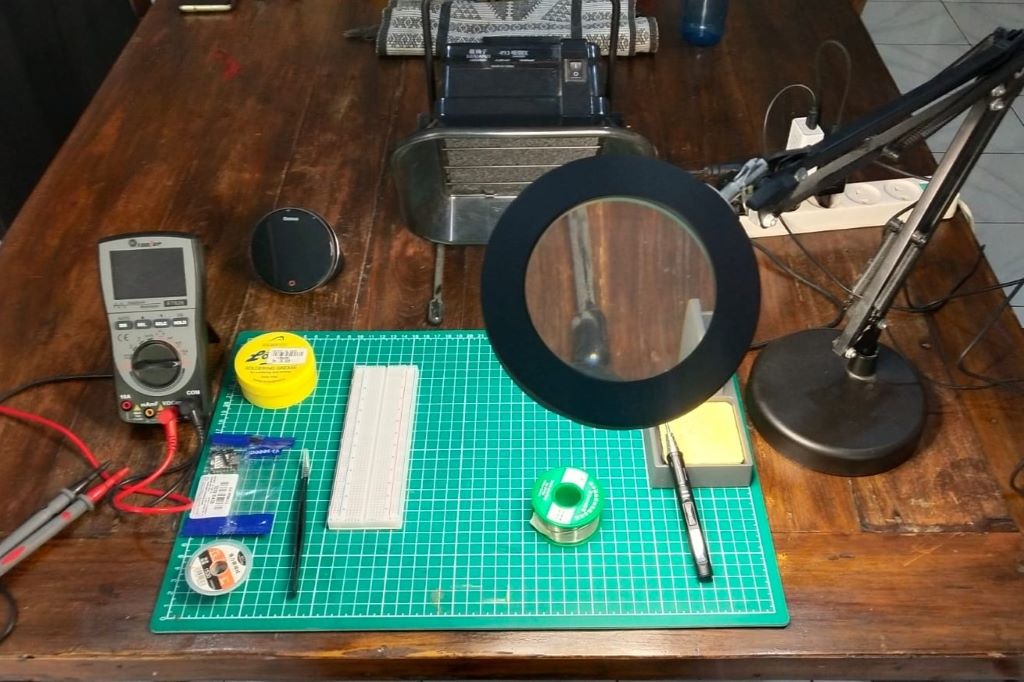
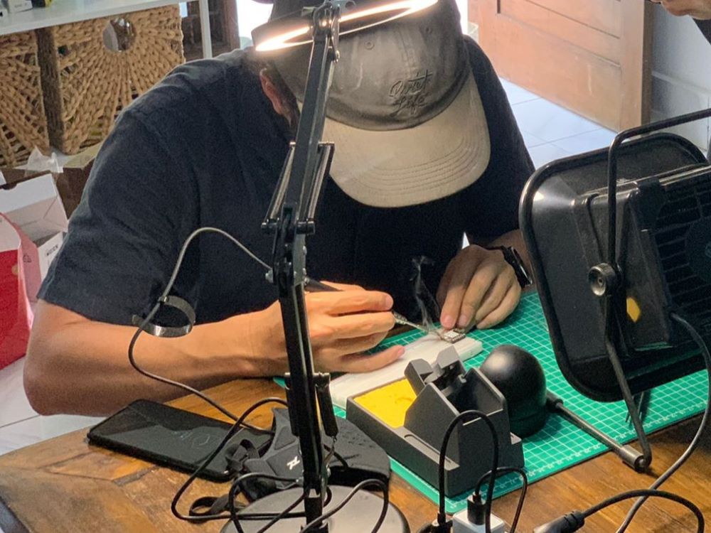
First we setup our soldering workspace. We learned that quality equipment will make a huge difference in the process. Initially we try a generic soldering station and find the soldering having a hard time to melt. Then we use my personal soldering iron TS80 by Miniware and the solder instantly liquify when touching the iron.
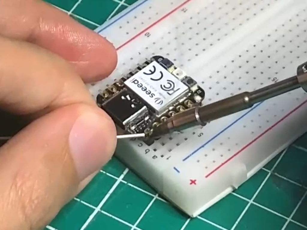
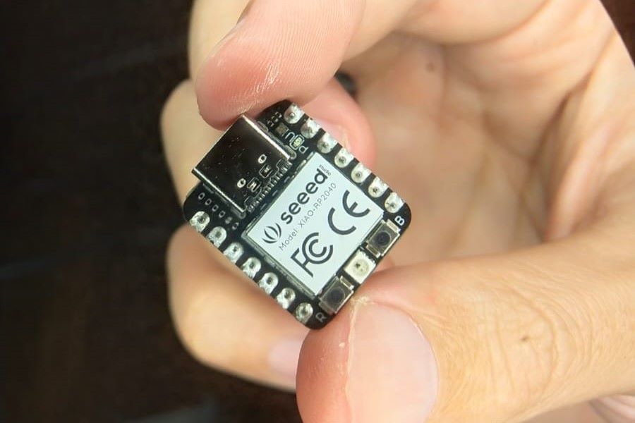
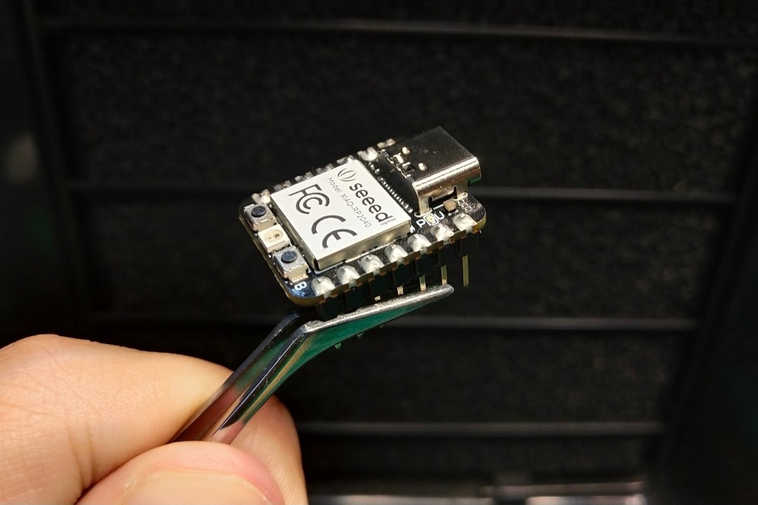
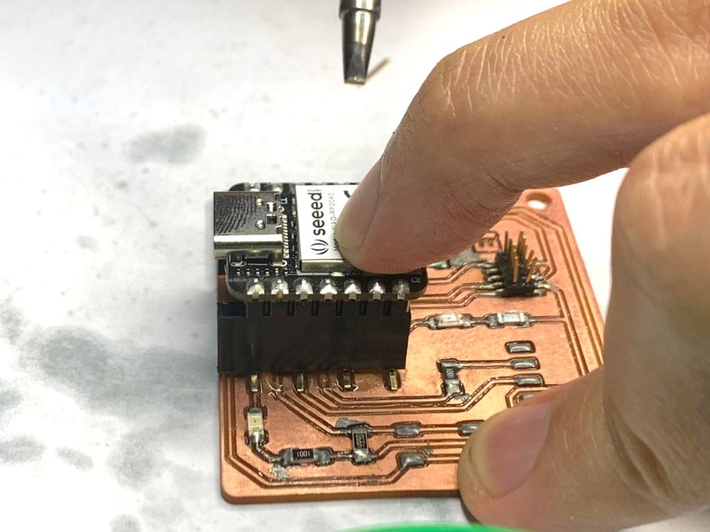
We prefer our XIAO to be removable, therefore we need to solder the 7 pos pin that come with it. To help the soldering process, we mount the pin on a breadboard, place the XIAO, then solder all the pins on both side.
Stuffing Quentorres
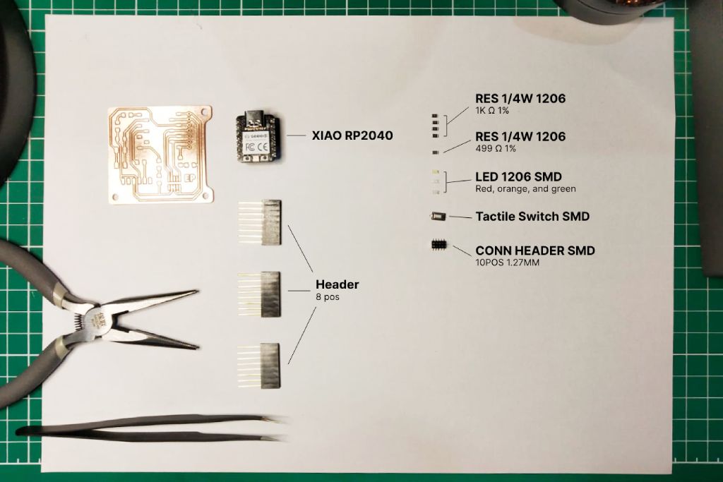
Next we will be assembling our Quentorres. We collect all the required components and laid it out bellow. Unfortunately we are missing the CONN HDR 7POS 0.1 TIN SMD and CONN HEADER SMD R/A 6POS 2.54MM. SMD components are generally hard to come by in Indonesia and even worse in Bali, so we have to try improvising by modifying an 8 pin THT (through hole) header.
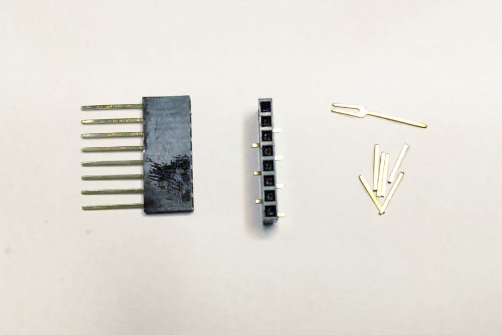
Here are some steps for modifying the incompatible components:
- We only need 7 and 6 pos header, so first we pull out the excess pins.
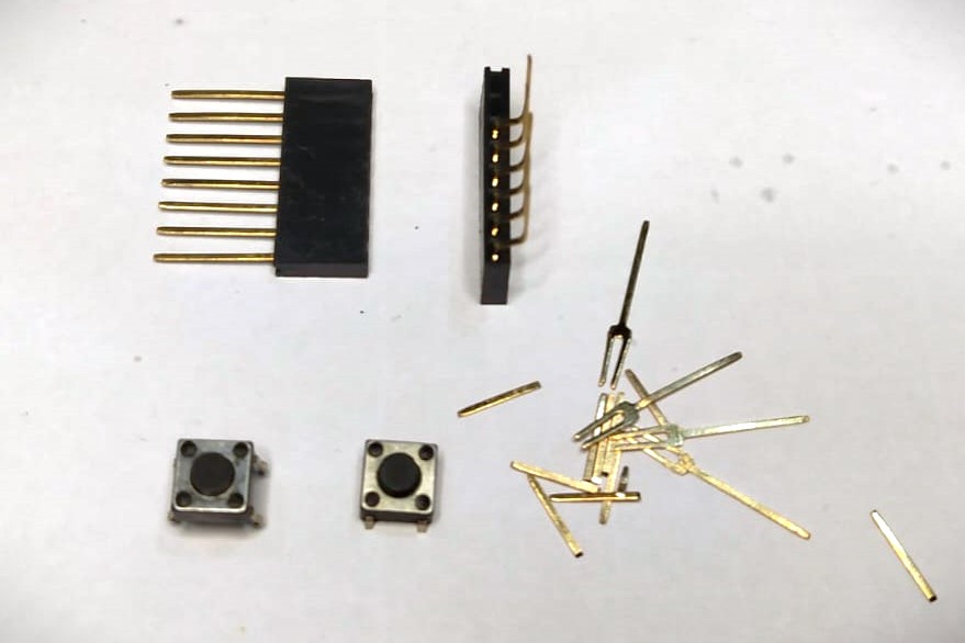
- Then we bend the pins and cut the excess to a reasonable length.
- For the button, we simply need to bend the pins a little outward and cut the pin to match the PCB layout while have the body lay flat on the surface.
Next we add a solder to one pad for each components. Use flux generously to help the process. Then we place one component at a time at their respective place, hold it in place with a tweezer while you remelt the solder. Then add solder to all the remaining pads. Repeat this process with all the components.
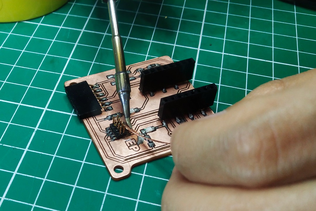
For soldering the headers for the MCU, we need use the XIAO board to help align them. This is important to make sure the alignment is correct, otherwise we might not be able to plug the XIAO board later. The fact that we also use a non standard SMD header makes aligning the header even harder.
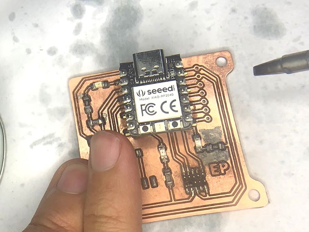
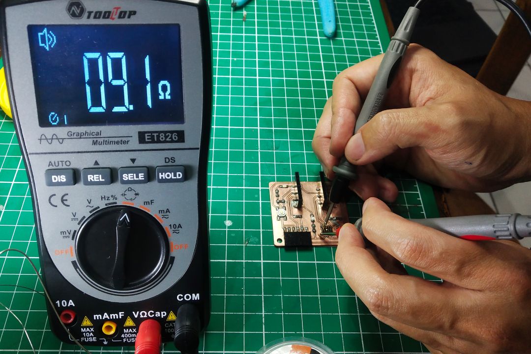
Once all the components are soldered, we should check if the components are soldered on the correct position by doing continuity test again using a multimeter. Check if all the tracks are connected from end to end and check whether the tracks are isolated from one another. If you find some that accidentally connected, you might have accidentally created a solder bridge between them that you can simply fix by cleaning up the excess solder. Another possible reason is you might still have residual copper left between tracks, which you can remove using sharp tool like Exacto knife.
Testing
Lets test the board by uploading a program to it. First we need to setup our Arduino IDE so it can recognize XIAO board by following this Seeed Studio guide. Then we use the blinking light example, edit the pin number, optionally adjust the blinking speed, and upload it to the board. We will discuss more in depth about embedded programming in upcoming weeks assignment.
#define LED_PIN 26

void setup() {
  pinMode(LED_PIN, OUTPUT);
}

void loop() {
  digitalWrite(LED_PIN, HIGH);
  delay(1000);
  digitalWrite(LED_PIN, LOW);
  delay(1000);
}