IV. Characterizing the GS 6090 PR
Sadly, at the moment, it’s not possible to use the Lasercutter at the HRW-Fablab in a group.
Luckily I’ve the same brand of Lasercutter in my lab at the HBK. So we (Jonas, Lana and I) can think about, how to characterize and make calibration files, in the actuals cycle group :-)
The GS 6090 PR
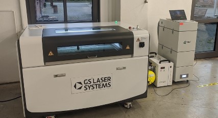
At the HBK, we have the GS 6090 PR from GS Laser Systems
| quick specs | ||||
|---|---|---|---|---|
| Laserclass | 1 | Lasertype | CO2-Laser | |
| Laserpower | 100 W | Wavelength | 10600 nm | |
| Max. engraving speed | 1000 mm/s | Max. cutting speed | 100 mm/s | |
| Resolution | 0,025 mm | smallest engravable sign | 1mm | |
| Repeatability | +-0,01 mm | drive | split drive |
The Testfile
For characterizing the Lasercutter, we decided to adapt the calibration cube from Lena Hagenauer.
Lena drew it for an Epilog Laser, combined with VisiCut.
The way to set up the cutting / engraving parameters is a bit different to GS-Laser’s RDWorks software, so we had to edit the calibration cube a bit.
For RDWorks, there is no official download source available and GS-Laser delivered the software on an USB-Stick.
I’ve found a community called rdworkslab.com around this software and the controller. There are some download links available.
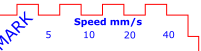
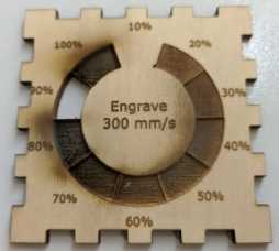
We changed E.g. the cutting speed from percent to mm/s and fixed the engraving speed to 300mm/s

RDWorks is only able to import dxf files, so we had to convert the file from svg to dxf
Because of that, the HRW-Fablab Logo disappeared and we had to import the logo directly into RDWorks
RDWorks
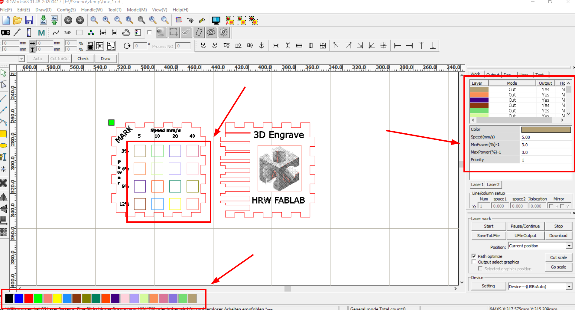
In RDWorks it’s possible to define the cutting parameter by coloring the the sketches.
So we gave every square a different color. But the amount of colors are limited !
That’s the reason, why we split the cube into 3 parts.
The edited svg file can be downloaded here
And the split RDWorks files can be downloaded here
Characterizing
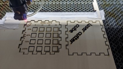
I produced the cube with 3mm Poplar wood
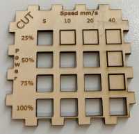
Laserpower
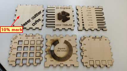
It was interesting, because the machine needs at least more than 10% Laserpower to produce a seeable result.
On the other side, is the maximum Laserpower at 90%.
The slower and higher the power, the more burnt the cutting edge is.
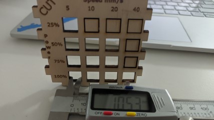
I got the best cutting result with 50% and 20mm/s
Focus
For some focus test, I draw a little sheet in Inkskape.
The file can be downloaded here
The machine has autofocus, so I just moved the table downwards.
In the Bluebox are marking lines, made with 12% power and in the Redbox are cutting lines, made with 50% power and 20mm/s speed.
It’s not so good recognizable in the picture, but with the highest distance, the beam is more wider and the cutting line is more burnt.
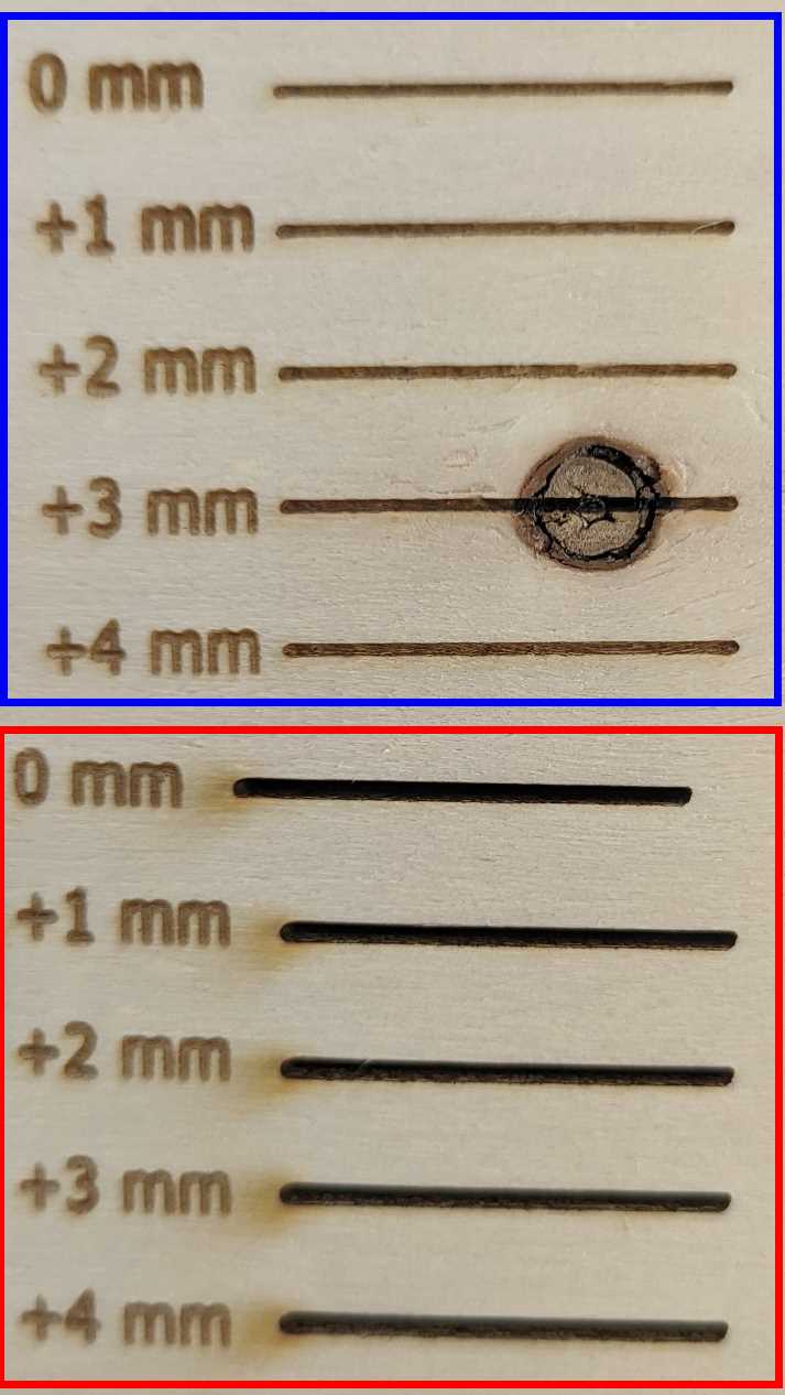
I made another interesting test. Back to autofocus, I made a cut on the top left border of the machine and one on the bottom right.
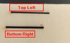
It looks like the focus needs to be calibrated.
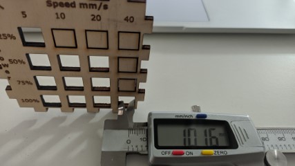
Kerf
I made the experience, that the kerf is dependent on the cleanliness of the cut edge.
The less burnt the cut edge, the thinner the cut line.
After making the tests, I went over to produce my parametric design.