III. application programming with the MIT app inventor
For this assignment, I would like to make an android app for monitoring and controlling my Serial Network.
The HC-05 Bluetooth Module is a ‘stand alone’ serial device, which can easily implemented, as a bridge, in my network. It sends serial data with 9600 baud, so I can use my node sketches without big modifications.
In the past I heard about the MIT App Inventor, but, for me, there was never a reason to program user interfaces. So this is completely new for me.
I’ve red, that this tool is easy to use and very good for beginners. PERFECT ! So I decided to use this weeks assignment to have look and practice the work with this cloud tool.
My first walking attempts
After a quick search I found a little tutorial from Engr Fahad.
That gave my a first quick introduction, how this tool works. I used my echo hello-world board from the ‘Electronics design’ week for this first steps.
The code from the tutorial looks very similar to the one I used for my nodes. I’ve modified the code and adapted it, to the needing’s for my board
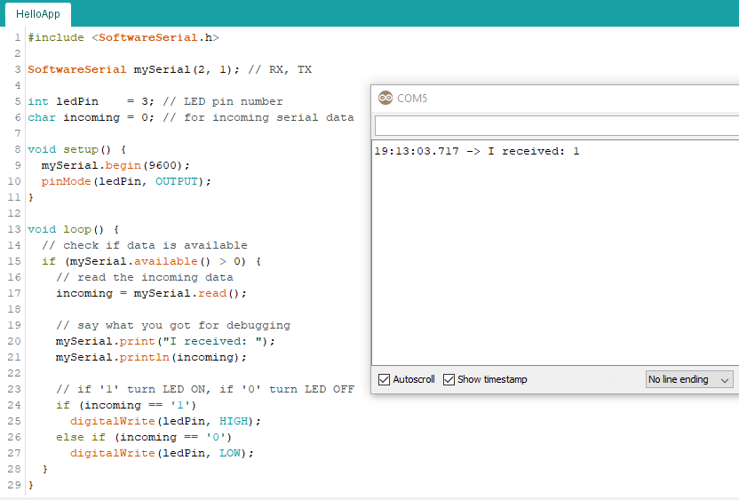
tested the sketch within the serial monitor and went through the tutorial. I don’t explain it in detail here and just show a view screenshots, I’ll do it later with my SerialNetwork App.
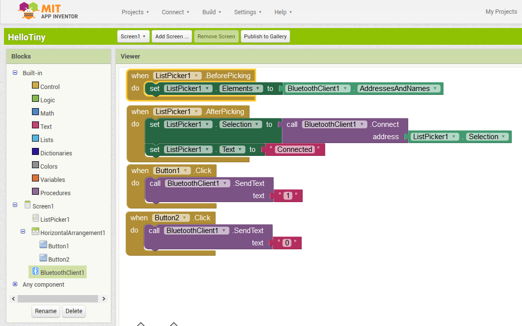
These are the finished code blocks
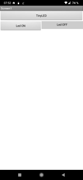
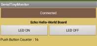
and this is how the app on the smartphone looks like
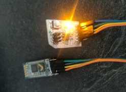
and the first successful test
So far…so good…
So let’s see, if I’m able to build my own serial network monitor
Part1: the echo hello-world board
I’ll ‘program’ my app in three steps and start creating the app for my echo hello-world board.
When everything is working properly, than I go ahead with the Nixie Tube output device and finally with the the TCRT5000 Sensor Board
preparing the sketch
First I have to customize my SerialNode sketch. I’ve implemented a function, that the board will send a 1PB message, when the push button is pressed AND no data comes in.
#include <SoftwareSerial.h>

SoftwareSerial mySerial(1, 2); // RX, TX

int node_id  = 1;    // node id
int ledPin   = 3;    // LED pin number
int buttonPin = 4;   // Button pin number
int buttonState = 0; // variable for reading the pushbutton status
int incoming = 0;    // for incoming serial data

void setup() {
  mySerial.begin(9600);
  mySerial.setTimeout(10);  // Set Timeout for separated numbers
  pinMode(ledPin, OUTPUT);
  pinMode(buttonPin, INPUT_PULLUP);
}

void loop() {
  buttonState = digitalRead(buttonPin);

  // check if data is available
  if (mySerial.available() > 0) {
    // read the incoming data
    incoming = mySerial.parseInt();

    // check if incoming data is for me
    // if so and data ends with '1' turn LED ON, when data ends with '0' turn LED OFF
    if (incoming == node_id * 10 + 1)
      digitalWrite(ledPin, HIGH);
    else if (incoming == node_id * 10)
      digitalWrite(ledPin, LOW);
    // send '1PB', when the Push Button is pressed and no Data comes in
  } else if (buttonState == LOW) {
    mySerial.print("1PB");   // ATTTENTION : mySerial.println DOESN'T WORK !!!
    delay(250);
  }
}
start designing the app
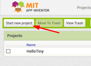
create a new project
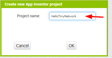
After login into the app inventor with a google account, we Start new project
and name it E.g. HelloTinyNetwork
In the project list, we click on the new entry
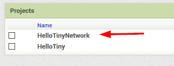
and start from scratch
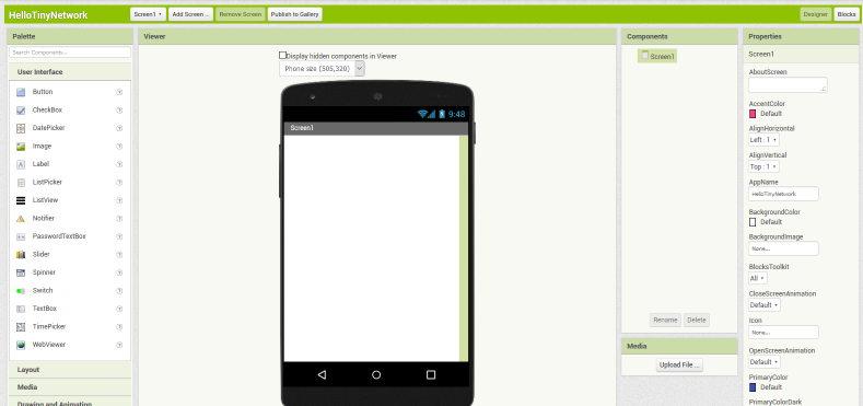
changing background color
I would like to give the app the same touch as my webpage, so I start with changing the background color.
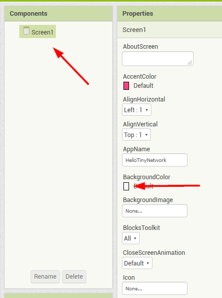
In the Components list, we click on Screen1 and in the Properties list, are lot’s of options.
There we activate the BackgroundColor option
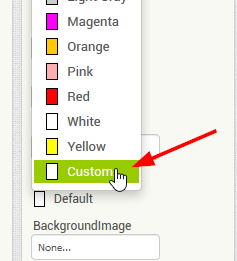
choose Custom
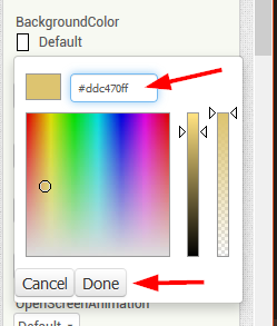
and change the color code to #DDC470 (this is the code from my extra.css)
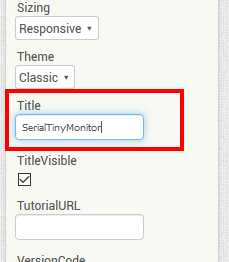
and I changed the Title to SerialTinyMonitor
placing new Components
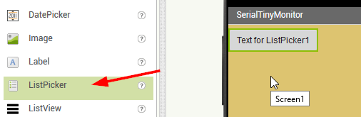
ListPicker
New components will be placed just by drag them from the left Palette and drop them to the phone’s Screen in the Viewer section.
As described in the mentioned tutorial, I start with a ListPicker for selecting a Bluetooth device. The assignment of functions will be explained later!
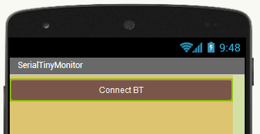
And did the following changes
BackgroundColor to #795649
Width to Fill parent
Text to Connect BT
TextColor to white
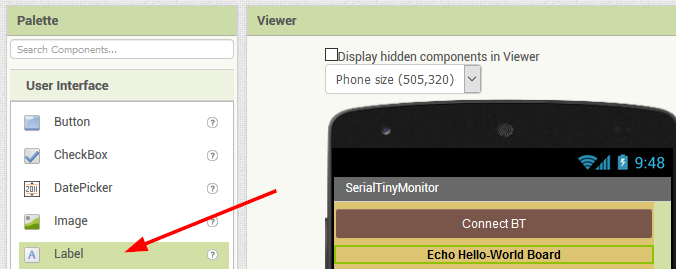
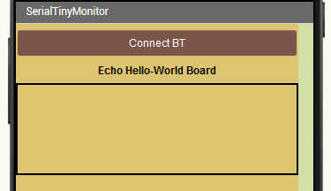
placing a label
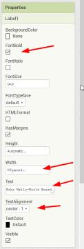
First I placed a Label and changed the following Properties
FontBold      : checked
Width         : Fill Parent
Text          : Echo Hello-World Board
TextAlignment : center
Horizontal Arrangement
I would like to place 2 buttons for the onboard LED (ON/OFF). So first we pick and place the HorizontalArrangement from the Palette’s Layout list.
And changed
Width: Fill parent
BackgroundColor : #DDC470
Adding Buttons
From the User Interface list, we add 2 Buttons and place them inside the HorizontalArrangement
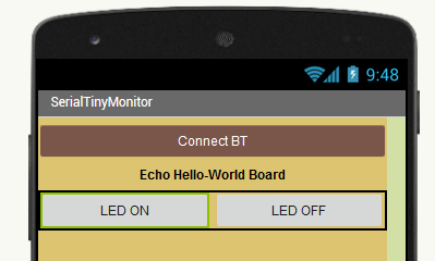
For each button we change Width to Fill parent and the Text: LED ON for Button 1 and the Text: LED OFF for Button 2
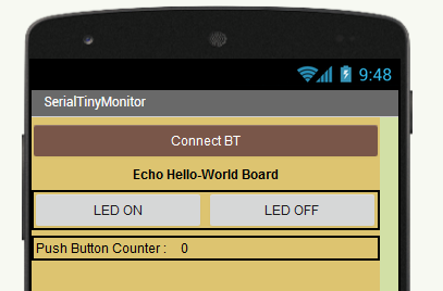
Adding Push Button Counter
To add a Push Button Counter, we have again to place a HorizontalArrangement, with the same settings as above.
Inside the Arrangement we put 2 Labels and name the left one Push Button Counter : and the right one 0
Adding Bluetooth Client
To be able, to connect via Bluetooth, we have to add a BluetoothClient from the Connectivity section.
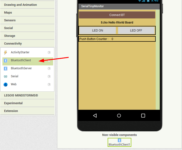
This Component is shown in non-visible components under the device.
The design is now finished and we can go ahead with placing the code blocks.
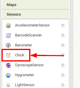
Adding Clock
To be able to read incoming data, we need an event timer. This is the reason, why we need a clock component.
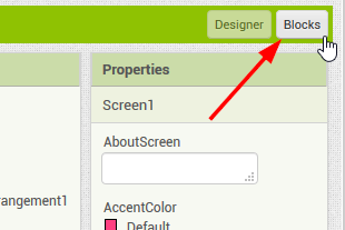
Placing the Logics
On the top right we click on Blocks
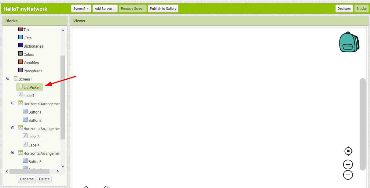
Bluetooth Devices List
After clicking on ListPicker, in the Blocks area, some code blocks appear in the Viewer
Also with drag an drop, we pick the when ListPicker1.BeforePicking
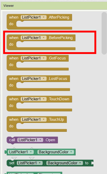
These are when -> do blocks. When this > do that
We go ahead an pick set Listpicker.Elements to
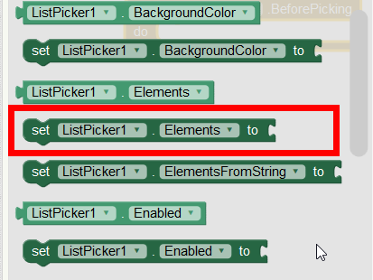
and drop it inside the above when, do block
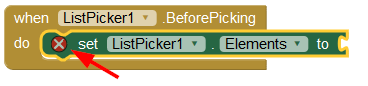
the warning sign shows us, that the logic is not completed.
In the BluetoothClient list we pick BluetoothClient.AdressesAndNames
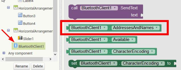
and drop it to the uncompleted block
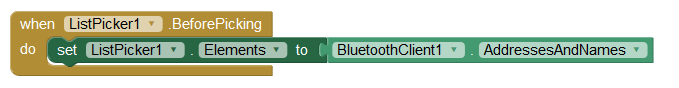
The warning is disappeard now.
This block now means, that when we click the Connect BT button in the app, a List with connected Bluetooth devices appears.
Next we make a new block and pick the when ListPicker1.AfterPicking
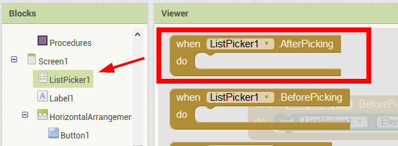
We go ahead an pick set Listpicker.Selection to
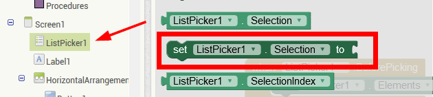
then the block call BluetoothClient.Connect adresses
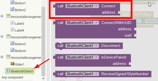
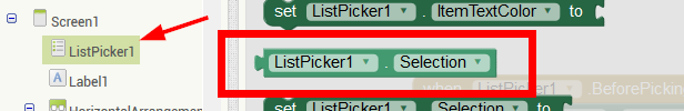
behind the block we put a Listpicker.Selection block
We go ahead an pick set Listpicker.Text to
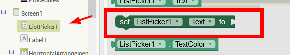
and complete the block with the empty string from the Text blocks
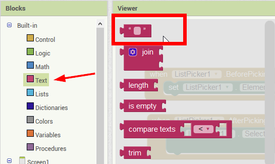
And in this text block we write Connected
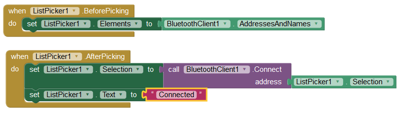
This block has now the function, to connect to the selected Bluetooth Device and after successful connection, the Connect BT button will renamed to Connected
The Bluetooth part is finished now.
Defining the Buttons
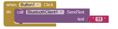
With this knowing we can now define a logic for the first button, so that the LED on the node 1 (echo hello-world board) turns on.
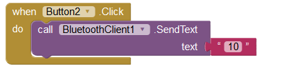
That means When Button1 is pressed -> sendText over Bluetooth -> Text = 11
In block it looks like this
Same for Button2 and LED OFF on node 1
The Push Button Counter
Now it will be exciting, let’s try to define the push button counter.
This exciting thing, took me half a day and 15 app versions. I wasn’t able to compare the incoming data and now I know why !
In the sketch for the board, I submitted the button press with mySerial.println("1PB");. That means, that a linefeed is at the end of the data and with that, my algorithm hasn’t worked.
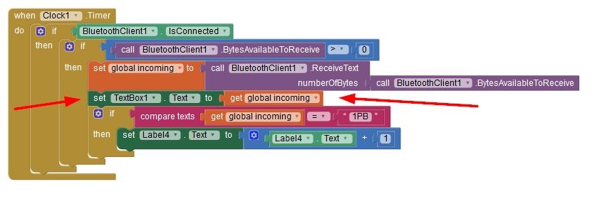
So here is the block now :
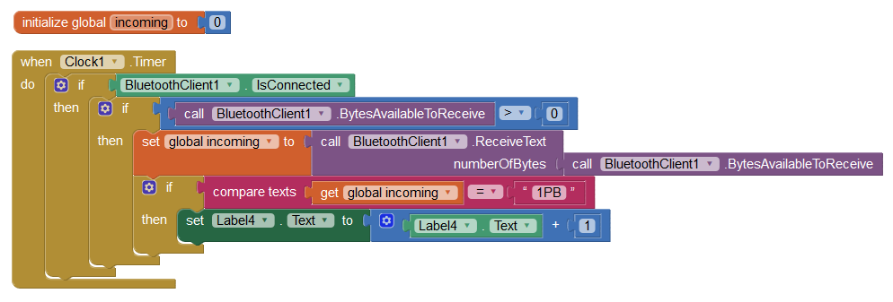
First we need a variable called incoming with the content 0. Inside this variable, the incoming data will be stored.
Then a Clock (Event) Timer is needed. When the Bluetooth is connected and data comes in, store this data in the variable incoming.
When the content of incoming is equal to 1PB, count the content of label 4 +1
First Test
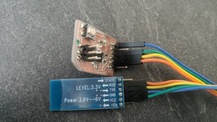
Connecting the HC-05
I’ve connected the HC-05 Module the ftdi header in that way: GND -> GND, VCC -> VCC, RX -> TX, TX -> RX
Export the apk
In the App Inventor we click on Build and App (provide QR code for .apk.
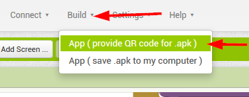
Then compiling starts
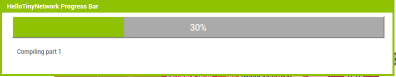
And a QR Code for download appears
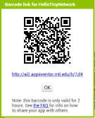
Testing the app
After scanning the code with my smartphone, I’ve downloaded and installed the app.
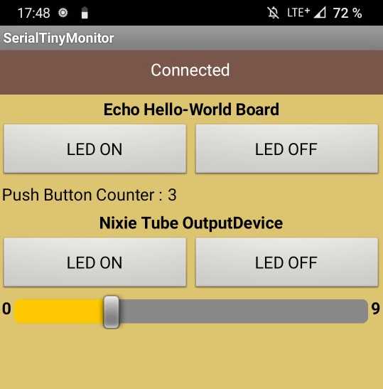
After starting it looks like this
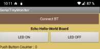
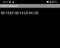
With a touch on ConnectBT a list with connected Bluetooth devices appears
After connecting I was able to turn the LED on/off and the push button counter is works perfect
Part2 : The Nixie Tube Input Device
The next step is to implement my Nixie Tube Input Device
preparing the sketch
The sketch definitely needs some preparations.
I’ve left the node_id part as is, but for displaying the numbers I used a switch case code.
Here is a snippet of it:
    switch (incoming) {

      case 0:
        digitalWrite(A, LOW);
        digitalWrite(B, LOW);
        digitalWrite(C, LOW);
        digitalWrite(D, HIGH);
        break;
The complete code is at the bottom of this page.
adding the design part
I would like turn the onboard on and off and the displayed number of the Nixie Tube should be set with a slider.
In the same way as above, I’ve added
- a
Label:Nixie Tube OutputDevice - a
HorizontalArrangementwith - two
Buttons:LED ONandLED OFF - a
HorizontalArrangementwith - a
Label:0on the left - a
Sliderwith theMaxValue:9and theMinValue:0 - a
Label:9on the right
Placing the Logics
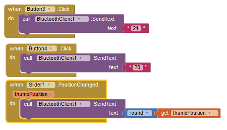
I’ve added the two buttons as above, just with another output. 21 for LED ON and 20 for LED OFF.
The Slider has one When -> Do block with the variable ThumbPosition. The content of ThumbPosition should be send via Bluetooth. In the design part, we defined the Min/MaxValue 0 - 9
Normally the Slider variable has two decimal places. That’s the reason, why I’ve added a round block from the Math section, because I want to send whole numbers only.
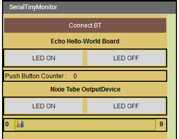
Testing the app
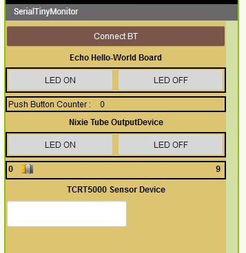
This is how the app now looks like
Pictures and videos are in the ‘Final Result’ at the bottom of this page.
Part3: TCRT5000 Input Device
Now it will be really interesting. Will I be able to display the sensor value in the app ? I expect really high data traffic and fear that the communication will break down.
preparing the sketch
The sketch is nearly the same as in the Input devices week. I just changed the output part. Send only Data, when no data come’s in.
#include <SoftwareSerial.h>

SoftwareSerial mySerial(1, 2); // RX, TX

int a, b, c;
int incomming;

void setup()
{
  mySerial.begin(9600);
  pinMode(4, OUTPUT);
}

void loop() {

  digitalWrite(4, HIGH);   //Turning ON LED
  delayMicroseconds(500);  //wait
  a = analogRead(A3);      //take reading from photodiode(pin A3) :noise+signal
  digitalWrite(4, LOW);    //turn Off LED
  delayMicroseconds(500);  //wait
  b = analogRead(A3);      //again take reading from photodiode :noise
  c = b - a;               //taking differnce:[ (noise) - (noise+signal)] just signal

  if (mySerial.available() > 0) {
    incomming = mySerial.read();
  } else {
    mySerial.print(c);
  }

  delay(50);

}
preparing the app
For a first test, I just added a Label and a TextBox
And modified the code block for incoming data
Testing the app
*** After 4 hours of testing I gave up and came to the conclusion, that it doesn’t work. I don’t know really why, but I think, that’s an electronically and/or physically issue
When I have more than 2 sending devices, the hole network freezes…***
Final Result
Here are some videos of the echo hello-world board part.
Switching the onboard led on and off…
The push-button counter…
And here are the videos of the nixie tube board.
Switching the onboard led on and off…
Changing the number with the slider…
Downloads
Here are the downloads:
HelloTiny.zip is the apk from my very first test above.
HelloTinyNetwork.zip is the apk from the finished app.
HelloTinyNetwork.aia is the app inventor file.