III. Designing a single Nixie Tube output device
As in my Input devices week, I used KiCad for the electronics design.
Detailed information about how to use KiCad are there, so I don’t explain the design process in detail here.
More Information about the tube I used, are in my final project Research section.
The ZM1040 needs an operating voltage of 170V. I’ve a NCH6100HV power converter, which needs an input of 12V min.
To drive everything with one 12V power supply, I used an AMS1117 5.0 voltage regulator for the microcontroller circuit.
Bill of Material
In summery, for the single Nixie Tube output board, the following parts are needed:
- 12V Power Supply
- 1x NCH6100HV StepUp Converter
- 1x ZM1040 or ZM1042 Nixie-Tube
- 13x female d-sub pin
- 1x K155id1
- 1x ATtiny44
- 1x AMS1117 5.0
- 1x Capacitor 1.0 uF
- 1x SMD LED (blue)
- 1x 1x6 Pinheader male (horizontal)
- 1x 2x3 Pinheader male (vertical)
- 1x 2x5 Pinheader male (vertical)
- 1x 2x5 Pinheader female (vertical)
- 3x 1x2 Pinheader male (horizontal)
- 1x Resistor 1K
- 1x Resistor 10K
- 1x Resistor R100
- 1x Resistor 6.8K / 1W
The final schematics
For a single tube I thought, a little bare round pcb would be nice. But that means, that the hole circuit has to be UNDER the tube. First, I made the schematics and tried to place and connect everything on one side, but I quickly got to the point where I realized that it was not possible to.
Many traces would needed to be bridged and at this point, I’m still not able to mill double sided pcb’s with my CNC3018. I first have to work out a workflow for it.
So I decided to make two rounded boards which are connected with pinheaders. Because of that, I was able to eliminate nearly all bridges. NEARLY, means....there is ONE left ¯\_(ツ)_/¯
This is the final schematics
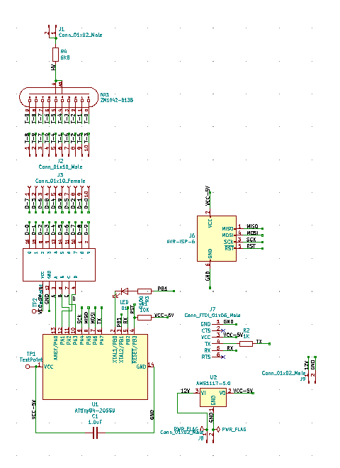
Unlike my other boards, I used an ATtiny44, because it has more i/o pins, which I needed for the K155id1 driver IC.
In the schematics, the Tiny is named ATtiny84, but the pinout is the same, so it’s only a cosmetically issue and of course, you could use an ATTiny84, too
I had two i/o pins left, where I connected a blue LED. Normally the cathode of the LED has to be connected to ground, but that wouldn’t be possible, without a bridge. I used an output pin from the microcontroller and in the program code, I defined it as low
As you can see, there is a Testpoint on the VCC input of the ATtiny. I used it as a solder pad, for the last remaining bridge from the 5V output of the AMS1117 and the VCC input of the ATtiny44.
For the power supply, I just put a 1x2 Pinheader on the controller board as VIN. To connect the NCH6100HV, I put also a 1x2 Pinheader as 12V VOUT on it.
On the tube board I put a 1x2 Pinheader for 170V high voltage in. To avoid polarity reversal, I decide to just make a VCC line !!!
The GND OUT from the NCH6100HV doesn’t need to connect !!!
The final board layout
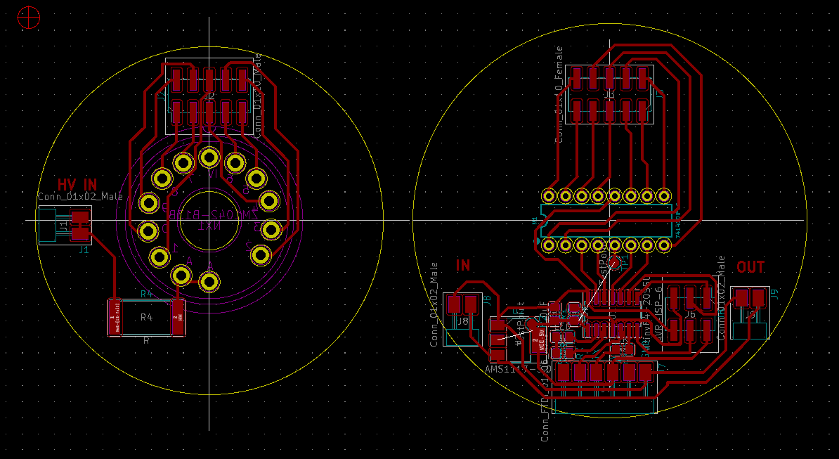
Just for my optical eye, I made the tube board (the left one in the picture) a little bit smaller, than the controller.
In each of the edge cut circles, you can see, that I drew a gray cross in the middle of them. I used the lines as an orientation for placing the tube socket in the middle and for an overlapped placement of the boards pinheader.
Because I would like to place the tube on the backside of the pcb, I had to flip the socket !
On the controller board, you can see the last remaining ‘airwire’ :-/ I’ve used a normal wire, to connect the points.
If you compare the K155id1 with the ZM1040 pinout, you can see, that it doesn’t match anymore. That’s also a result of eliminating some bridges. It’s not a really problem, because it can be fixed on the software side.
Download
The Kicad Files with the generated gerber files can be downloaded HERE