IV. Milling, Making and Testing
Again I used Flatcam for gcode preparation, but this time, I want to use my own designed edge cut.
Sadly, in FlatCAM8.5 is no option for that, so we have to do a workaround, to be able, to cut own shapes.
Custom edge cut workaround
FlatCAM part
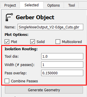
In FlatCAM we have to open the SingleNixieOutput_V2-Edge_Cuts.gbr and in the Isolation Routing section, we choose as Tool diathe edge cut end-mill, which is 1.0 mm in my case and 1 pass
And confirm with a click on Generate Geometry
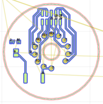
Now you see, that there is an inner- and an outerline around the edge cut
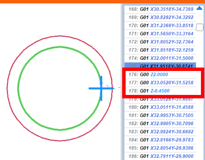
In the new generated SingleNixieOutput_V2-Edge_Cuts.gbr_iso we define the following settings
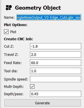
Cut Z: -1.8
Travel Z: 2.0
Feed Rate: 60.0
Tool dia: 1.0
Multi-Depth: Check
Depth/pass: 0.45 !!!
And confirm with Generate
In the SingleNixieOutput_V2-Edge_Cuts.gbr_iso_cnc we just Export G-Code now.
So far…so good…BUT (!!!) we have now an inner- and an outer cutting line.
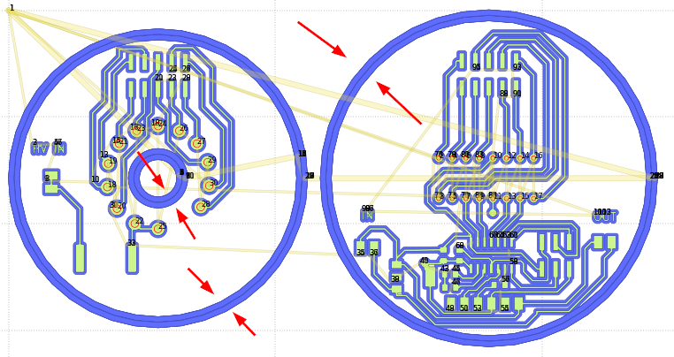
I would like to use the inner cutting line for the inner circle in the Tube Board and the outer cutting lines for the board cut outs.
Estlcam part
When we open the g-code file in Estlcam, there is a nice preview. With a click on a line in the gcode, the preview window shows, which position the spindle has on that point.
Now there are two options :
Just mark the starting point, click the play button, wait until the cutting line change, then pause/stop milling and do it with the cutting lines you want.
Or open the g-code file in an editor and delete the parts, you don’t want to cut.
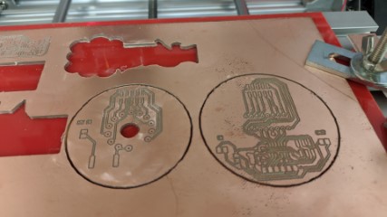
Milling
Here are some pictures of the milling process.
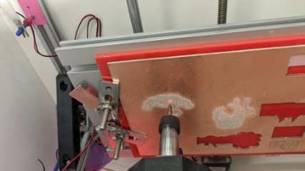
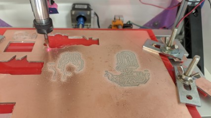
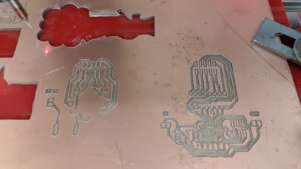
For the THT Holes, I used a 0.7mm drill bit. This is big enough for the K155id1 and the ZM1040 socket.
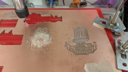
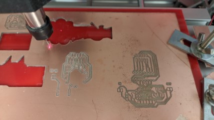
And the custom edge cut, with a 1.0mm end mill.
During sanding and cleaning the board, I accidentally cut a trace. I fixed it with a single line from a wire.

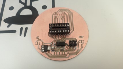
Soldering and testing
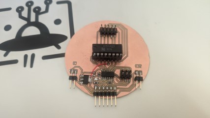
I assembled the microcontroller board step by step and did some testing between them.
First I soldered the smd parts, the IC Socket and the ISP Header
blink test
This is enough to make a blink test.
I flashed this code for testing
//Output Device LED blink + serial output test

#include <SoftwareSerial.h>
SoftwareSerial mySerial(7, 8);

int LED_GND = 10;
int LED = 9;
int wait = 500;

void setup() {
  mySerial.begin(4800);
  mySerial.println("Output Device LED blink + serial output test");
  pinMode(LED_GND, OUTPUT);
  pinMode(LED, OUTPUT);
  digitalWrite(LED_GND, LOW);
}

void loop() {
  digitalWrite(LED, HIGH);
  mySerial.println("LED On");
  delay(wait);
  digitalWrite(LED, LOW);
  mySerial.println("LED Off");
  delay(wait);
}
serial output
Than I soldered all connectors to the board
with the same sketch, I connected the board via ftdi to the computer and opened up a terminal window in the arduino ide
good !!!
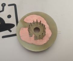
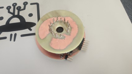
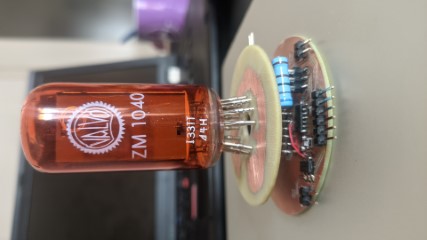
making the tube board
The tube board needed a little preparation. I’ve only double sided pcb’s on stock, but the socket pins should be placed with the tht-holes on the backside.
My first thought was to sand the side and remove the copper completely, but during sanding, I saw that the board got a nice surface by leaving some rest of copper on it.
Of course with prevention of short cuts.
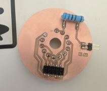
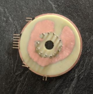
And here the backside
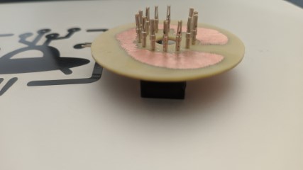
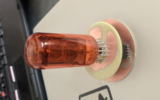
putting the boards together
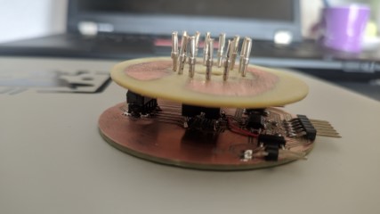
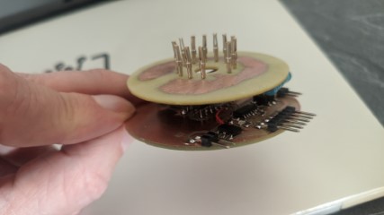
with the tube on top
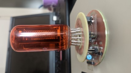
and again the little blink test
preparing for first lightning up
First I tried the microcontroller board with a 12 V power supply to see, if the AMS1117 5.0 works correctly
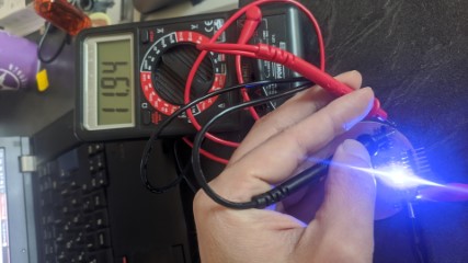
The Multimeter is connected to the 12V output connector of the board. On this pins, the NCH6100HV will be connected.
The LED blinks as it should, so nothing is fried. :D
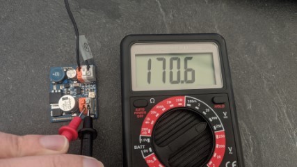
Than it’s time, to set the correct output voltage of the NCH6100HV to 170V DC
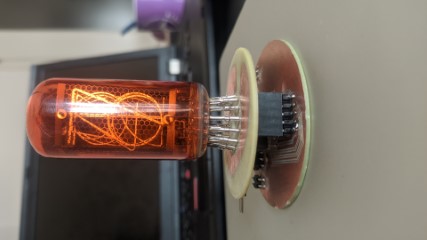
lightning up
For my first test I used the sketch as on my K155id1 page
I just edited the header
int A = 0;
int B = 2;
int C = 3;
int D = 1;
int LED_GND = 10;
int LED = 9;
int wait = 250;

void setup() {
  pinMode(A, OUTPUT);
  pinMode(B, OUTPUT);
  pinMode(C, OUTPUT);
  pinMode(D, OUTPUT);
  pinMode(LED_GND, OUTPUT);
  pinMode(LED, OUTPUT);
  digitalWrite(LED_GND, LOW);
  digitalWrite(LED, HIGH);
}
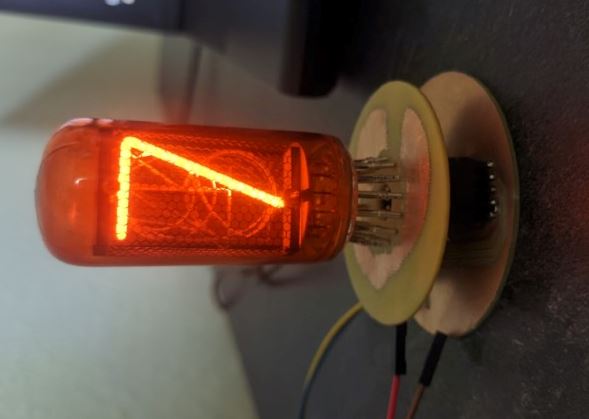
After connecting the NCH6100HV and 12V power, I got my first success !!!
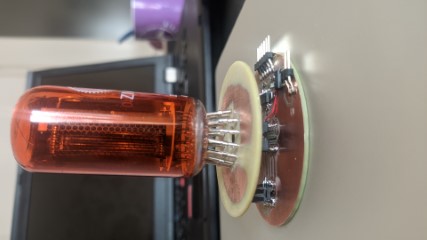
As mentioned before, the pin mapping doesn’t match anymore, so I expected a little mismatch
I added a serial output to the sketch, so I was able to compare the numbers and reassigned them.
GREAT SUCCESS
finished device
Here is a short clip of the finished device.
The sketch is available HERE In the sketch I marked the the old and the new pin mapping