III. Programming and Testing
onboard LED
I start testing the board with a modified version of the blink example sketch.
The Variable LED_BUILTIN is not know by the ATTinys, so I had to change that to the pin number, where the LED is connected to
// the setup function runs once when you press reset or power the board
void setup() {
  // initialize digital pin LED_BUILTIN as an output.
  pinMode(3, OUTPUT);
}

// the loop function runs over and over again forever
void loop() {
  digitalWrite(3, HIGH);   // turn the LED on (HIGH is the voltage level)
  delay(1000);                       // wait for a second
  digitalWrite(3, LOW);    // turn the LED off by making the voltage LOW
  delay(1000);                       // wait for a second
}
Trying to upload the sketch with the FabTinyISP runs again into trouble, so I used the Wavgat for uploading via ISP.
That worked flawless and the hello board starts to blink !
push button
Next step is test the button, combined with the LED. For that I used the ‘button example sketch’ and modified it a bit.
I changed the pin numbers and enabled the internal pullup resistor for the button.
// constants won't change. They're used here to
// set pin numbers:
const int buttonPin = 4;     // the number of the pushbutton pin
const int ledPin =  3;      // the number of the LED pin

// variables will change:
int buttonState = 0;         // variable for reading the pushbutton status

void setup() {
  // initialize the LED pin as an output:
  pinMode(ledPin, OUTPUT);
  // initialize the pushbutton pin as an input:
  pinMode(buttonPin, INPUT_PULLUP);
}

void loop() {
  // read the state of the pushbutton value:
  buttonState = digitalRead(buttonPin);

  // check if the pushbutton is pressed.
  // if it is, the buttonState is HIGH:
  if (buttonState == LOW) {
    // turn LED on:
    digitalWrite(ledPin, HIGH);
  } else {
    // turn LED off:
    digitalWrite(ledPin, LOW);
  }
}
serial communication
Now let’s test the serial communication.
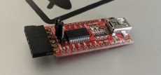
For testing the serial output we need an FTDI-Adapter. I modified it, by changing the male header to female header, for a previous project.
The Tiny has no hardware based serial output, so I used the Arduino SoftwareSerial Library in my test sketch.
This sketch is now a toggle switch (Push On - Push Off) for the LED with serial output.
#include <SoftwareSerial.h>
SoftwareSerial mySerial(2, 1); // RX, TX pins of the ATTiny

const int buttonPin = 4;  // the number of the pushbutton pin
const int ledPin =  3;    // the number of the LED pin

int buttonState = 0;      // variable for reading the pushbutton status
int lastState = 0;        // variable for toggling the LED on or off


void setup() {
  mySerial.begin(4800);
  mySerial.println("Hello, world");
  mySerial.println("start sensing");

  pinMode(ledPin, OUTPUT);
  pinMode(buttonPin, INPUT_PULLUP);
}

void loop() {

   buttonState = digitalRead(buttonPin);

  if (buttonState == LOW && lastState == 0) {
    // turn LED on:
    digitalWrite(ledPin, HIGH);
    lastState = 1;
    mySerial.println("LED ON");
  } else if (buttonState == LOW && lastState == 1){
    // turn LED off:
    digitalWrite(ledPin, LOW);
    lastState = 0;
    mySerial.println("LED OFF");
  }
  delay(250);
}
When the board starts it shows a welcome message and the state of the onboard LED.
By pressing the push button, the LED state changes and a corresponding message appears.

additional information
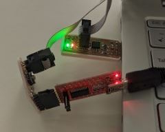
During the tests I found out, that I have to connect the FabTinyISP AND the FTDI-Adapter for upload a sketch or burn the bootloader with my DIY-programmer.
So it works now !!!
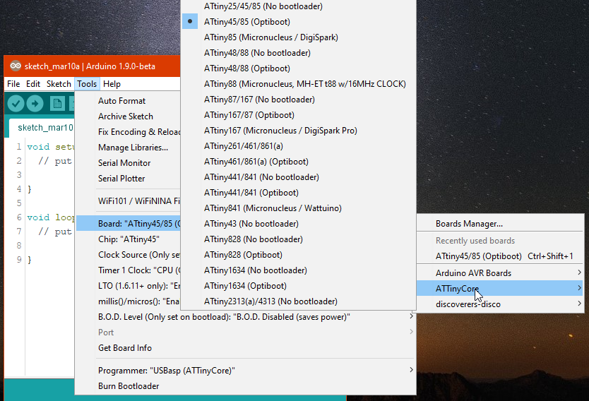
I’ve found an updated ATTinyCore for the ArduinoIDE. These Board-Definitions are compatible with actual ArduinoIDE version.
For installing the ‘Additional Boards Manager URLS’ is http://drazzy.com/package_drazzy.com_index.json
There are lot’s more ATTinys supported.
As mentioned in the Programming part of the github repository, the ATTiny should be programmable via an FTDI-Adapter, after flashing the ‘Optiboot’ Bootloader.
Should ! The Hello-Board would need a little redesign, connecting the DTR Pin from the FTDI Pinheader through an 0.1uF ‘autoreset’ capacitor, to the RST Pin of the ATTiny.
In my Board-Design it’s missing, so flashing over FTDI doesn’t work.