III. Design rules and drawing a mold
design rules
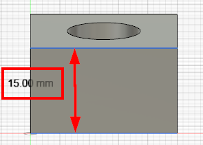
For the test cast I decided to make a negative from my Testcube
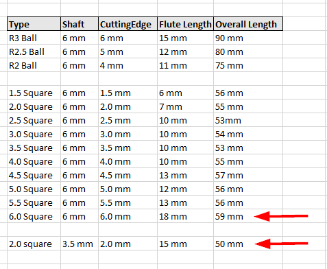
Before designing a mold, it’s necessary to think about the design rules and which mill-bits are available for the machine which should be used.
For our Roland-MDX 50 we have the following bits on stock
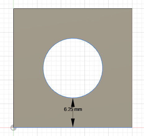
This is the cube, which I would like to cast
I can mill the mold with the last two end-mills, marked in the screenshot.
The 6mm square bit can pass the outer line and the inner circle and the ‘flute length’ of the bit is long enough to reach the ground, so I can use it for rough cut.
The 2mm square is the finest one we have. The ‘flute length’ is also long enough, so I’ll use it for the finish cut.
Of course, because of the 2mm square bit, it’s NOT possible to mill 90 degree inner edges. So the cube will have rounded corners !
But for this test cast it’s okay.
designing a negative mold
In Fusion360 I draw the cube as described in the Computer aided design section.
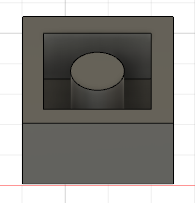
Additionally I draw a bigger cube beside the testcube
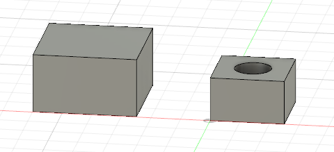
I moved the testcube inside the bigger cube

And used the cut function to cut the testcube out.
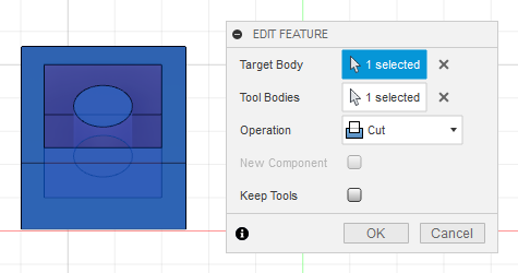
That’s it
The mold has to be exported as stl file.
designing a positive mold
For milling a positive mold, it would be also possible to just load the stl file into the SRP-Player software.
Alternatively we can design the mold in Fusion360.
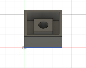
With the same design rules as above, I draw a sketch
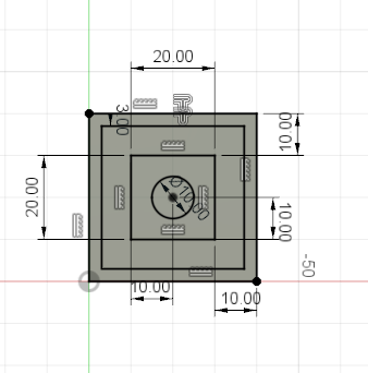
And extrude it to a mold
The archive with the fusion360 and the exported stl files are available HERE