II. Using Fusion 360
For CAD (computer-aided design) I choose Fusion360
Fusion 360 is a commercial software, but it is free for personal and education use !
In Fusion 360 there are different ways to create a 3D Model. I’ll show you two of them here.
To change the “camera view”, you can rotate the cube, placed in the top right corner:

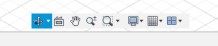
or use the icons from the “view bar” down in the middle
In this both examples, I show you how to create a simple box with a hole in the middle, in different ways.
1. create and modify a volume body directly
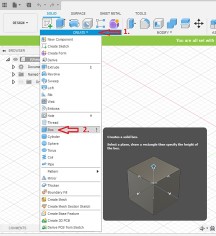
Just click on “create” and choose “box”
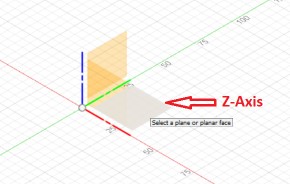
Then you have to select the axis, where you would like to put your box.
We choose Z-Axis, because we would like to build it up high.
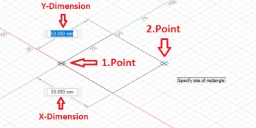
In the next screen, we have to select our Startpoint (1.Point) and the Endpoint (2.Point)
It is also possible to enter the values of the x/y dimensions directly.
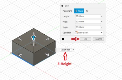
For our example, we choose a size of 50 x 50 mm.
In the next step, we can define the Z-Height, by “drag&drop” the blue arrow or entering the value (here 25mm) directly.
Confirm the made changes by clicking the “ok” button.
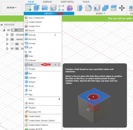
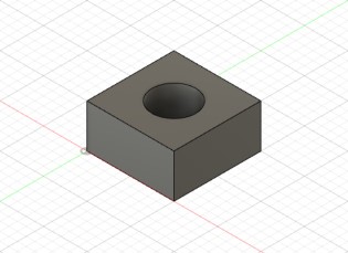
Here we have our box and now we would like to drill a hole with a diameter of 25mm inside it.
For this, we have to click “Create” and then “Hole”:
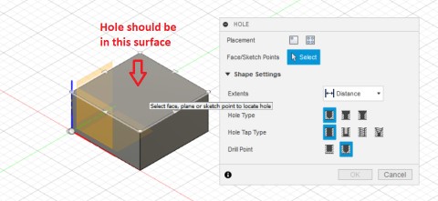
Now we have to select the surface, where the hole should be placed:
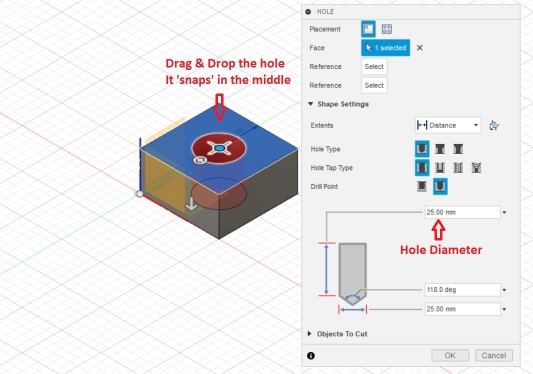
Our hole should be in the middle of the surface. So we have to “drag&drop” the hole.
Sounds funny, but that’s the way it works.
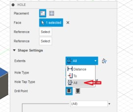
As hole diameter, we choose 25mm
At “Shape Settings” - “Extends” we change the option to “All” and confirm with “ok”
It means, that the hole goes through the hole object.
Aaaaaand....there it is :
The other way is :
2. Create a volume body with a technical drawing.
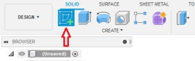
First we have to create a new sketch
Then we have to select the axis, where we would like to put our box.
We choose Z-Axis, because we would like to build it up high.
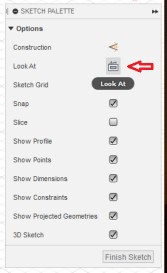
a box will open on the right side. There we can change the camera view.
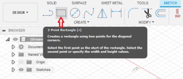
Now we draw a 2-Point Rectangle…
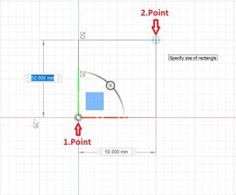
In the next screen, we have to select our start point (1.Point) and the Endpoint (2.Point)
It is also possible to enter the values of the x/y dimensions directly.
For our example, we choose a size of 50 x 50 mm.
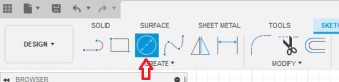
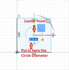
Then we draw a circle in the middle of the Rectangle with a diameter of 25mm
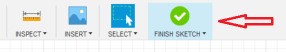
When this is done, we have to “finish” the sketch
now, we use the “extrude” function.
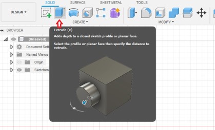
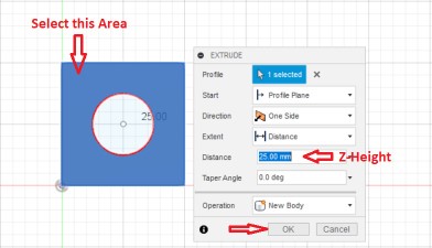
we have to select the surface, which we want to extrude
There is also box opened. Here we can set the extruding distance (Z-Height).
Here we set the distance to 25mm and confirm this selection with “ok”
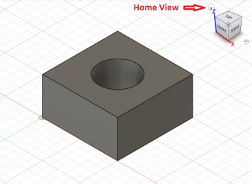
Et voila....finished !
The Fusion360 Testcube can be downloaded here
and the exported stl file can be downloaded here
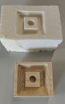
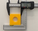
I personally use a smaller version of this cube, for 3D-Printer Calibration or for fast testing a CNC-Mill
During the weeks, I used Fusion360 in the following assignments:
In week 03. Computer-controlled cutting, I did a parametrical design
In my 05. 3D Scanning and Printing week, I also explained, how to export a stl file
Also in week 07. Computer-controlled machining and 11. Molding and Casting
And I did the case for my final project with Fusion360