I. Overview
In this week we have to Propose a final project masterpiece that integrates the range of units covered, answering:
What will it do?
My final project is a numeric display with 6 original ZM1040 Nixie Tubes from the 70s.
The main functionality is to display the time, but more functions are conceivable and optional.
Who’s done what beforehand?
There are some open source, but also commercial Nixie Clocks available in the web.
A good documented Nixie-Clock project is available at instructables
What will you design?
I’ll design a digital clock like object, what is decorative and looks nice E.g. in the living room.
That includes the hole electronics and the case.
What materials and components will be used?
2mm Acrylic Sheet, Sticker foil and MDf wood for the case. I got these from the local DIY market.
Some PLA for 3d print the pcb mounts. I use redline filament
2x PCB boards from Amazon with the following main parts:
- 6 ZM1040 Nixie Tubes from fablab stock, but also available at ebay
- 6 K155id1 driver IC available at ebay
- 4 IN-3 Nixie Dots (optional) from ebay
- 1 DS1307 RTC Module from AliExpress
- 1 12V Power Supply Amazon
- some miscellaneous electronic parts from reichelt
A complete BOM is available on my final project documentation page
Where will come from?
See above
How much will they cost?
| Case Parts | ~ 30 EUR |
| PCB Boards | ~ 15 EUR |
| Nixie Tubes | ~ 300 EUR |
| K155id1 | ~ 10 EUR |
| IN-3 Dots | ~ 7 EUR |
| RTC Module | ~ 1 EUR |
| Power Supply | ~ 10 EUR |
| misc electr. | ~ 25 EUR |
| -------------- | ----------- |
| Summary | ~ 398 EUR |
What parts and systems will be made?
- an ATmega328 based controller board
- a separated PCB for the Tubes
- 2 wooden side panels for the case
- a flex-cut acrylic case cover
- sticker decoration for the inside of the case cover
- 3D printed PCB holders
What processes will be used?
- PCB milling and soldering
- 3D printing
- 3D milling
- Lasercutting
- Vinylcutting
What questions need to be answered?
- What could be a good and practicable alternative, getting the time ?
- What about daylight saving times ?
- How can I build a flux capacitor for optional time-traveling ?
How will it be evaluated?
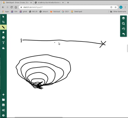
With beginning of the second class, Niel told us the difference about serial vs spiral tasks/development a view times during the FabAcademy cycle.
First sketch from 27.01.2021
And the last one from 02.06.2021 :-D
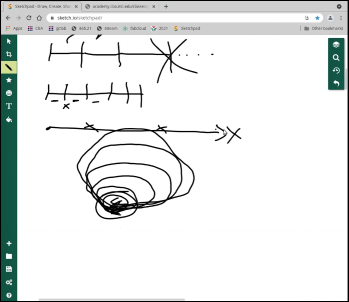
Spiral development is exactly what I did and what I already had in my mind, before the academy has started.
These are my spirals I worked with
- Prototyping the bare minimum of electronics on a breadboard. That has included an Arduino Nano, 3x Shiftregister and 24 LEDs to see how Shiftregister works and if it’s possible to ‘address’ the K155id1 decoder chip.
- Testing the K155id1 decoder chip on a breadboard with an Arduino Nano and 10 LEDs to simulate a Nixie Tube
- Merge Spiral 1 and 2 together. Prototyping now has included the Arduino Nano, 3x Shiftregister, 6x K155id1 decoder chip and 60 LEDs to simulate 6x Tubes
- Testing different ways catching the time to see what works and what is unpracticable.
- DS1307 - okay but not perfect
- DCF-77 module - not usable, very sensitive against electromagnetically noise
- NEO-6M GPS module - not optimal, needs good indoor positioning
- Building an output device with just one Tube to see, if I’m able to firing up and address a Tube.
- Building the electronics with everything is needed, for just firing up the 6 Tubes, but with optional pads to add more functions. Just programmed a sketch which counts the numbers Tube by Tube.
- Adding the DS1307 RTC Module and FTDI-Pinheader to the board and programming the clock sketch.
- RTC works, FTDI NOT ! But that’s no deal breaker, development can go ahead.
- Added 4x animated dots
- Building the Case
- Finishing the project with it’s presentation