shift register
wiring
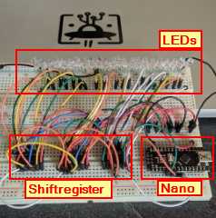
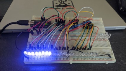
To try out how shift register work, I used an Arduino Nano, placed on a protoboard.
I’ve put 3x 74HC595 shift register on the board and 24 LEDs. I’ve used the 3V3 Line on the Arduino Nano, so no resistors are needed for the LEDs.
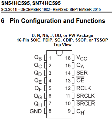
In the datasheet is a pinout diagram of the chip.
The following sheet, shows how the chips are connected to the Arduino and the anodes(+) of each LEDs. The cathodes(-) are all connected to ground (GND). Only the first 74HC595 has to be connected to the arduino.
| connected to | 74HC595 | 74HC595 | connected to |
|---|---|---|---|
| LED (2) | 1 - Qb | VCC - 16 | 3V3 |
| LED (3) | 2 - Qc | Qa - 15 | LED (1) |
| LED (4) | 3 - Qd | SER - 14 | Arduino D2 |
| LED (5) | 4 - Qe | OE - 13 | GND |
| LED (6) | 5 - Qf | RCLK - 12 | Arduino D4 |
| LED (7) | 6 - Qg | SRCLK - 11 | Arduino D3 |
| LED (8) | 7 - Qh | SRCLR - 10 | 3V3 |
| GND | 8 - GND | Qh’ - 9 | SR (2) Pin 14 |
To put the shift registers in serial I used this wiring
| 1st SR -> | 2nd SR -> | 3rd SR -> |
|---|---|---|
| PIN 12 | PIN 12 | PIN 12 |
| PIN 11 | PIN 11 | PIN 11 |
| PIN 9 | PIN 14 | -------- |
| -------- | PIN 9 | PIN 14 |
The rest is as above. The LEDs are counting that way until the 24th.
programming
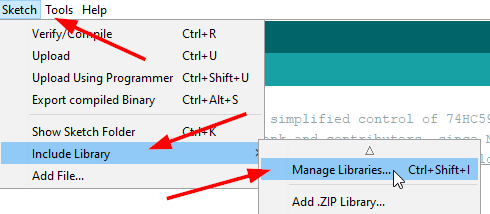
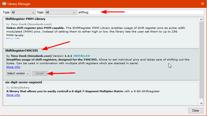
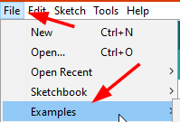
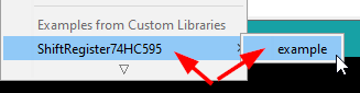
In the Arduino IDE I’ve added the ShiftRegister74HC595 library
Then I’v loaded the shiftregister example sketch
And adapted it by
- changing the variable
numberOfShiftRegistersto3 - changed the
pinsettings to avoid problems in serial communication - removing
all pins highat the begin of the loop - adapting the two
FOR loopsthat all 24 LEDs will light up - removing everything after the two
FOR loops
In the “original” example, the pins are set to 0, 1, 2, but 0 and 1 are used for serial communication.
In the ongoing project, I’ll maybe use serial communication for debugging. That’s the reason, why I changed the pin settings to 2, 3, 4
I’ve added a new FOR-Loop for counting backwards, so I’ve a running light.
Here is the sketch I used. I set remarks, in capitals, on the corresponding lines
/*
  ShiftRegister74HC595 - Library for simplified control of 74HC595 shift registers.
  Developed and maintained by Timo Denk and contributers, since Nov 2014.
  Additional information is available at https://timodenk.com/blog/shift-register-arduino-library/
  Released into the public domain.
*/

#include <ShiftRegister74HC595.h>

// create a global shift register object
// parameters: <number of shift registers> (data pin, clock pin, latch pin)

const int numberOfShiftRegisters = 3;   // CHANGED THE NUMBERS OF SHIFTREGISTER
int serialDataPin = 2; // DS            // CHANGED DS PIN
int clockPin = 3;      // SHCP          // CHANGED SHCP PIN
int latchPin = 4;      // STCP          // CHANGED STCP PIN
ShiftRegister74HC595<numberOfShiftRegisters> sr(serialDataPin, clockPin, latchPin);

void setup() {
}

void loop() {

/*          NOT NEEDED

 setting all pins at the same time to either HIGH or LOW
  sr.setAllHigh(); // set all pins HIGH
  delay(500);
*/

  sr.setAllLow(); // set all pins LOW
  delay(50);


  // setting single pins
  for (int i = 0; i < 8*numberOfShiftRegisters; i++) {      // I HAVE ADAPTED THIS FORMULA

    sr.set(i, HIGH); // set single pin HIGH
    delay(50);   // DECREASED THE DELAY
  }

  for (int i = 8*numberOfShiftRegisters; i > 0 ; i--) {     // ADDED A NEW LOOP FOR COUNTING BACKWARDS

    sr.set(i, LOW); // set single pin LOW
    delay(50);
  }


/*  FOLLOWING CODE IS NOT NEEDED IN MY TESTING ENVIRONMENT


  // set all pins at once
  uint8_t pinValues[] = { B10101010 };
  sr.setAll(pinValues);
  delay(1000);


  // read pin (zero based, i.e. 6th pin)
  uint8_t stateOfPin5 = sr.get(5);
  sr.set(6, stateOfPin5);


  // set pins without immediate update
  sr.setNoUpdate(0, HIGH);
  sr.setNoUpdate(1, LOW);
  // at this point of time, pin 0 and 1 did not change yet
  sr.updateRegisters(); // update the pins to the set values
*/
}
testing
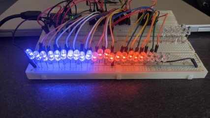
works !