III. Using FreeCAD
Here, I show you, how to create the Test-Cube by using the open-source parametric 3D modeler FreeCAD
If you would like to support the project, you can join the FreeCAD github or you can also make a donation
So, let’s have a look, how FreeCAD works…
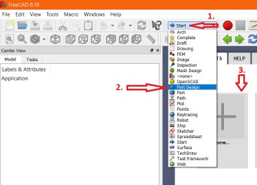
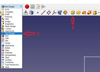
FreeCAD has different “Workbenches”
First, we have to click in the “workbench selection” and choose “Part Design”
and finally, we have to click “Create new”
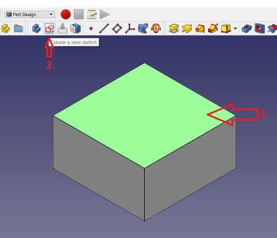
To change the “camera view”, you can click on the cube, placed in the top right corner:

or use the “view”-icons in the Toolbar

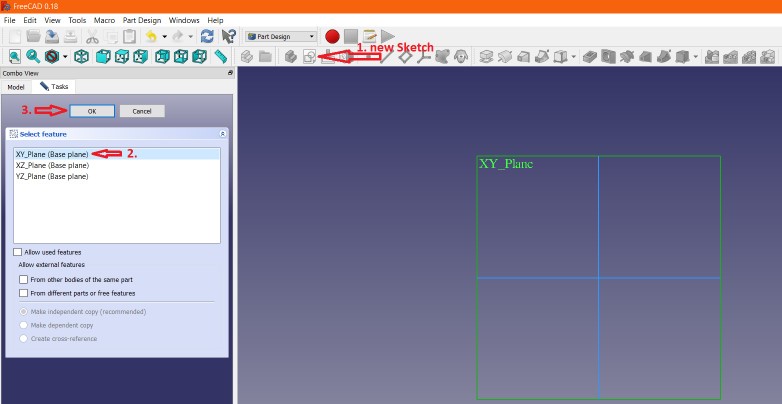
Then we have to create a new sketch by clicking the icon. A new “selection” window appears on the left side.
There we have to choose the axis, where we would like to draw the sketch.
Here we are drawing in the “XY_Plane” and confirm that by clicking “OK”
And as you can see, the “workbench” has also changed automatically to “Sketcher”
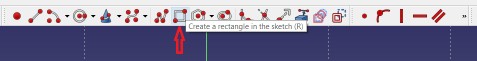
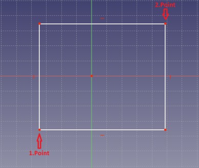
We start sketching with a 2-Point-Rectangle.
We have to select our Startpoint (1.Point) and the Endpoint (2.Point)
It’s not necessary to define a specific dimension. We’ll do it later.
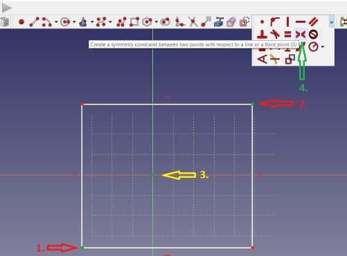
Now we define a “symmetry constraint” between the to points from the rectangle and the middle point.
For that, we have to click the points in the sequence as shown in the picture.
The points are turning “green” after clicking them.
To finish the process, we have to click the corresponding icon.
This means, when we now try to scale the rectangle (do it! ;-), the “center point” is always in the middle!
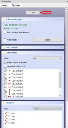
Time to add some measurements for the horizontal (x) and vertical (y) size of our rectangle.
The picture shows the two icons we will need.
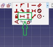
We can start by clicking the icon for the horizontal line and then select the (top) horizontal line of our rectangle.
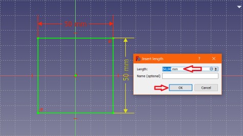
A box appears, where we can enter now the dimension of the horizontal line.
In our example, we enter 50 mm.
After doing the same, with the vertical line, it should be look like this :
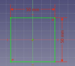
We can finish now our sketch by clicking “close” on the left side
The “workbench” should automatically switch back to “Part Design”
To extrude the rectangle, we click the icon “Pad a selected sketch”
In the box we change the “Type” to “Dimension” and enter 25 mm as length (Z-Height)
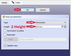
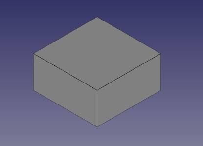
The box is finished. You can change the camera view to see the result
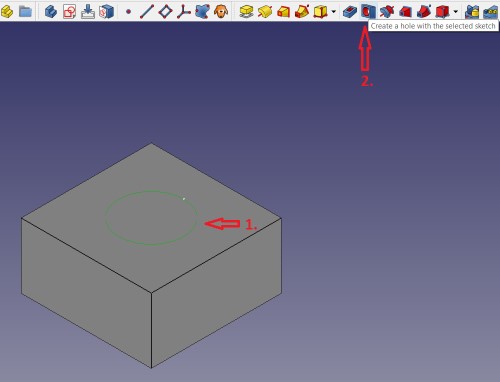
To make a hole in the cube, we have to select the surface, where the hole should be inside and
draw a another sketch there
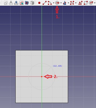
We’ll draw a circle in the sketch by clicking the corresponding icon, select the center point and drag the circle.
The dimension doesn’t matter. We add a measuring in the next step.
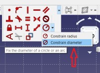
Add a constrain diameter
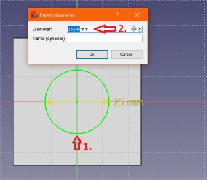
And enter 25 mm, because we would like to “drill” a hole with a diameter of 25mm.
After finish, confirm editing the sketch by clicking “close” on the left side.
Now select the circle (it turns green) and click the “create a hole” button
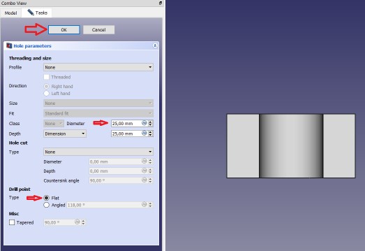
On the left side, we can enter now our hole dimension of 25mm and as drill type, we choose “flat”
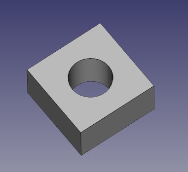
and confirm this with “ok”. I changed the camera view in the picture, to show you, how the hole is drilled.
Tadaaaa......finish !
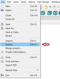
To export the cube as a printable stl file, select the “Model”-Tab on the left side and select “Body”
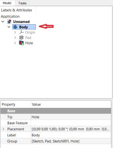
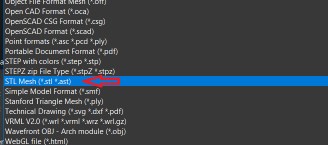
In the menu-bar, click “export”, select as “File-Type” “STL Mesh” and save it wherever you want :D
The FreeCAD Testcube can be downloaded here
and the exported stl file can be downloaded here
I think, I prefer still Fusion 360. It feels more comfortable and looks more modern.
But who knows, maybe I will switch to FreeCAD in the future.