III. building up a serial network
For this assignment, I’ll use my previous made boards.
These are the
- echo hello-world board from the ‘Electronics design’ week
- TCRT5000 Sensor Board from the ‘Input devices’ week
- Nixie Tube output device (Controller Board) from the ‘Output devices’ week
The echo hello-world board and the Nixie Tube controller board have an onboard LED, each. I would like to use the TCRT5000 (distance) Sensor Board as an input device and the the LED’s, from the other boards, as a warning signal notification.
To do so, I would like to build a serial network and make a connection with the serial FTDI header, from each board.
My idea is to light up, depending on the distance, first one LED, then both LEDs and finally both LEDs should alternately flashing.
Each LED board will get a node id which I’ll be able to address them and with an additional information (1 or 0), I would like to turn the LED on or off.
A message could be just a 21 what means: node 2 LED ON or E.g. a 10 what means: node 1 LED OFF
Testing a serial communication
First, I just connected the echo hello-world board and made some easy serial tests like in my embedded programming week.
I used the example code from the arduino Serial.read() reference page and adapted it to my hello-world board, for an easy send / response test.
I tried just typing 21 in the serial monitor and got this response :
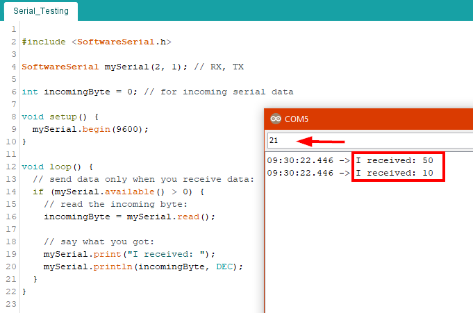
The microcontroller reads the input data as ASCII characters, so that’s the reason for this strange output. In the ASCII Table you can see, that the character 2 has a value of 50 and the line feed is 10
the character 1 was dropped completely. That’s nothing I can work with!
In Adrián Torres Servo Bridge code, I’ve found the crucial clue.
Instead of mySerial.read() I have to use mySerial.parseInt()
So next try…
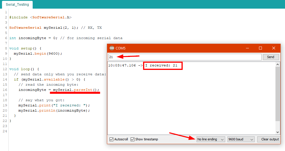
Much better. In the serial monitor I changed the line feed to No line ending so I got the response, I was expecting.
But there was another problem ! When I typed the numbers to fast, the controller red this as one big number:
10:19:21.611 -> I received: 1112
10:19:24.831 -> I received: 11
10:19:26.158 -> I received: 12
10:19:32.195 -> I received: 1011
On the arduino reference page about serial I found the command setTimeout().
After implementing mySerial.setTimeout(100) in my code, I was able to write the numbers fast.
I’ve also implemented a variable called node_id. With this, I’m able to define a logic, that the board can be addressed.
programming the nodes
node 1 - echo hello-world board
The sketch now looks like this :
#include <SoftwareSerial.h>

SoftwareSerial mySerial(2, 1); // RX, TX

int node_id  = 1; // node id
int ledPin   = 3; // LED pin number
int incoming = 0; // for incoming serial data

void setup() {
  mySerial.begin(9600);
  mySerial.setTimeout(100);  // Set Timout for separated numbers
  pinMode(ledPin, OUTPUT);
}

void loop() {
  // check if data is available
  if (mySerial.available() > 0) {
    // read the incoming data
    incoming = mySerial.parseInt();

  // say what you got for debugging
  //    mySerial.print("I received: ");
  //    mySerial.println(incoming);
  }

  // check if incoming data is for me
  // if so and data ends with '1' turn LED ON, when data ends with '0' turn LED OFF
  if (incoming == node_id * 10 + 1) {
    // turn LED on:
    digitalWrite(ledPin, HIGH);

  } else if (incoming == node_id * 10){
    // turn LED off:
    digitalWrite(ledPin, LOW);
  }
}
With defining the node_id to 1 I can now send :
10 for Node: 1 - LED OFF and
11 for Node: 1 - LED ON
node 2 - Nixie Output Controller Board
The pin mapping is different, compared to echo hello-world board, so I had to adapt the setup part of the code AND I have the special case with the LEDs ground, which is connected to digital port 10, so I have to define that port as low
This is now the header :
#include <SoftwareSerial.h>

SoftwareSerial mySerial(7, 8); // RX, TX

int node_id  =  2; // node id
int ledPin   =  9; // LED pin number
int ledGND   = 10; // For OutputDevice only, LED cathode is connected to D10
int incoming =  0; // for incoming serial data

void setup() {
  mySerial.begin(9600);
  mySerial.setTimeout(100);  // Set Timout for separated numbers
  pinMode(ledPin, OUTPUT);
  pinMode(ledGND, OUTPUT);
  digitalWrite(ledGND, LOW);
}
The main code is exactly the same as from node 1
With defining node_id = 2 I can now send :
20 for Node: 2 - LED OFF and
21 for Node: 2 - LED ON
The complete code is on the bottom of this page.
wiring up
The first thing I did, was to solder a FTDI ‘y-cable’ that I’ll be able to plug the three boards together. I cut female jumper wire
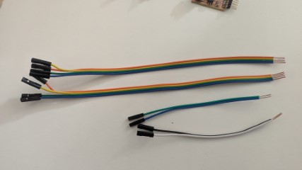
and soldered each line of them together
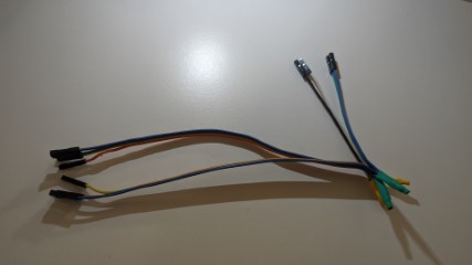
Now I have (for the VCC, GND, TX and RX line) 3 connectors, each.
Testing the nodes
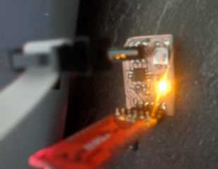
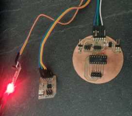
After connecting both nodes with an FTDI USB Adapter I opened a serial monitor and start sending a 11 what means node 1 - LED ON
The red LED is just the power LED from the FTDI Adapter.
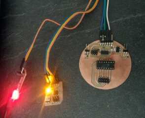
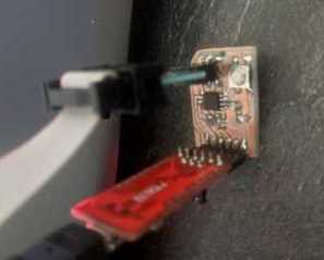
then sending a 10 and 21 what means node 1 - LED OFF and node 2 - LED ON
and finally again sending a 11
sensor data sending node
The sensor part of the sketch, is the same as in the input devices week.
In the header I defined a variable int wait = 150; This defines a short delay between sending the commands to the nodes. Because of the mySerial.setTimeout(100) within the nodes, the wait variable has to be bit more than 100, otherwise the nodes aren’t able to ‘decode’ the commands.
I defined the following logic:
If the sensor data is
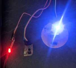
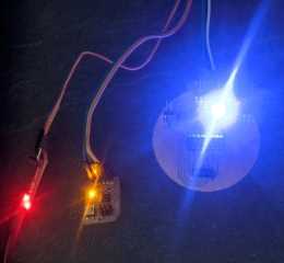
- below 200 : both LEDs off.
- between 205 and 450 : Node 1 - LED ON / Node 2 - LED OFF
- between 455 and 850 : Node 1 - LED ON / Node 2 - LED ON
- bigger 855 : both LEDs blinking alternately
Here is a code snippet:
if ( c >= 205 && c <= 450 ){
    mySerial.print("11");
    delay(wait);
    mySerial.print("20");
  }
The output now looks like this :

The complete code is also on the bottom of this page.
The Network
Now I’ve connected the sensor board (left) with both nodes
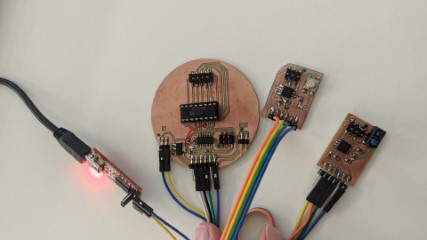
On the right side, you see a FTDI USB Adapter. I used this only as a 5V power source. So the VCC/GND from the FTDI USB Adapter are connected to the VIN/GND of the Nixie Controller Board.
On the sensor board the TX/RX pin have to be swapped. So the connection is now
| sensor | node 1 | node 2 |
|---|---|---|
| TX | RX | RX |
| RX | TX | TX |
| VCC | VCC | VCC |
| GND | GND | GND |
and now comes the exciting moment.......
GREAT
Need for Speed
After playing around with the setTimeout in the nodes and the wait value in the sensor, I was able to speedup the communication.
The maximum is now setTimeout(10) in the nodes and a delay from 15 in the sensor sketch.
The LEDs blinking so fast, that it’s hard to see in the video.
Here are the downloads: