III. Parametrical design with Fusion360
After a small chat with my colleague Aleksandra (industrial designer and graduate of the FabAcademy in 2017),
I’ve got the idea to enrich the living culture :-)
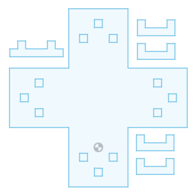
The main idea was, to create a customizable coaster for pots and jugs.
It should be expandable with the shape of a cross and little standing feet. The feet are also usable as connectors for the extensions.
The parts could be natural painted E.g. with curry or red beet.
For creating the parametrical construction kit, I used Fusion360.
I never did it before in that way, so I had to do a little research about that and found all necessary information’s, in an Autodesk tutorial.
Here is a quick tour, how I created the kit with Fusion360.
sketching the cross
First I started with sketching the cross with the line tool
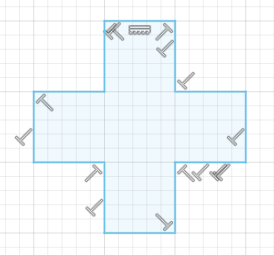
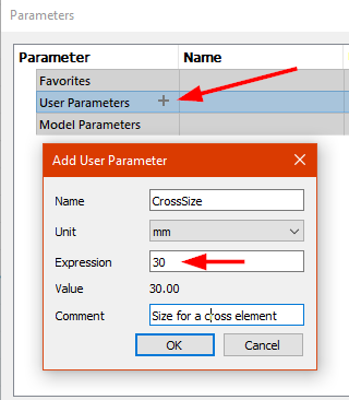
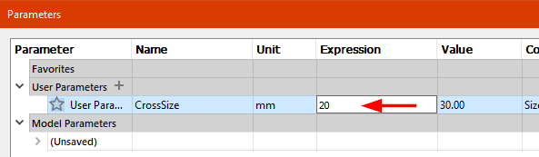
and added a user parameter. Each line of the cross should be 30mm long
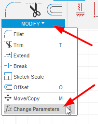
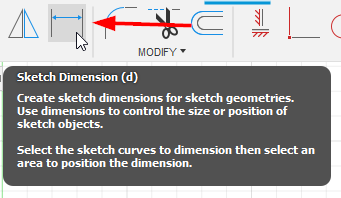
defining dimensions with user parameter
After that, I defined sketch dimensions for each line around the cross
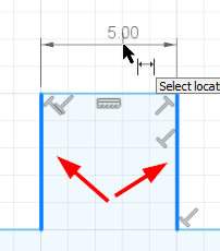
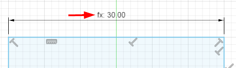
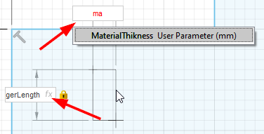
What I didn’t know yet, it’s possible to add a user parameter as dimension

With setting a user parameter, the dimension description looks a bit different and shows a little fx
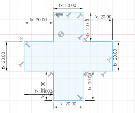
I did this around the hole cross

Now it’s possible to change the size of the cross by typing an other value in to the user parameters panel
adding more parameters and joints
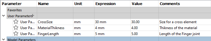
For the connectors I need two more parameters. The first one is the material thickness and the second one I called finger length
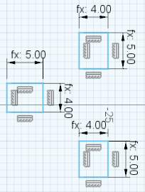
Now I draw three boxes with the two new parameters as dimensions
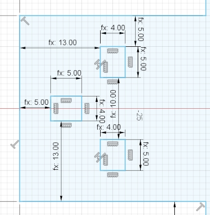
placing the joints by using formulas
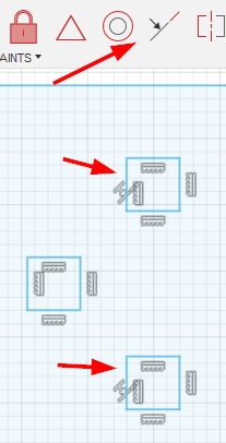
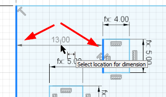
The three boxes have now to be placed, depending on the selected values
I added a Collinear Constrain on two boxes, that the vertical position, of these two, are fixed
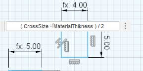
The boxes should now horizontally be in the middle. To do that, I added the little calculation ( CrossSize - MaterialThikness ) / 2 as dimension
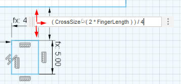
For vertical positioning I used the formula ( CrossSize - ( 2 * FingerLength ) ) / 4 between the marked lines
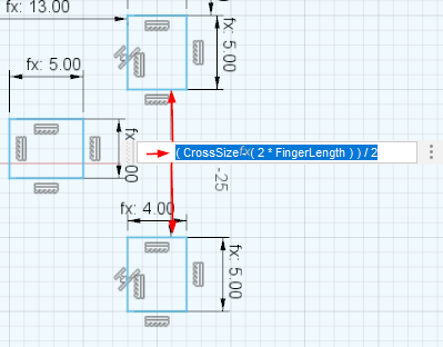
Now the lower box has to be ‘fixed’ with the formula ( CrossSize - ( 2 * FingerLength ) ) / 2
The box on the left is left. :-D I added the same formulas as above, but I’ve swapped them for the horizontal and vertical direction.
a litte test
Okay let’s try it…
We change the parameter to 50mm CrossSize - 5mm MaterialThikness - 8mm FingerLength and see what happens…
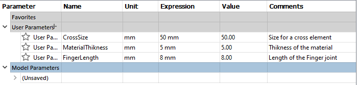
Cooool....it works !
Sadly I found no way, to copy & paste the complete part, with the dimensions included, so I had to draw and add it manually to the other three corners.
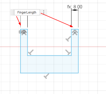
sketching the connectors
Sketching the connectors is the quite similar procedure.
I started drawing a U shape

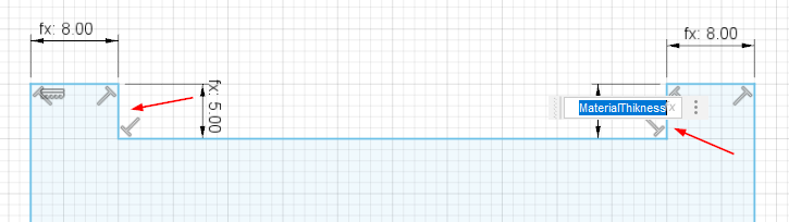
Added the FingerLength dimension
and the MaterialThikness
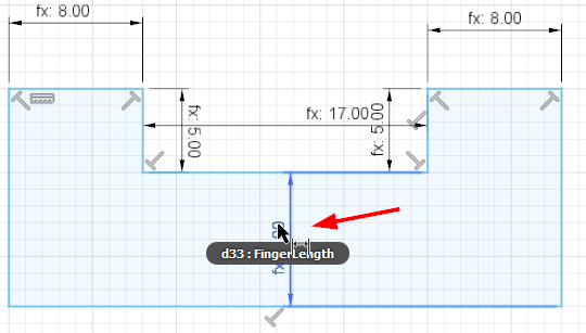
The distance between the finger-joints is again the formula ( CrossSize - ( 2 * FingerLength ) ) / 2
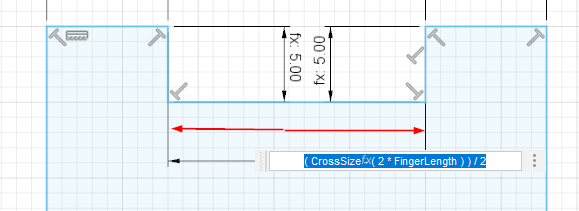
And there is a last one missing
Well done…!
I’m now able, to change the dimensions with only three variables :-)
The fusion360 file can be downloaded here
Does it work ? I don’t now, yet ! Will see it next days, during the lasercutting session…
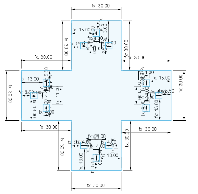
Corrections
As I inspected, the design doesn’t work as is. The sketch needed an additional parameter CuttingWidth
I changed some formulas and now it works perfect !
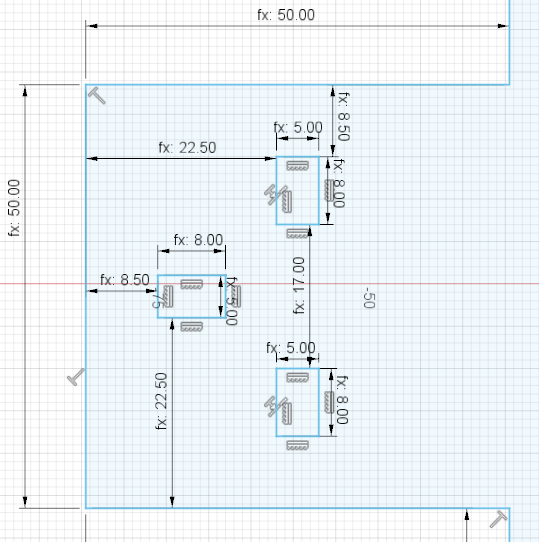
These is now the final parameter list:

An this is, how the the sketch now looks like. You can compare the values with the parameter, to see, which formula is on which place.
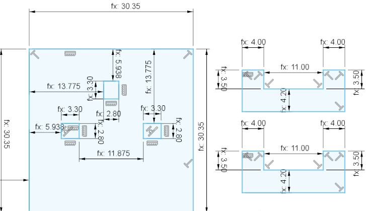
And this the corrected fusion360 file