II. Using test equipment
Multimeter
A very important measuring tool is a Multimeter. I used it e.g., for testing my Hello-World Board, after milling. With the “beeper” function, I can test and investigate the milled board for short-circuits.
In my short video, I show you the measuring of a PWM Signal of the Arduino.
I flashed the ‘fading example’ sketch on an Arduino Nano and connected an LED with it’s resistor on the digital Pin 9.
Oscilloscope
For this assignment I used a cheap DSO138 DIY Oscilloscope.
I assembled this kit long time ago and never used it, till now.
The orange case is 3d printed. I found the files on thingiverse
A very good quick tutorial is available at foxbotindustries.com
The Oscilloscope show me e.g., the Min/Max Voltage and visualize the timing between the 5V pulses.
I used the following settings for my measuring:
- Top Switch (CPL) to
DC: because I would like to measure the DC Voltage
The next two buttons are for zoom in and out. I used these settings for a good visualization :
- Middle Switch (SEN1) to
0.1V - Bottom Switch (SEN2) to
X1
With the SEL Button on the bottom right side, it’s possible to jump between additional settings.
There I changed the Time to 0.5ms
And here I show you the output from my cheap DSO138 DIY Oscilloscope
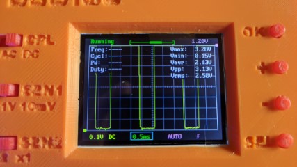
The measured values are:
Vmax: 3.28V
Vmin: 0.15V
Vavr: 2.13V
Vpp : 3.13V
Vrms: 2.58V
And here is the visualization