V. Milling and soldering
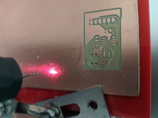
Here are some pictures of the milling process (old pcb layout), separated into the individually generated FlatCAM files…
The milling procedure is described in the Electronics Production week.
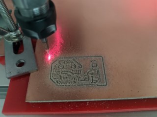
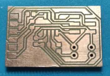
1_Isolation-04mm_2-passes.nc
With my new 0.4mm end-mill, it looks really nice now.

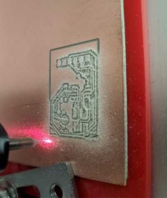
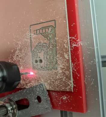
2_CopperRemoval-04mm.nc
3_Drill-1mm.nc
Here I changed the 0.4mm end-mill to a 1mm drill bit
4_NPTH-Drill-1mm.nc and 5_NPTH-Drill-2.5mm.nc
I changed the tool to a 2.5mm drill bit for these holes. The holes are not deep enough. I’ve to adjust it’s settings in the future.
6_Cutout-Mill-1mm.nc
Sadly I’ve forgotten to make pictures of the cutout milling process. I did the cut out with an 1mm end-mill.
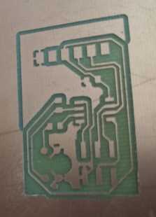
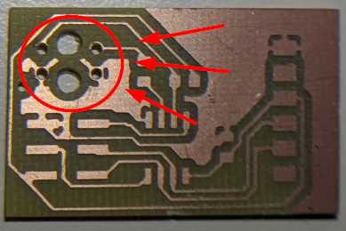
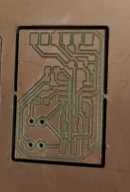
finished board
This is the finished board. The solder pads for the TCRT5000 are much to small. I adjusted the footprint as described in the KiCad section.
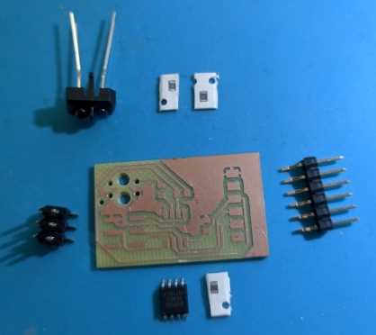
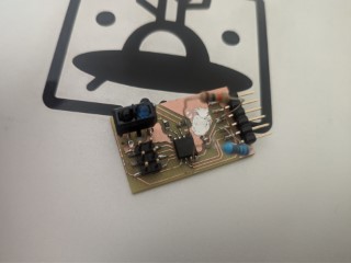
soldering
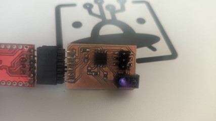
Here is the board with it’s components.
I’ve forgotten to sand the board, before soldering. That gave me really bad joints !
However, I have to redo the board again anyway, because of the missing resistors as described in the KiCad section.
I made a ‘frankenstein’ and placed the missing resistor on top.
the new board
This is now the new board
The soldered components have a much better joint AND it works now !