characterize your lasercutters focus, power, speed, rate, kerf, and joint clearance
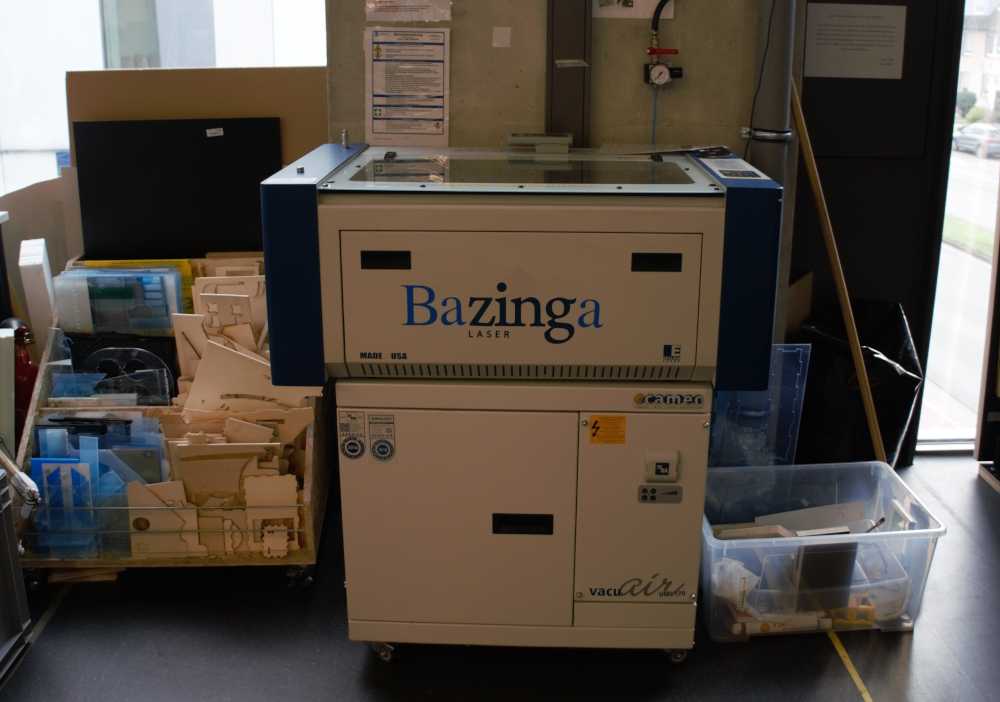
Our Laiser is from the company Zing igendwer has expanded with the company name by Bazinga.
stainless steel; laminate based plastics; acrylic/plexiglass; painted metals; anodised aluminium; wood, plywood, MDF and veneer; glass; stone, granite and marble; ceramics and tiles; leather; rubber; paper, cardboard and paperboard; cork; fabrics and textiles; earmoulds; biogravure: e.g. sausage or apple
Laminate based plastics; acrylic/plexiglass; wood, plywood, MDF and veneer; paper, cardboard and paperboard; cork; foil; leather; rubber; fabrics and textiles
| workspace | 610 x 305 mm |
|---|---|
| engraving speed | 14,45 min |
| resolution | 150 dpi - 1000 dpi |
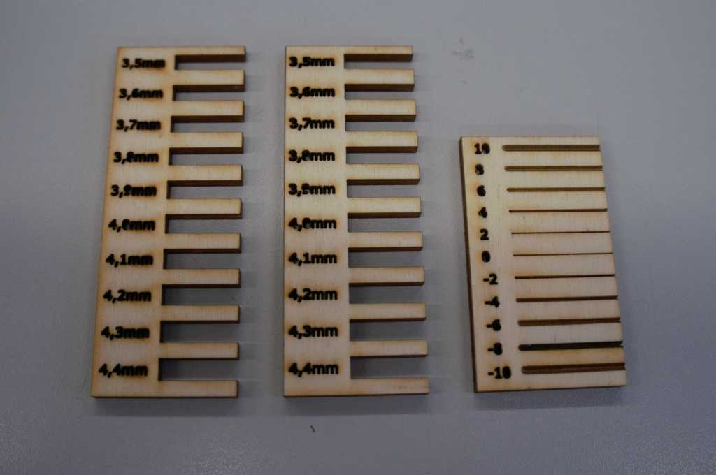
I cut the pictured objects to figure out the characteristics of our lasercutter.
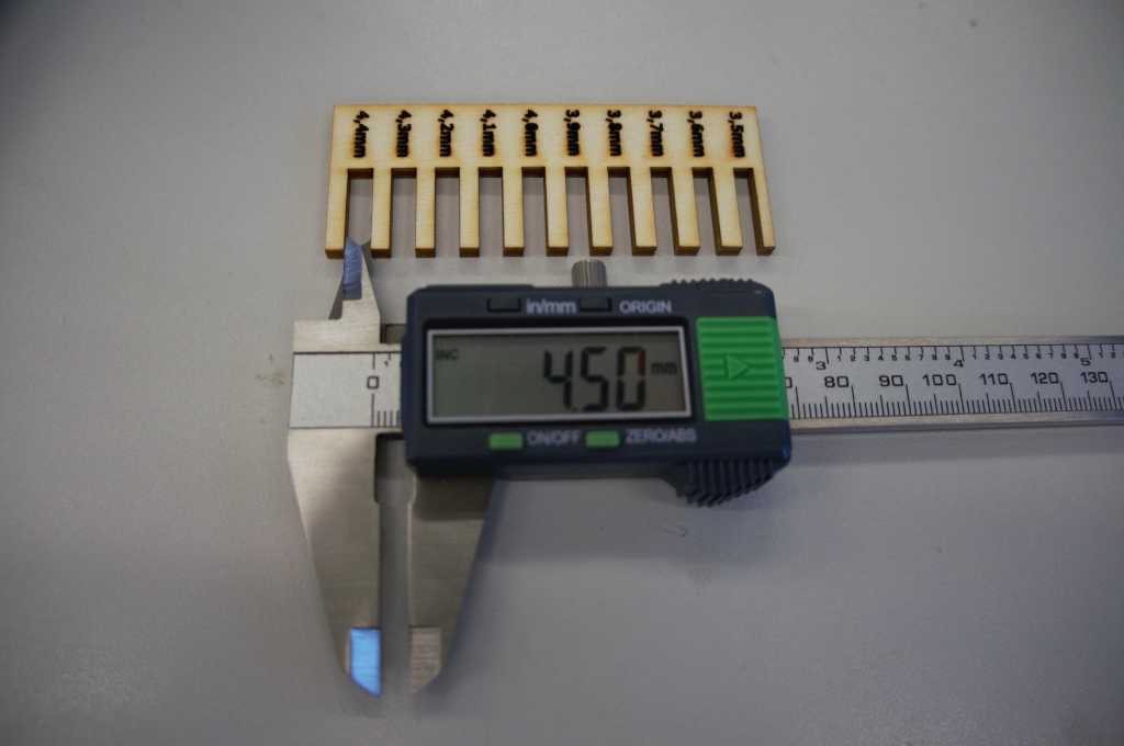
Here you can see that the lasercutter, similar to a saw, removes material from between the two pieces it's cutting. Therefore we have a gap of 4.5mm at a set distance of 4.4.mm
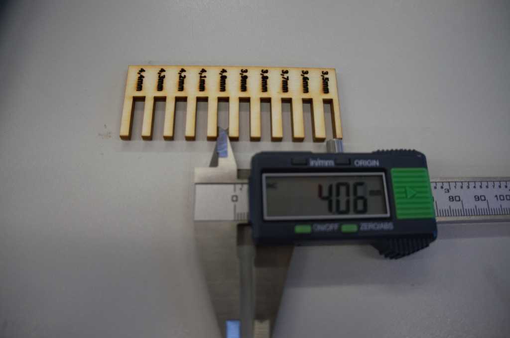
Same as before. Set distance: 4.0mm, actual distance: 4.06mm.
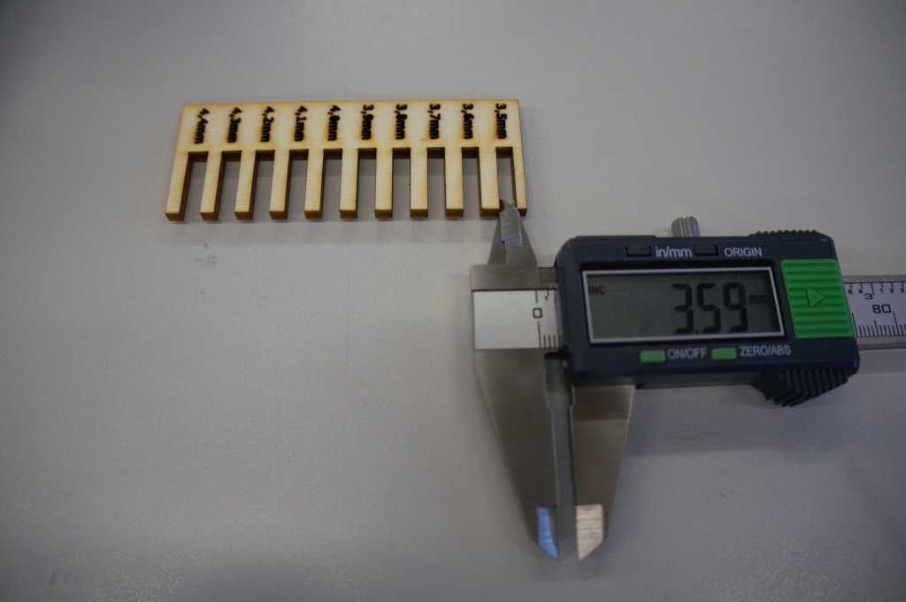
Same as before. Set distance: 3.5mm, actual distance: 3.59mm.
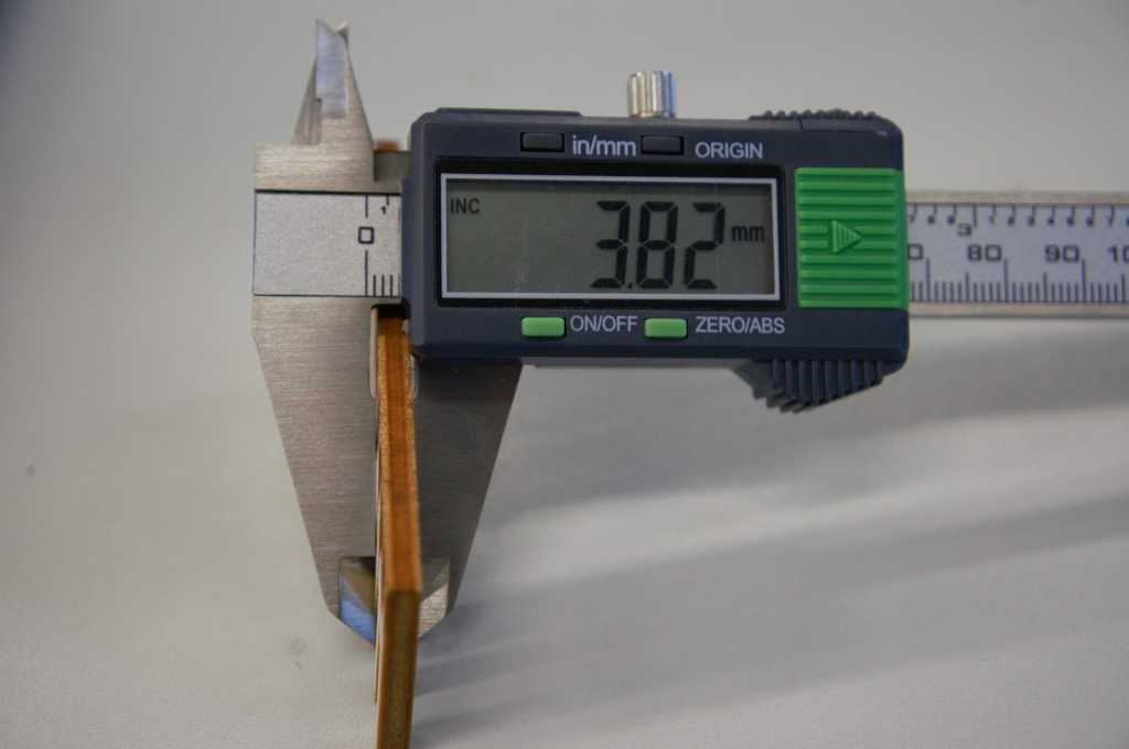
The used plates of wood are 3.82 mm thick.
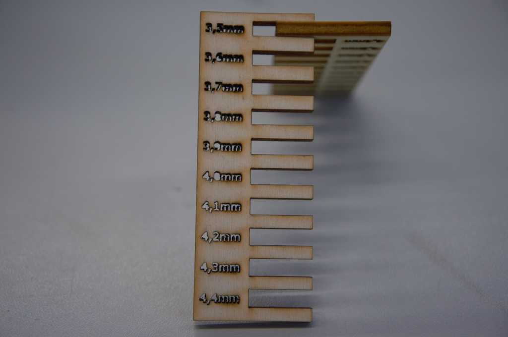
First I tried it with a gap that is 3.5 mm wide but the wood it did not fit.
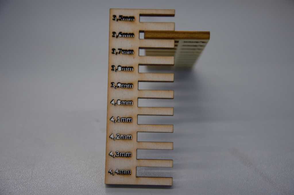
Next I tried the gap with 3.6 mm and it did not fit here either.
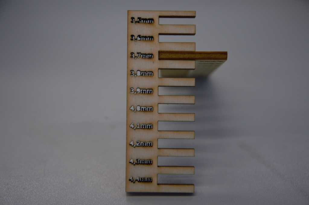
The gap of 3.7 mm fit.
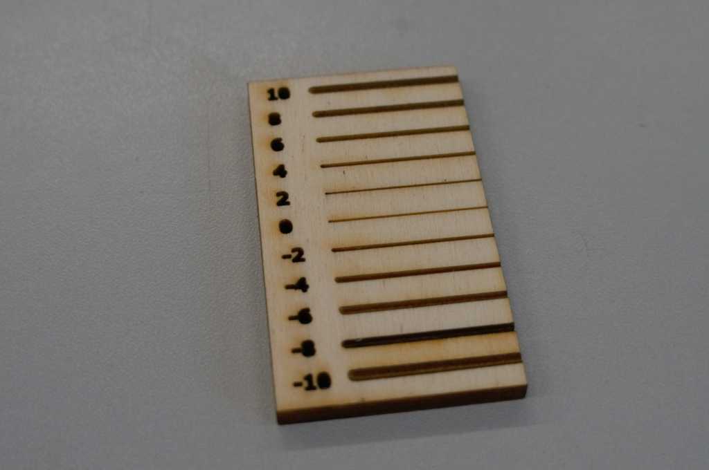
I experiemented with the focus of the lasercutter. You can see if the focus is not adjusted correctly. The further away the focus is from the actual value, the more conical the notch is.
To show further possibilities of using the lasercutter I
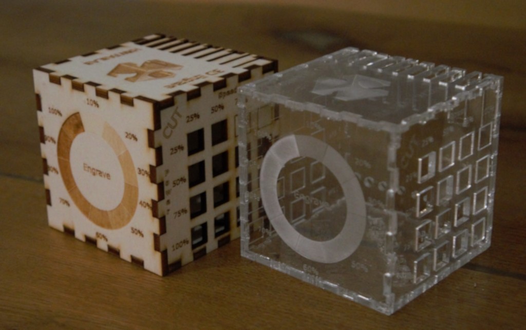
designed a cube on whose outside you can see different examples of our lasercutter.
I created the box with makerCase.
The sides contain:
- Setting for Mark
- Setting for Cut
- Difference Mark-Cut-Engrave
- Settings for engrave
- Setting for 3D engrave
- Joint spacing
I cut one out in acrylic as well as in wood, as you can see in the video below.
I glued the dice together because they are on our exhibition table and go through a lot of hands.
They would also hold together but when they do they are more stable when they fall on the floor or something.
Download box for 3 mm
Material
Lasercutter values.
Acryl cut
| 25% | 50% | 75% | 100% | |
|---|---|---|---|---|
| 25% |
|
|
|
|
| 50% |
|
|
|
|
| 75% |
|
|
|
|
| 100% |
|
|
|
|
Acryl Engrave
| 25% | 50% | 75% | 100% | |
|---|---|---|---|---|
| 3% |
|
|
|
|
| 6% |
|
|
|
|
| 9% |
|
|
|
|
| 12% |
|
|
|
|
Wood cut
| 25% | 50% | 75% | 100% | |
|---|---|---|---|---|
| 25% |
|
|
|
|
| 50% |
|
|
|
|
| 75% |
|
|
|
|
| 100% |
|
|
|
|
Wood Engrave
| 25% | 50% | 75% | 100% | |
|---|---|---|---|---|
| 3% |
|
|
|
|
| 6% |
|
|
|
|
| 9% |
|
|
|
|
| 12% |
|
|
|
|
With parametric design, the parameters such as length, angle, etc. are defined as variables and can therefore be changed later. As soon as you give a size a fixed value it is fixed. For example, if you assign an angle of 90 degrees to one of the two lines and change the length of one of the lines, the other line will move with it, because the angle has been set before. So you have to take care not to set too many parameters and make it impossible to change things later. The advantage of the paramtric design is that you can quickly make improvements later on. For example, if you have to change your screw holes so that they are a millimeter larger, you can make them dependent on each other so that you only have to correct one of them and they all change automatically.
cut something on the vinylcutter
I start with a new sketch.
First of all I add text by clicking on the big A in the left menubar.
I add a picture that I would like to have.
Then I select the area of the picture that I want for tracing.
Now I can send the file with a press on a button in the top right corner to the plotter. Since it is supposed to be added to a piece of cloth, the text has to be mirrored.
I set the material to thermal transfer foil.
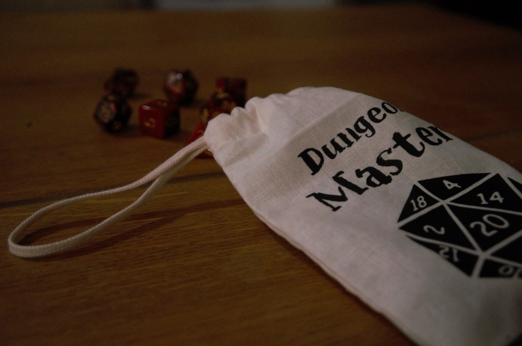
As an example for the vinylcutter I have made a small dice bag. I cut
the thermal transferfoil with the Silhouett Cameo using the provided sketch.
Then I removed all foil parts that I do not want to have on my bag.
Finally I put the foil on my material and pressed it with a mini press.
You can see it all in the video below
Design, lasercut, and document a parametric construction kit,
accounting for the lasercutter kerf,
which can be assembled in multiple ways,
and for extra credit include elements that aren't flat
We're supposed to build a construction kit.
So I asked myself what kind of construction kit I could build that would serve a purpose.
Me and some friends meet regularly to play Dungeon and Dragons and we have to visualize the landscape or dungeons.
We do this at the moment by drawing on paper.
So I thought that I would like to design a dungeon construction kit.
I ended up cutting with the settings:
Power: 50, speed: 100, frequency: 500
Dowlowd
dungen master stl
I deselected my construction kit in Fusion 360.
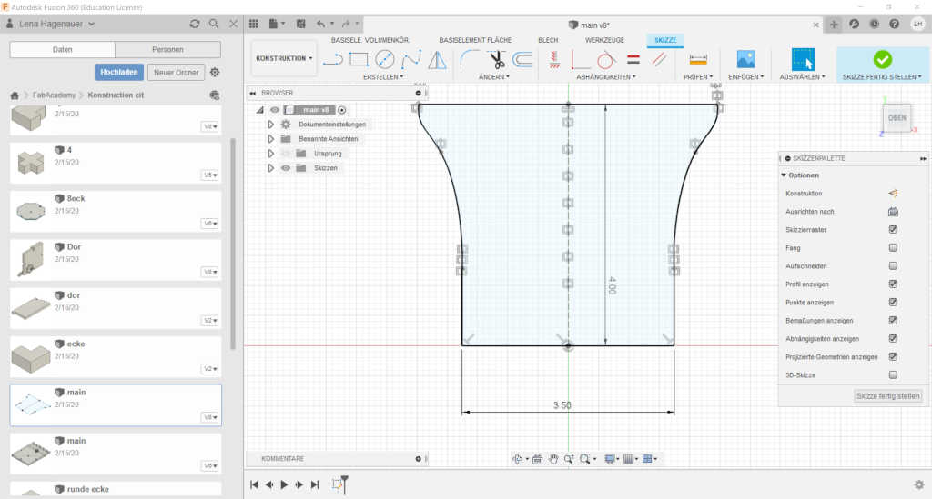
For my konstructio kit I first constructed my plug connection. So that I can change it later if I have thicker or thinner wood I created it as a skitz.
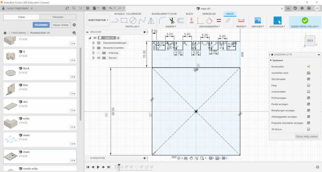
Then I designed a skitez for my main element.
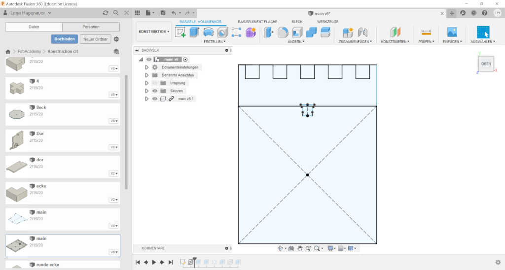
Then I pulled the skiteze from my conection into my aktulle scetch.
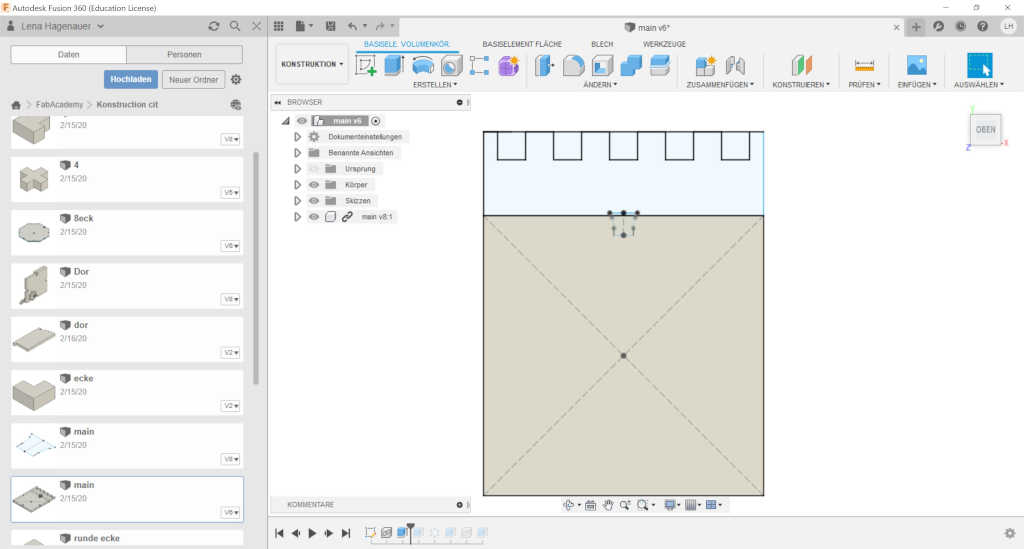
And I have extended my surface.
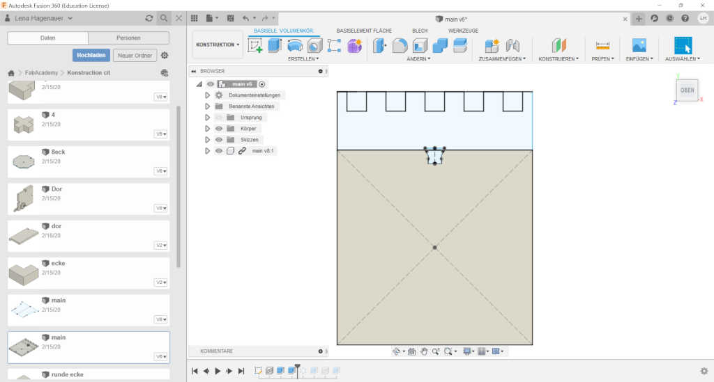
There I can now take my conectin away.
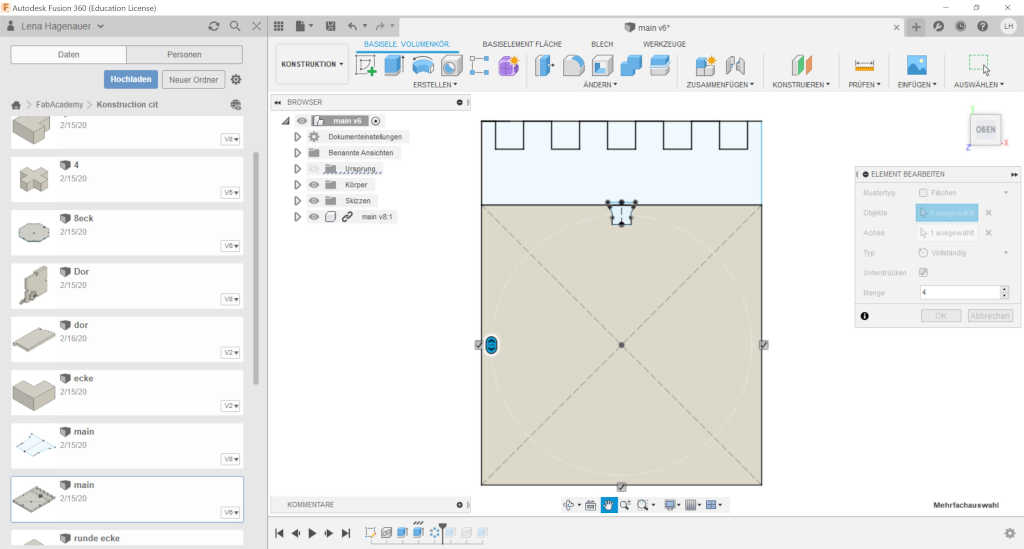
Since I need 4 of them I have put them in a round arrangement.
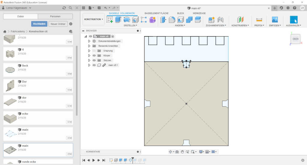
I cut these out again.
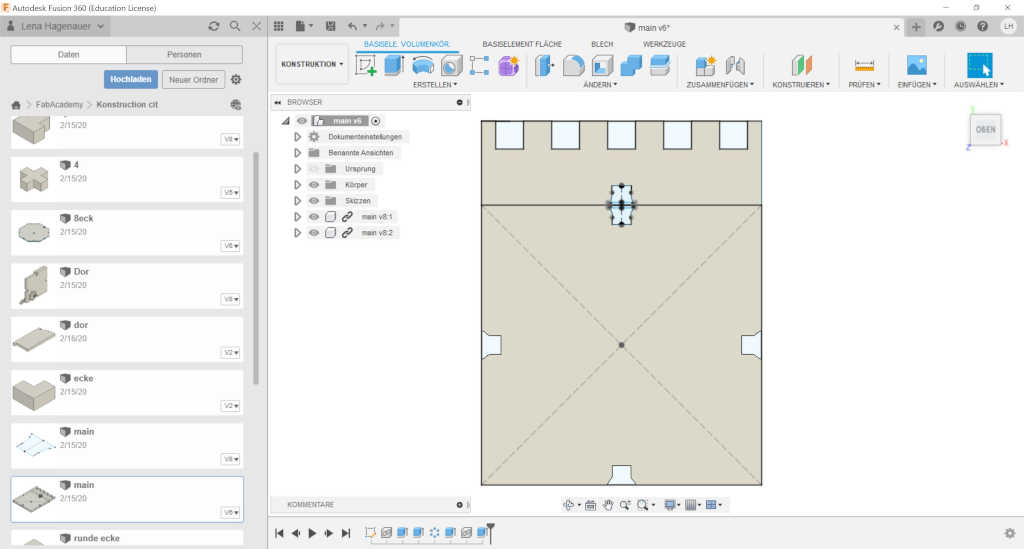
I can do the same thing with all my other sketches now. As soon as I change the distance in one of the main sketches I can do the same with 2 clicks in all the others.
As a last step I exported all files as svg files and merged them into one file to have them clearly arranged.
The red lines must be cut.
The blues should be marked.
The black surface should be engraved about 2 mm.
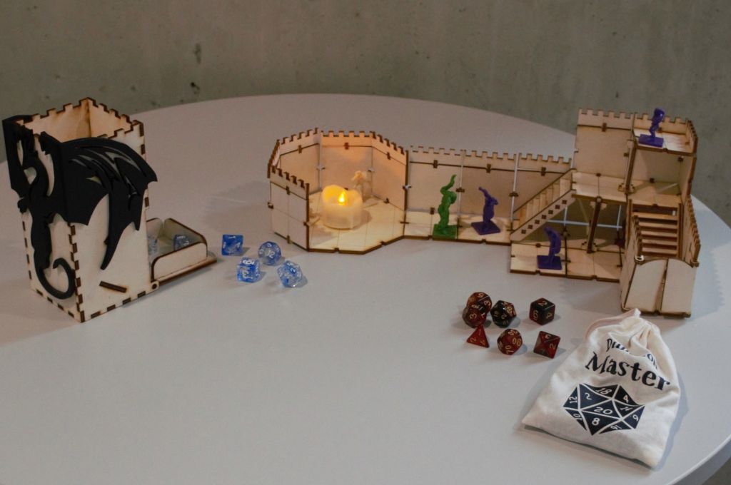
I sketched a kit with which you can build a dungeon. With floor plates, wall plates, doors, stairs and some decorations to complete the system.
Here you can see the notches which were designed with a bevel to make it easier to put together.
At other places I have used a system that locks into place.
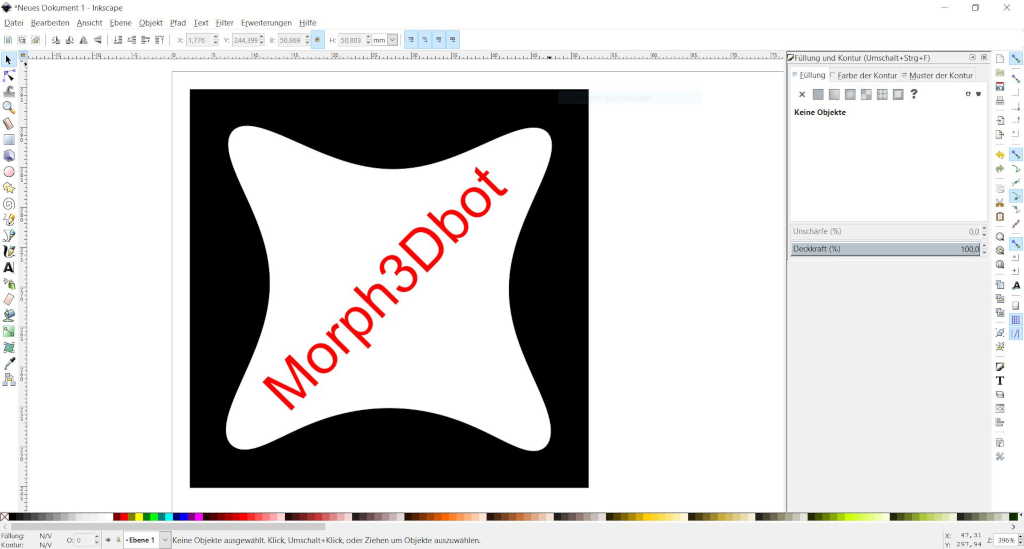
To send my drawing to the lasercutter, I use visicut.
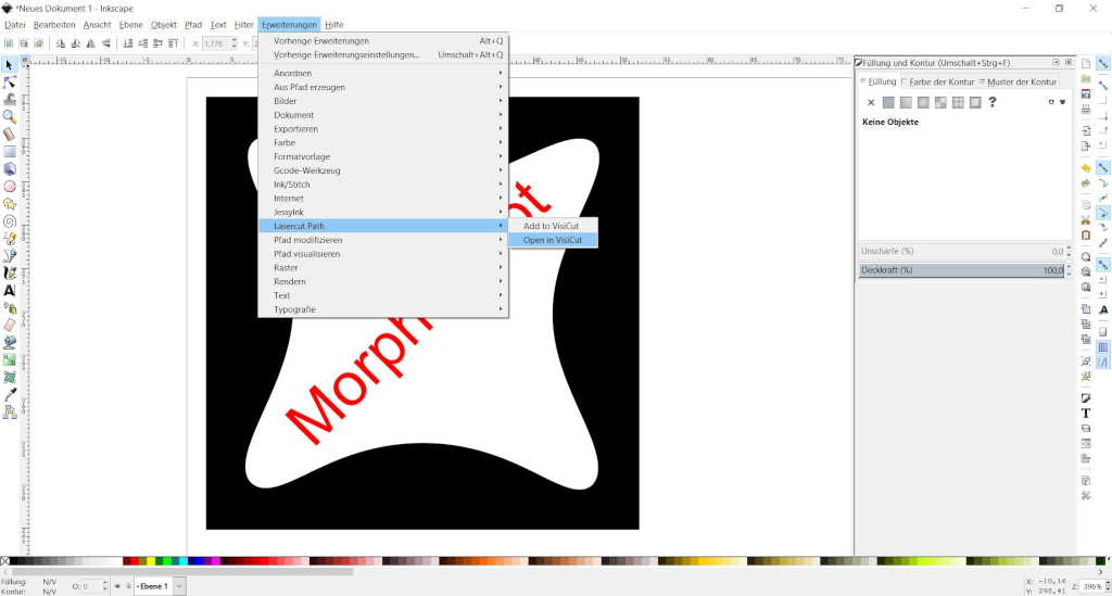
For this I go in the menu bar above on Extensions->LasercutPath->OpenInVisicut.
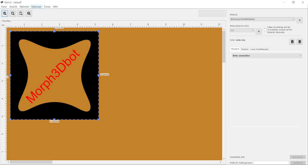
First of all I select my material from, in my case, the category wood. This gives me the right settings.
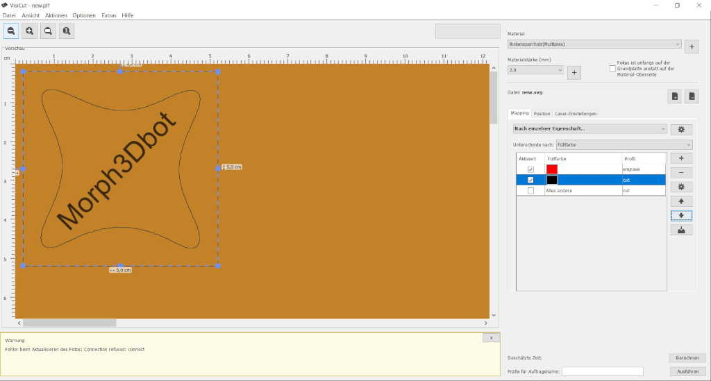
Then I have to choose what I want to do. Earlier, I have colored the single elements differently. Everything that is red will be engraved and everything that is black will be cut.
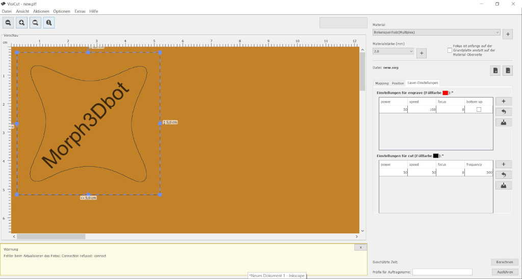
In the last screen you can see the settings and change them. To cut now I only have to press execute.
After I have sent my file to the laser cutter I have to make some last settings so I can't start cutting.
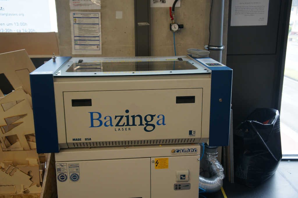
First, of course, I have to turn on the laser. In addition, also the compressed air which is switched on by the red lever above the cutter. And of course the filter which is located under the cutter and has a separate power button.
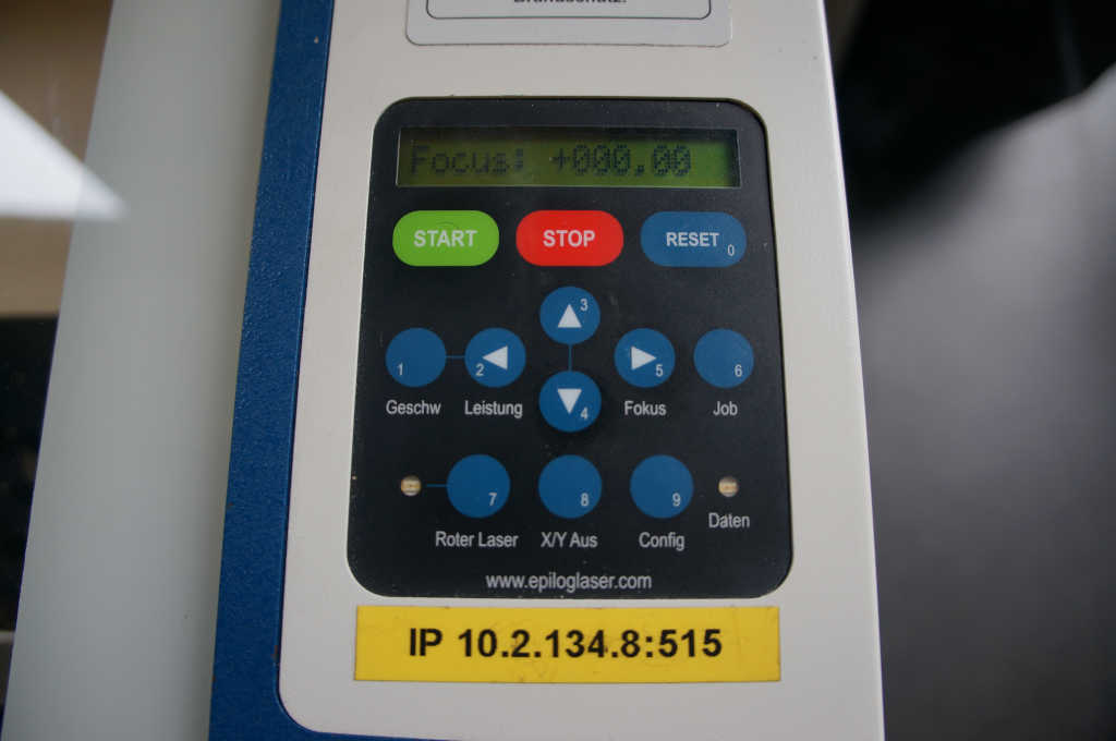
Now I have to adjust the height of the board caliberirn for this I press the focus button. After that I can adjust the height of the bed with the arrow keys up and down
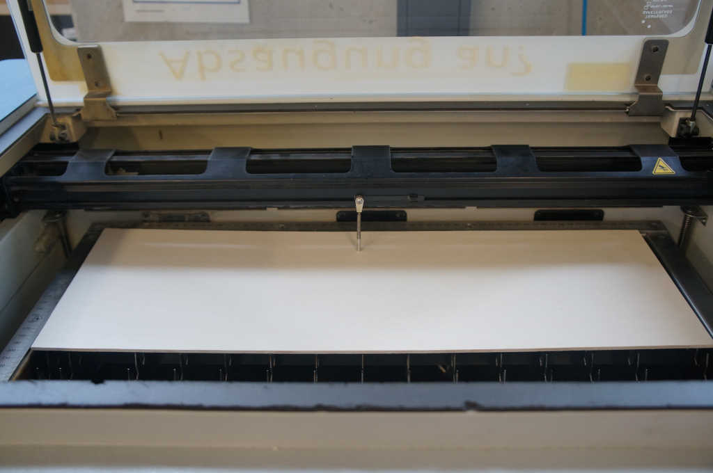
To see how far I have to adjust the cutting board I fold down the small leg. It must just scratch the surface of my material and I have the perfect height.
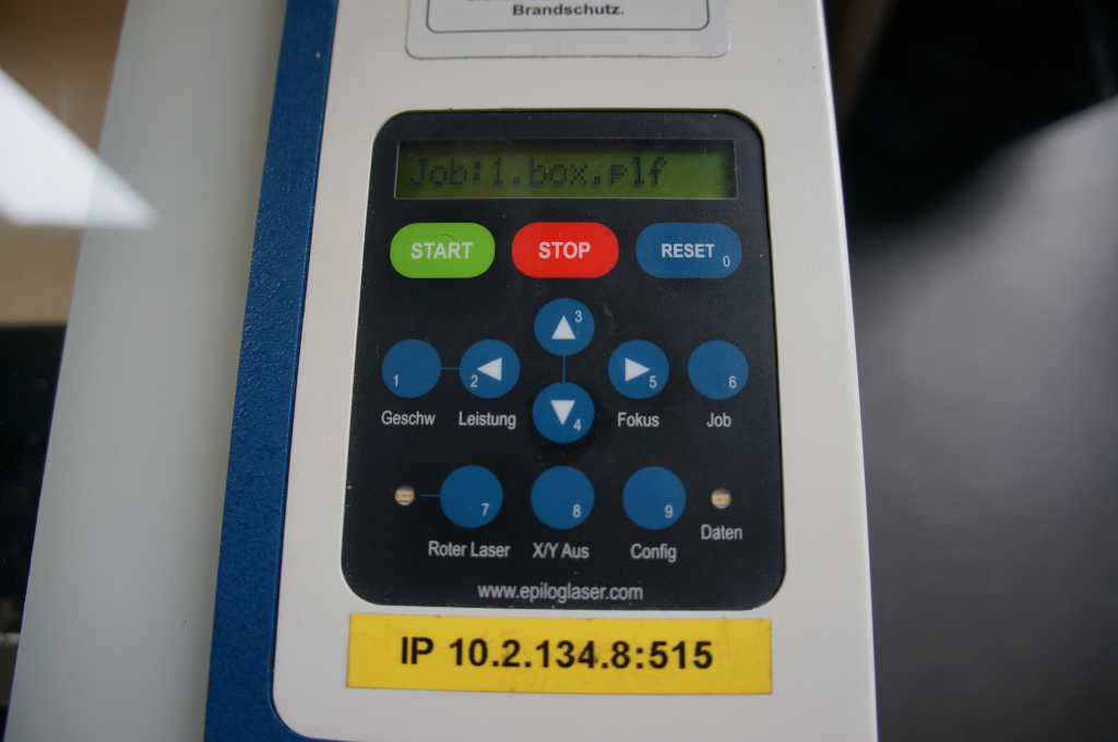
With stop I come back to the main menu and can select my job. Now it is important that you stay at the laiser cutter the whole time.
In the video below you can see the created and cut kit.
Here you can see some pictures.
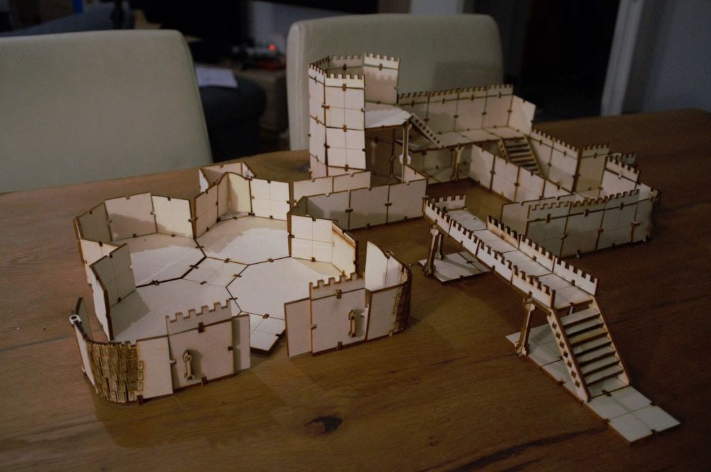
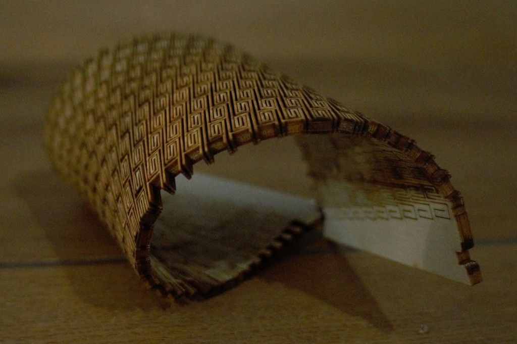
For the round corners I had to experiment a little bit. I wanted a pattern that looked a bit like stones. Unfortunately this didn't work out so I decided to use these designs. I searched a little bit which variants are already available and designed them like the already existing ones.
