use the test equipment in your lab to observe the operation of a microcontroller circuit board
What kind of test equipment do we have in the lab?
I found a multimeter, which is able to measure different electronic quantities.
It also has a voltage meter and a current meter. You can switch between AC
and DC measurement. Furthermore it has a resistance meter.
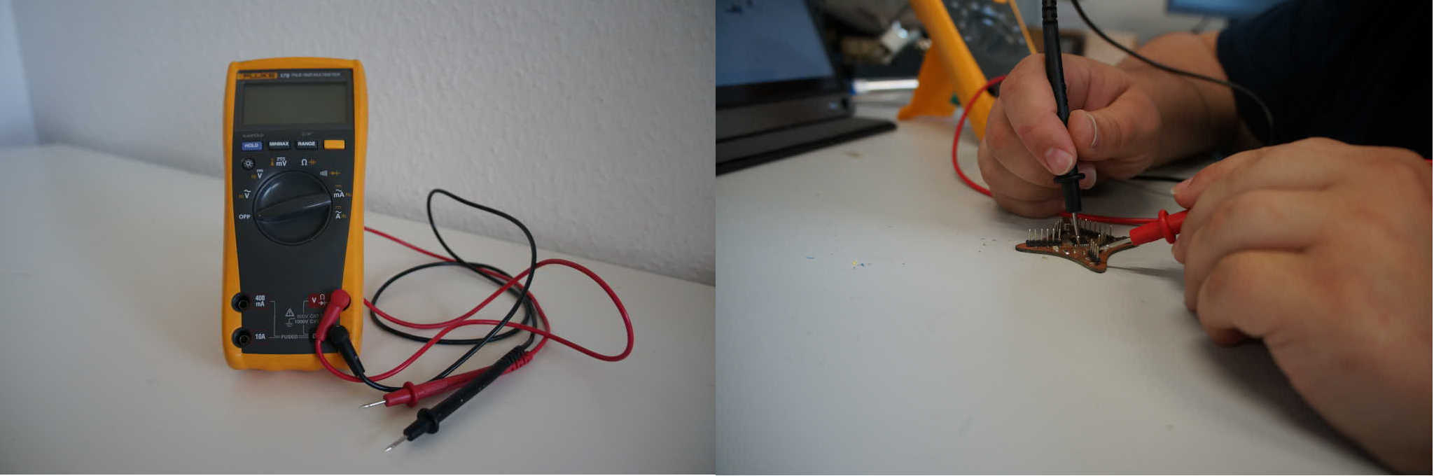
Mostly I used the 5 functions from the left. With them I can check if the targets are connected to each other and conducting electricity. To do this I hold the two tips to one of the two lines and if there is a auditory signal when they are connected. With this I always check my boards for short circuits before I connect them to the power for the first time.
The second test equipment we have with us in the labor is an oscilloscope. This is also an electronic measuring device but in contrast to the multimeter it is able to show us only the voltage as a time course. For this purpose it has a screen on which a 2 dimensional coordinate system is displayed in which the e-curve or the curves (if the device has several inputs) can be displayed. Unfortunately I can't do any tests with it at the moment because one of our employees took it with him into his home office due to Corona.
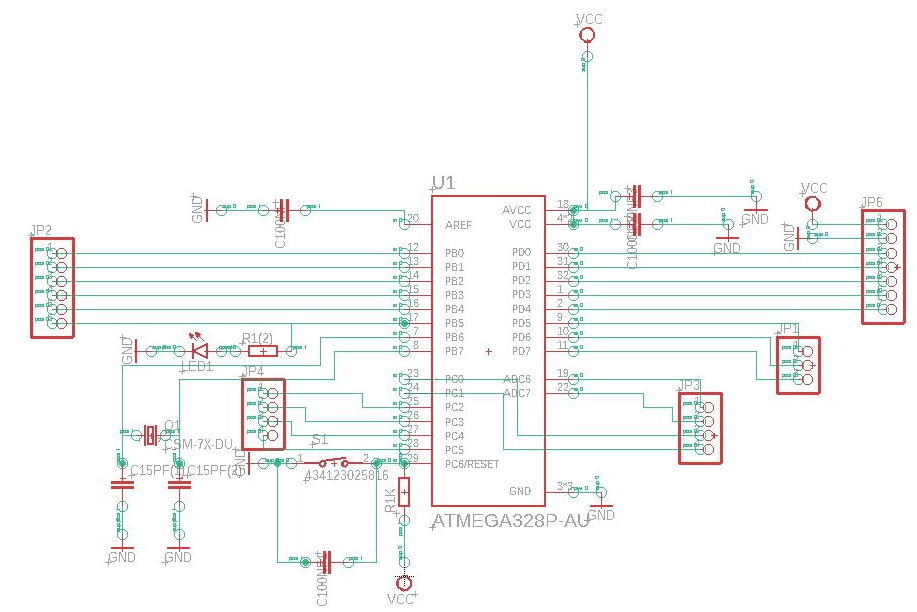
redraw an echo hello-world board,
add (at least) a button and LED (with current-limiting resistor)
check the design rules, make it, and test it
extra credit: simulate its operation
| Parts | Type | Value | In Eagle |
|---|---|---|---|
| ATmega328P | TQFP | - | ATmega328P-AU |
| Resistor | 1206 | 1KΩ | R1K, R1k(2) |
| LED rad | 1206 | - | LEDRAD |
| Capacitor | C | 100nF | C100NF, C100nf1 |
| Capacitor | C | 15pF | C15pF(1), C15pF(2) |
| Quarrz | 16MHZ | Q1 | |
| Button | - | 434123025816 |
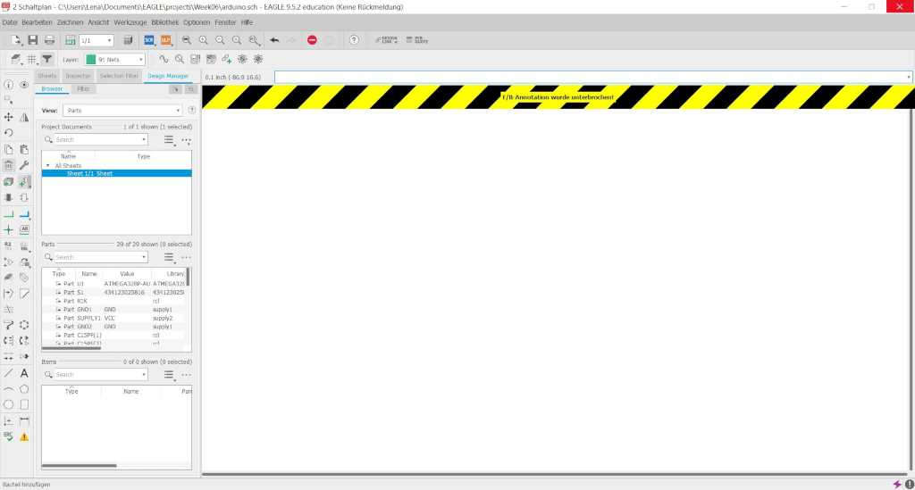
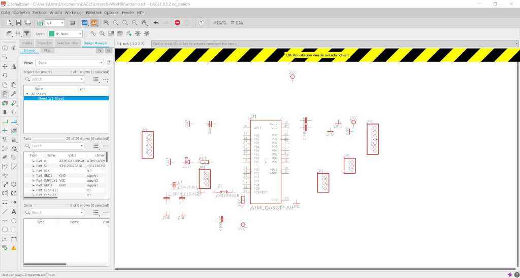
First I create a new circuit.
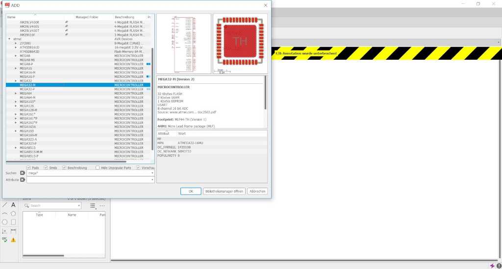
Same as two weeks ago. I can add my components by clicking on the marked symbol in the left menu bar. To do this I have to look up which component I have and add it. Not all of my parts were in the library. I searched them on the internet and added them.
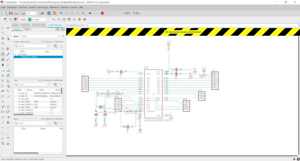
Now I have to connect all my components, according to the schematic I have drawn with my instructor. Therefore I select the green line on the left menu and connect everything.
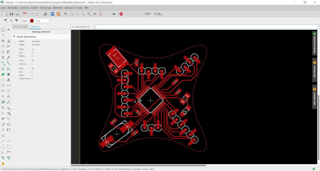
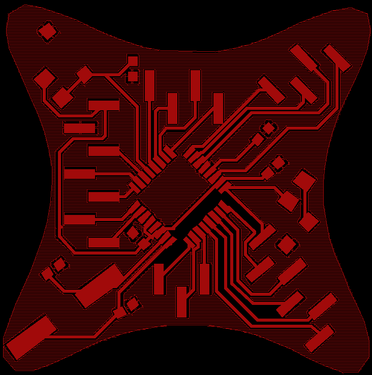
After that I have to draw the board myself. For this I zoom in.
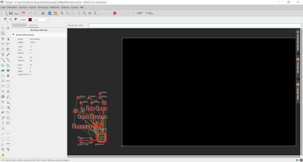
Now I need to sort my parts.

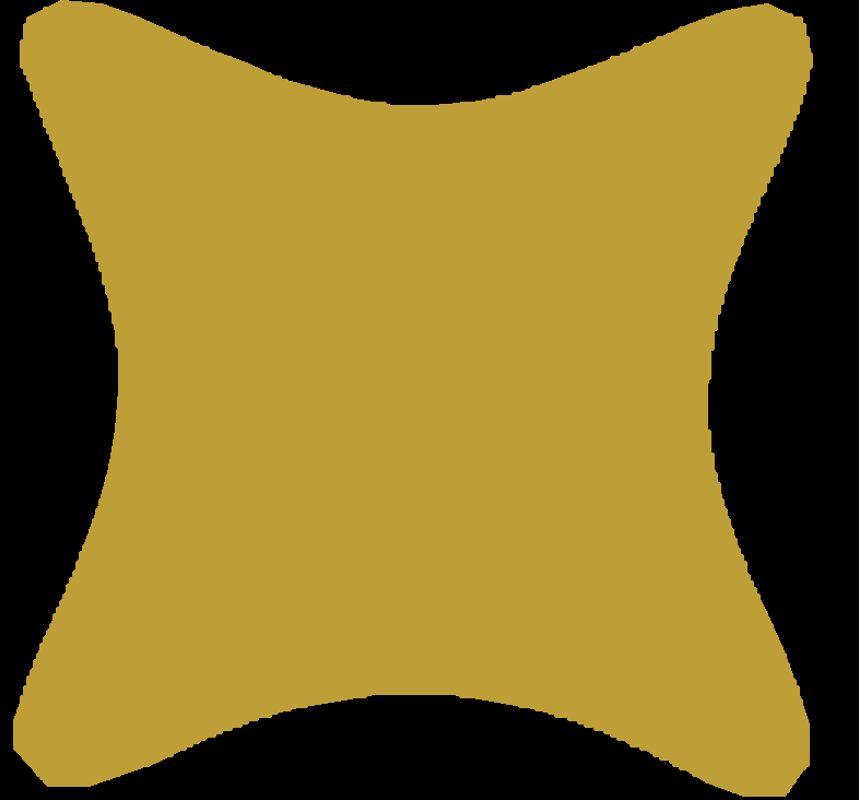
To get the special shape I exported my SVG file from Fusion to a polygon for eagle. I used the following: SVG to Eagle.
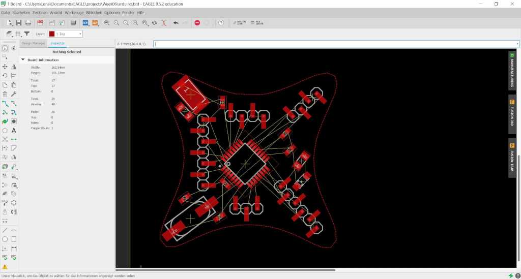
I have to puzzle a little and also remove some pin strips to make everything fit on the mold. In the next step I will try to draw a two sided board.
I connect the components.
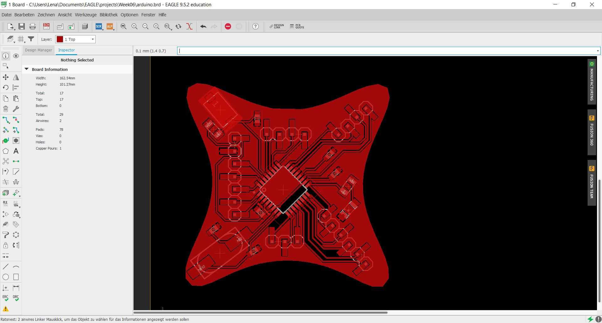
Because of the above mentioned space problems I left out all GND connections when drawing the tracks and now connect them by setting the remaining free space as GND. To do this you have to declare the polygon as GND and then click on the corresponding symbol in the left menu bar.
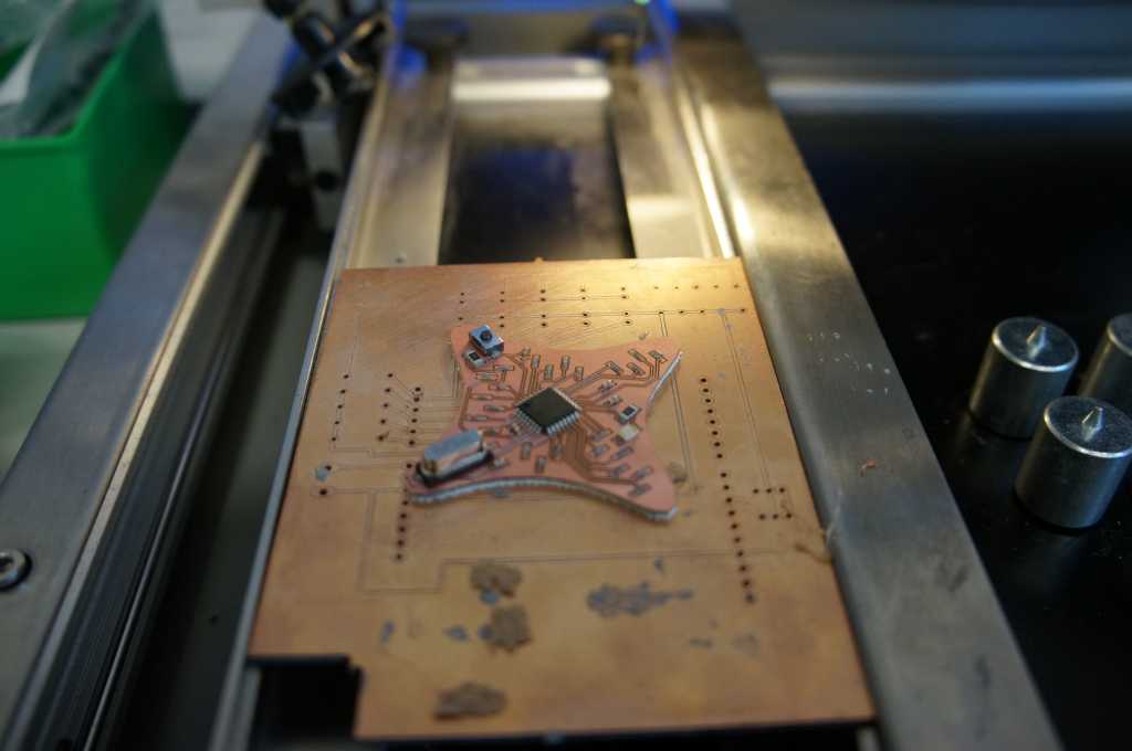
Now I still have to mill and assemble the circuit board.
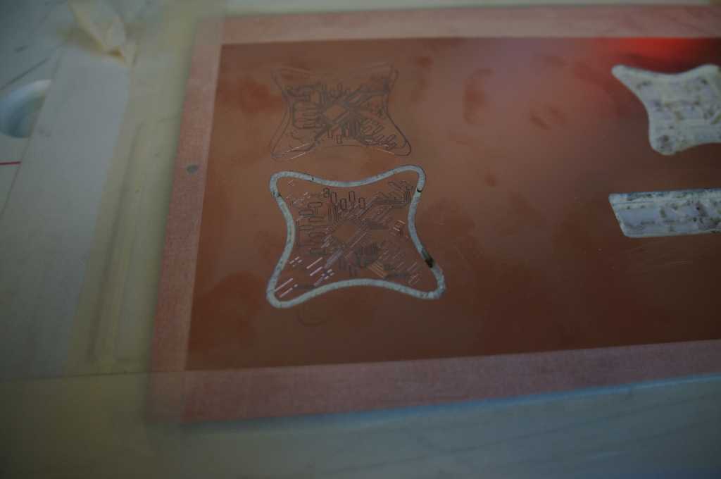
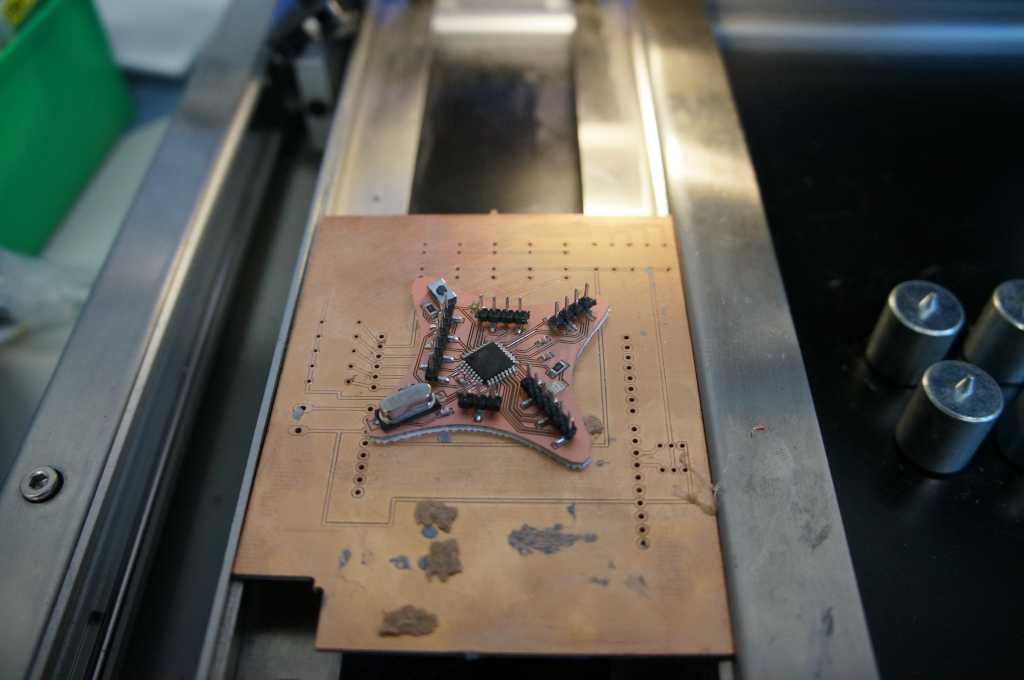
In the picture you can see the final cut of the circuit board. In the background you can see my first try. I took the wrong settings for the outline and he just engraved it and did not mill it.
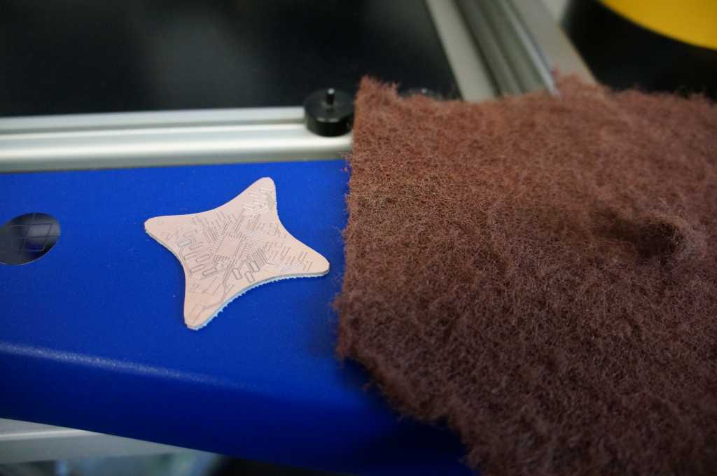
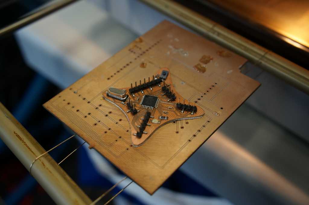
Now I remove dirt and fingerprints so that the board conducts everywhere.
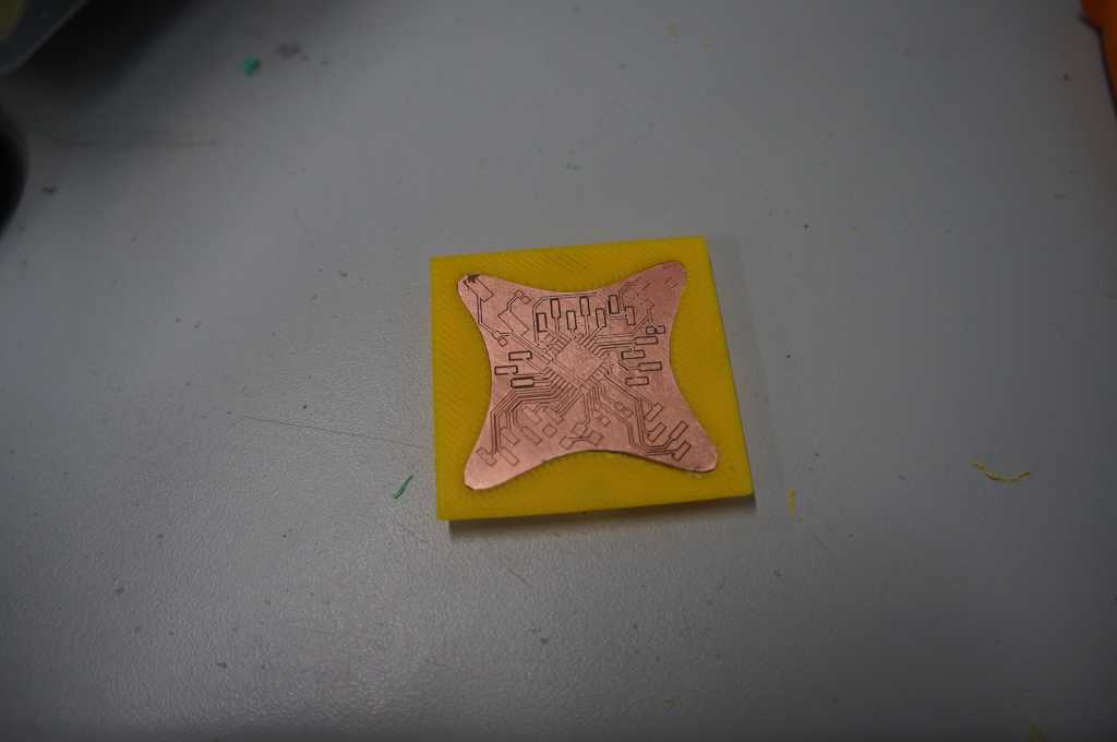
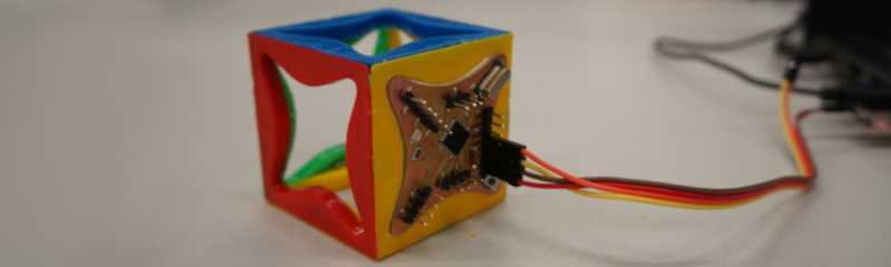
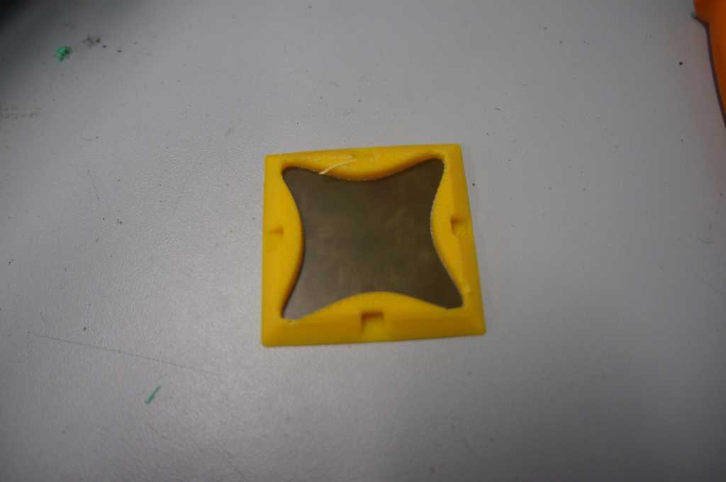
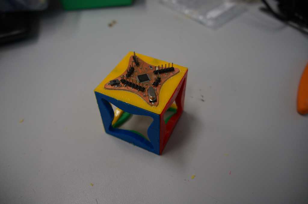
With a little effort the board fits into the 3D printed parts.
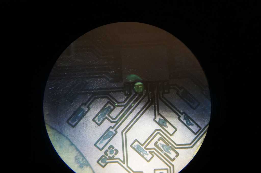
This time the parts have become very small so I applied the solder paste under our 3D microscope.
Now I can start to program my board. But before I can start programming the microcontroller I have to burn the
bootloader to the board.
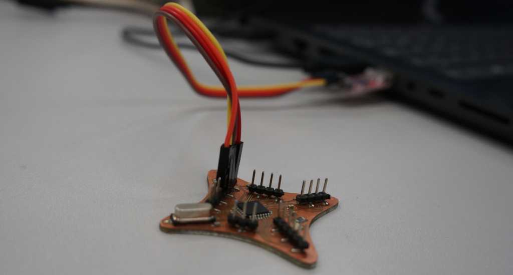
Since I haven't found the time to fix my programmer problems with my ISP my Instractr Tobi has given me another programmer so I can continue.
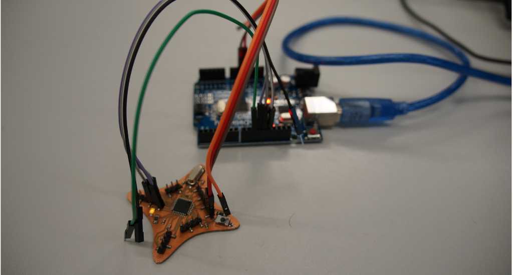
To burn the bootloader I connect the pins like in the table below with an Arduino. And download the sketch under examples -> Arduino ISP -> Arduino ISP to the Arduino.
| Arduino as ISP | ATMega328P |
|---|---|
| MOSI/D11 | MOSI/D11 |
| MISO/D12 | MISO/D12 | SCK/D13 | SCK/D13 |
| D10 | Reset |
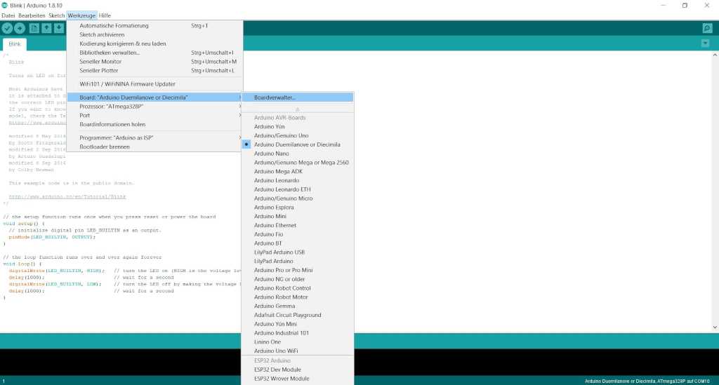
The next step is to open the Arduino IDE. There I select Tools > Boards and then Arduino Duemilanove or Diecimila.
Then I select which processor I'm using: Tools > Processor > ATMEga328P.
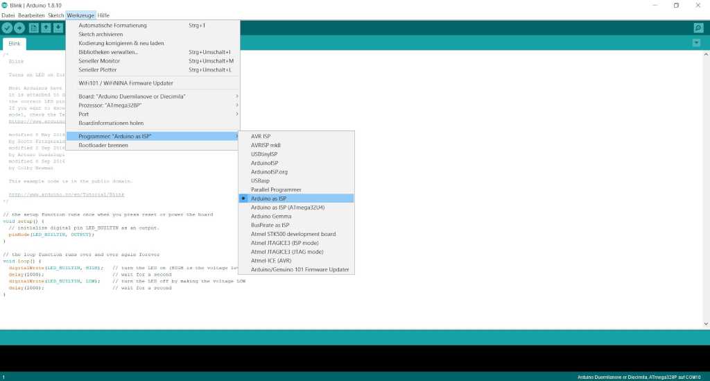
And for the programmer Tools > Programmer > Arduino as ISP.
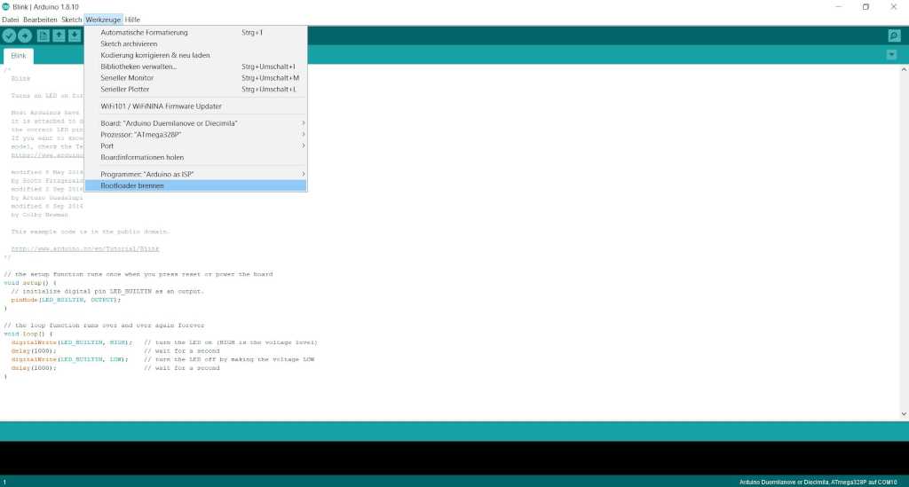
The last step is to select Tools > Burn Bootloader. This may take a few minutes but then the microcontroller can be programmed.
Now I connect the USB to TTL with my circuit and can download a first sketch. If the USB to TTL doesn't have a reset pin you need to press the reset button until it starts to download, and then release it. If you do not do this it won't work.
| Programmer | ATMega328P |
|---|---|
| 5V | 5V |
| GND | GND | RX | TX |
| TX | RX |
I used the Blink test program from the Arduino IDE. This can be found under Examples->Basic->Blink.