measure something: add a sensor to a microcontroller board
that you have designed and read it
Which sensor should I try?
There are a lot of possibilities: ultrasonic, temperature, touch, IR and many, many more.
Since my final project is to be a modular robot system, there are many options that would be useful.
But of course I can't test everything sensor I know.
Therefore I have thought about which sensors would be especially useful. First I will test an IR sensor.
I have chosen this one because of its versatility - it can determine distance,
detect an object, or even recognize a line.
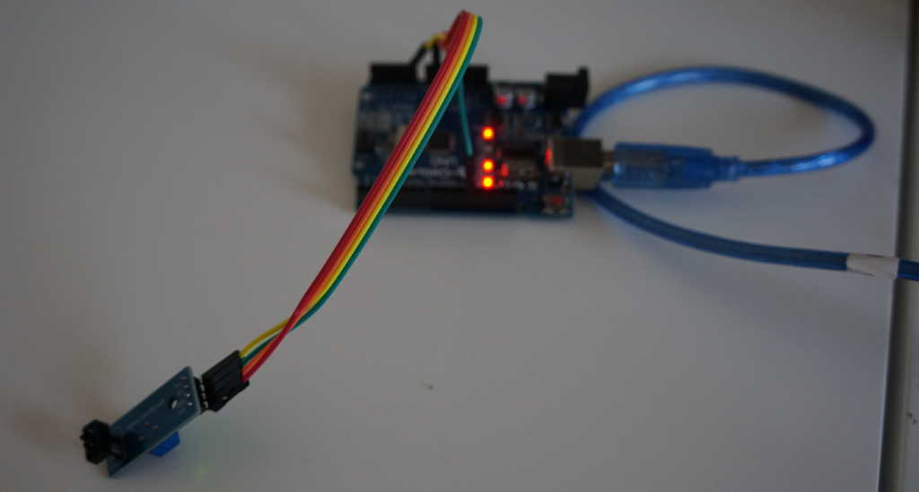
How does the sensor work?
On the sensor there is an Infrorot LED which is continuously turned on.
(This infrared light is not visible to the human eye, but if you still
want to see if the LED is working you can look at the sensor with a
mobile phone camera and if it is working you will see a purple shimmer.)
In the same line of sight, but separated by a piece of plastic,
a photo resistor is mounted (see picture).
This measures the brightness of the reflected light.
Which is reflected differently from different surfaces, the measured
value also depends on the distance to the object.
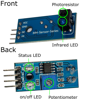
The sensor has four pins VCC, GND, D0 and A0. This enables the sensor to return the signal in both digital and analog form. With the digital signal, the threshold at which the light intensity of pin D0 switches from 0 to 1 can be set on the rotary potentiometer. The analogue pin directly returns the value of the sensor. The VCC pin has to be connected to the 5V pin of the microcontroller and the GND pin to GND (see diagram).
In this video you can see how this sensor works on the line detection and also distance.
The program reads the serial and digital pin of the sensor and displays them on the serial monitor. For the analog input the method analogRead(pin) is used which reads the current between 0 and 5 volts and outputs values between 0 and 1023. For the digital input I use digitalRead(pin) which outputs 0 when no current is present and 1 when current is present. The two values are then displayed on the serial monitor.
              //set variables
              int SensorAnalog = A0;
              int SensorDigital = 8;
              int analog;
              int digital;

              void setup()
              {
                Serial.begin(9600);
                pinMode(SensorDigital,INPUT);
              }

              void loop()
              {
                //read Analog pin A0
                analog = analogRead(SensorAnalog);

                //read digital Pin 8
                digital = digitalRead(SensorDigital);


                //print values on monitor
                Serial.print("Digital: ");
                Serial.print(digital);
                Serial.print(" Analog: ");
                Serial.println(analog);
                delay(500);
              }
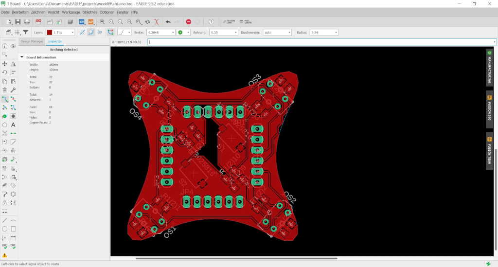
Since I don't have access to the lab at the moment, I could only draw the board in Eagle.
It's a board with four distance sensors with which a robot can take care that it
doesn't hit a wall. The board can be put on the new designed board (see final).
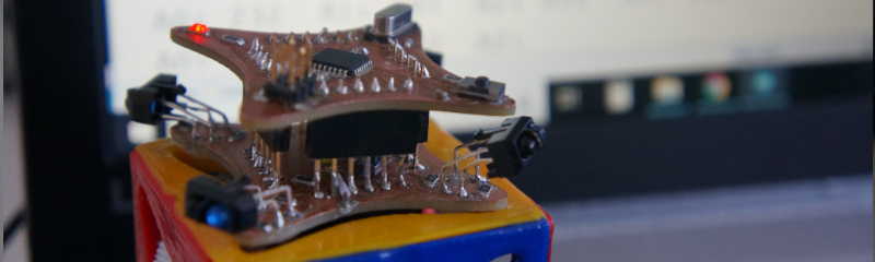
Addendum from 18.04.2020 I am finally allowed to go back to the lab, but only under special precautions.
After we made a lot of faceshields and other protection against corona, I found the time to mill and assemble the
board.
| Parts | Type | Value | In Eagle |
|---|---|---|---|
| Resistor | 1206 | 10KΩ | R10(1-4) |
| Resistor | 1206 | 1KΩ | R1 |
| Resistor | 1206 | 200Ω | R200(1-4) |
| Resistor | 1206 | 1KΩ | R1(1) |
| LED yellow | 1206 | - | LEDYELLOW |
| Pin Header 1x6 | PINHD6 | - | JP1-4 |
| Taster | - | - | 434123025816 |
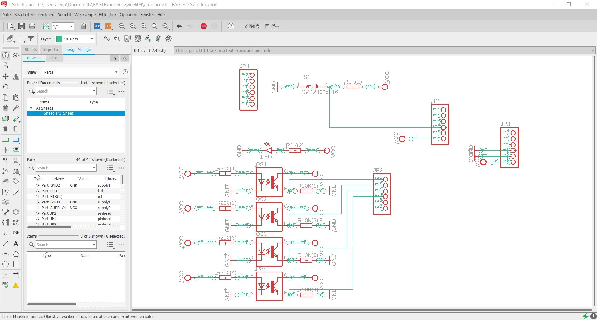
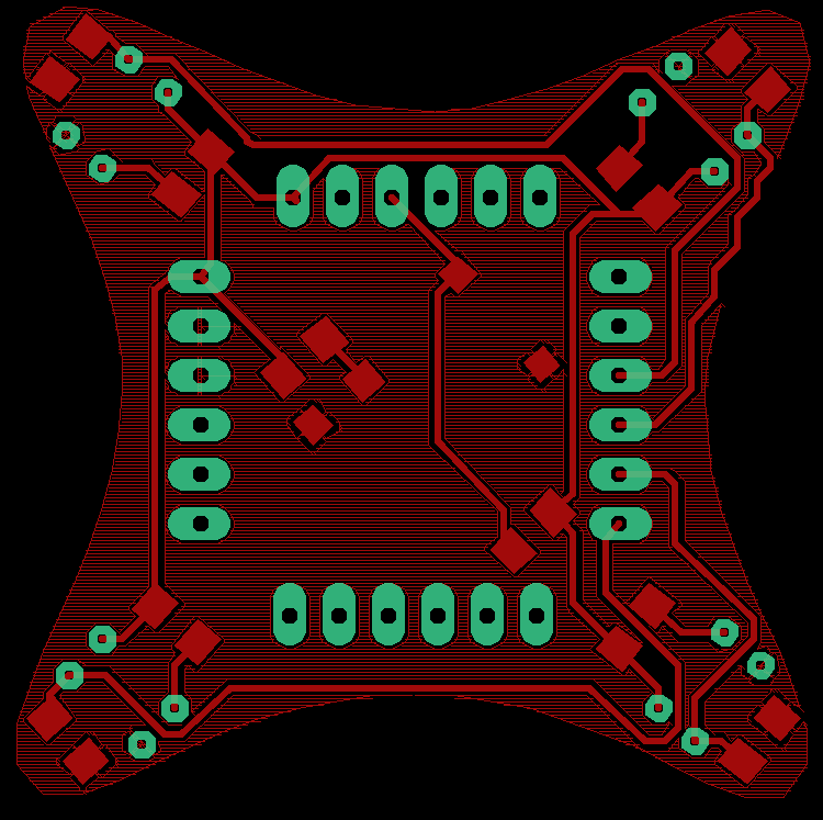
I designed a distance board.
In each "corner" there is an IR sensor which I
used as a voltage divider with a resistor and
connected it to one of the analog pins.
Same direction of view but with plastic in
between there is one IR-LED in each corner.
Furthermore the board has a status LED which
shows if the board has power and a button which is connected to a digital pin.
Because there are not many parts it was not so difficult to place them all on the board. I just had to make sure that the pin headers are in the same position as on the final board so I can put them together.
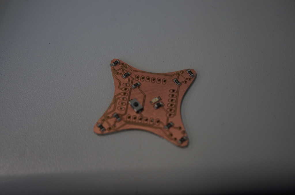
This time I had some problems with the milling of the circuit board. At the first try I forgot to add the file with the holes because my last boards didn't have them. Then, during my second try, the software had problems with the settings in my file. As a solution, I increased the distance between two tracks so that the thin cutter has to be used less. Then I placed the board at the same position as before a second time and only milled the tracks again.
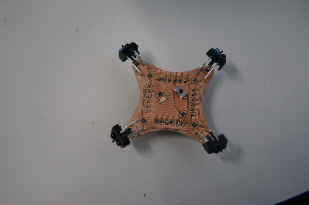
When I assembled the board everything worked fine, so I can program it now.
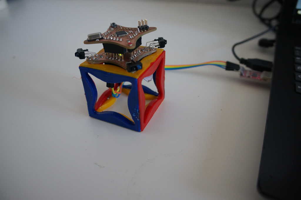
And it fits on the motherboard.
I have written a small program which displays the sensor values on the screen. Furthermore a LED lights up as soon as something approaches one of the sensors.
        int ai0;
        int ai1;
        int ai2;
        int ai3;

        void setup()
        {
        Serial.begin(9600);
          pinMode(13, OUTPUT);
        }

        void loop()
        {

        ai0 = analogRead(A0);
        ai1 = analogRead(A1);
        ai2 = analogRead(A2);
        ai3 = analogRead(A3);

        //print values on monitor
        Serial.print("  A0: ");
        Serial.print(ai0);
        Serial.print("  A1: ");
        Serial.print(ai1);
        Serial.print("  A2: ");
        Serial.print(ai2);
        Serial.print("  A3: ");
        Serial.print(ai3);
        Serial.println(" ");

        //turn LED on when any sensor has a bigger value than 700
        if(ai0 > 700 || ai1 > 700 || ai2 > 700 || ai3 > 700){
          digitalWrite(13,HIGH);
        }else{
          digitalWrite(13,LOW);
        }


        delay(20);
        }
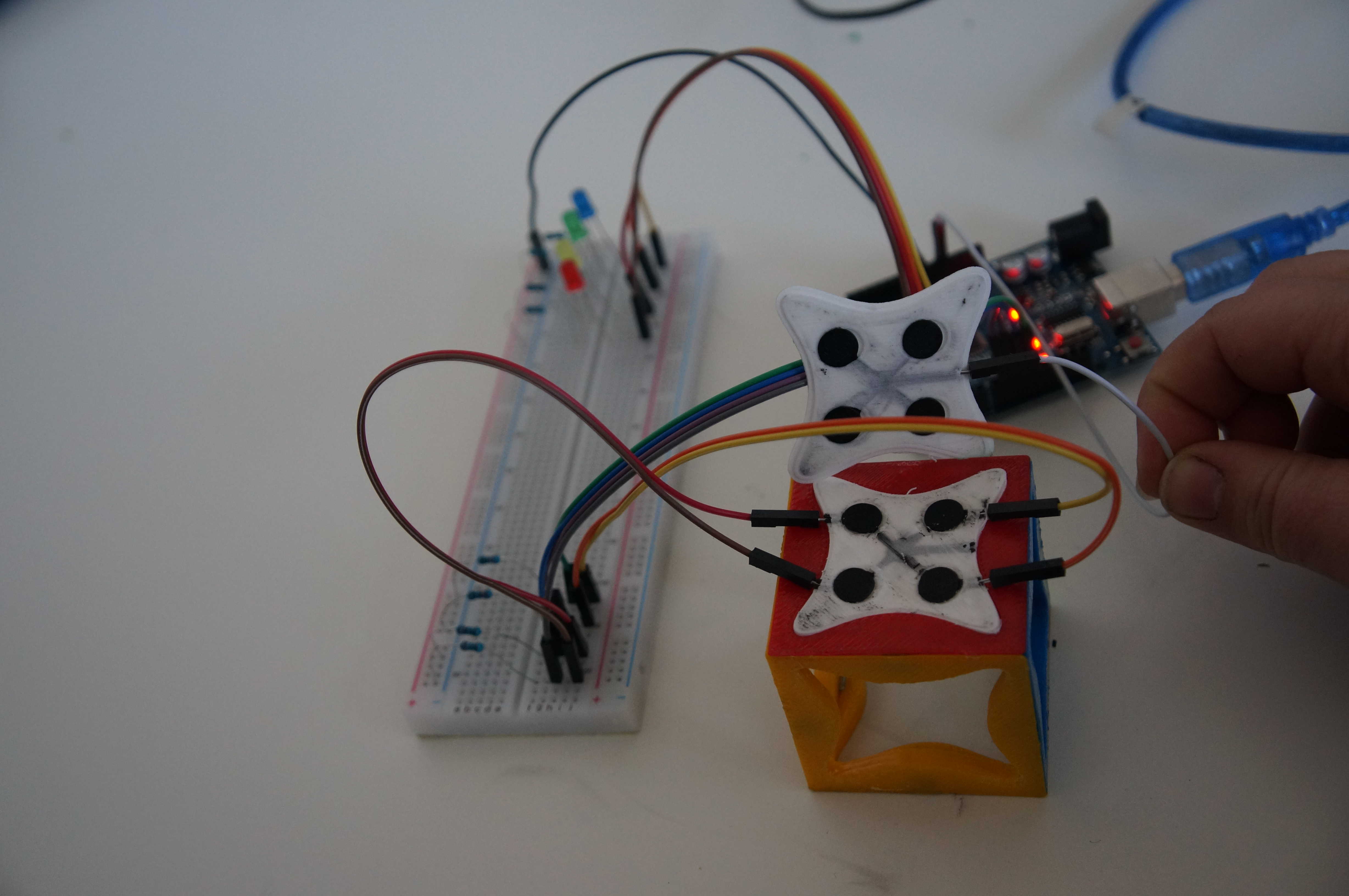
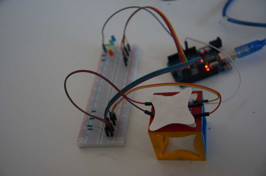
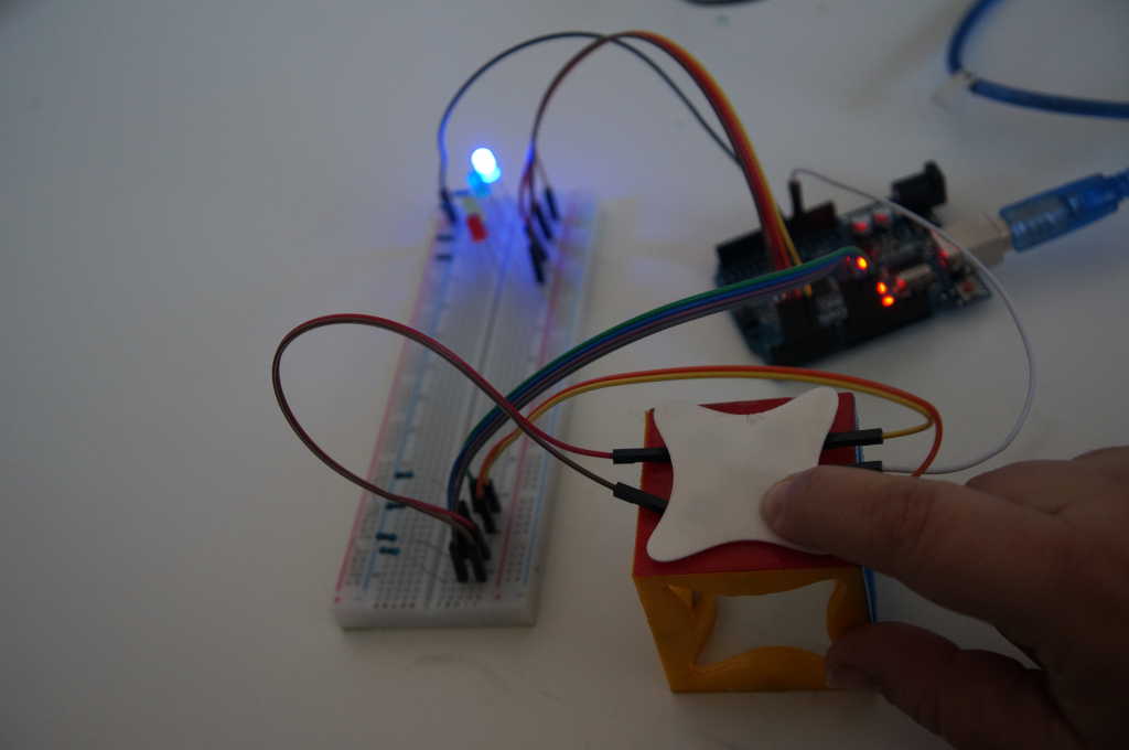
I was a little frustrated this week because I can't try out my newly designed boards and thought about what else I could do. It occurred to me that I still have some conductive film, so maybe I can make something cool with it. So I tried to print a button.
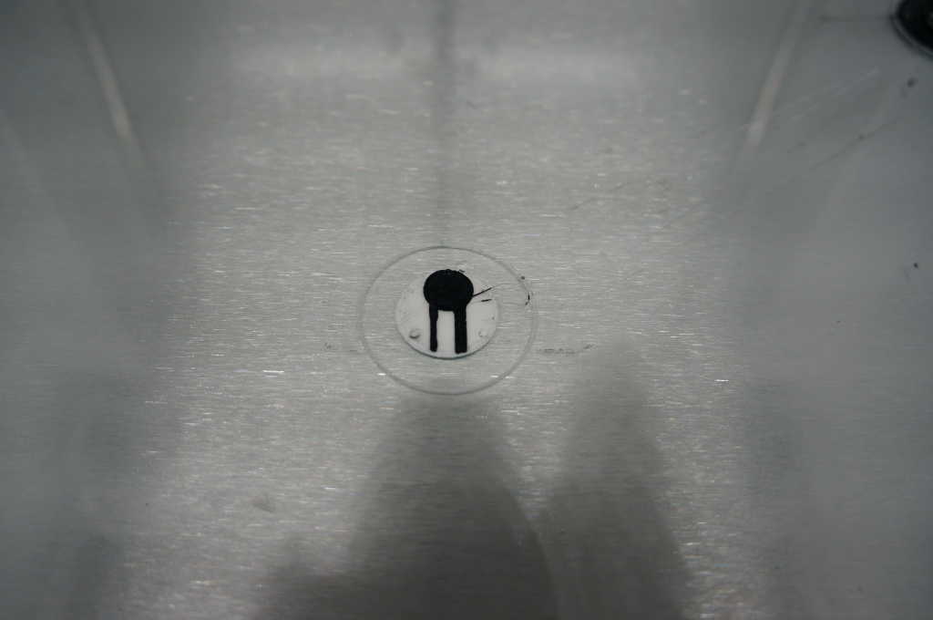
So I designed a print from 2 materials. The white is TPU and the black is the conductive material. In the picture you can see my first test which worked. I could measure a voltage difference with the Arduino as soon as I touched the conductive surface.
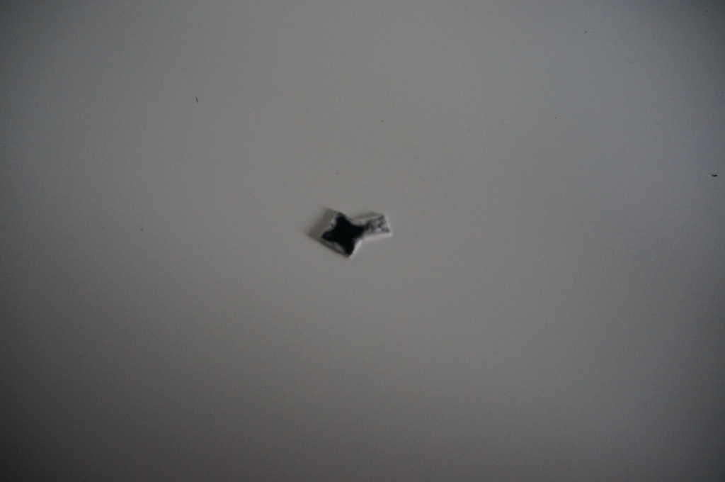
Now I can create a button of any shape.
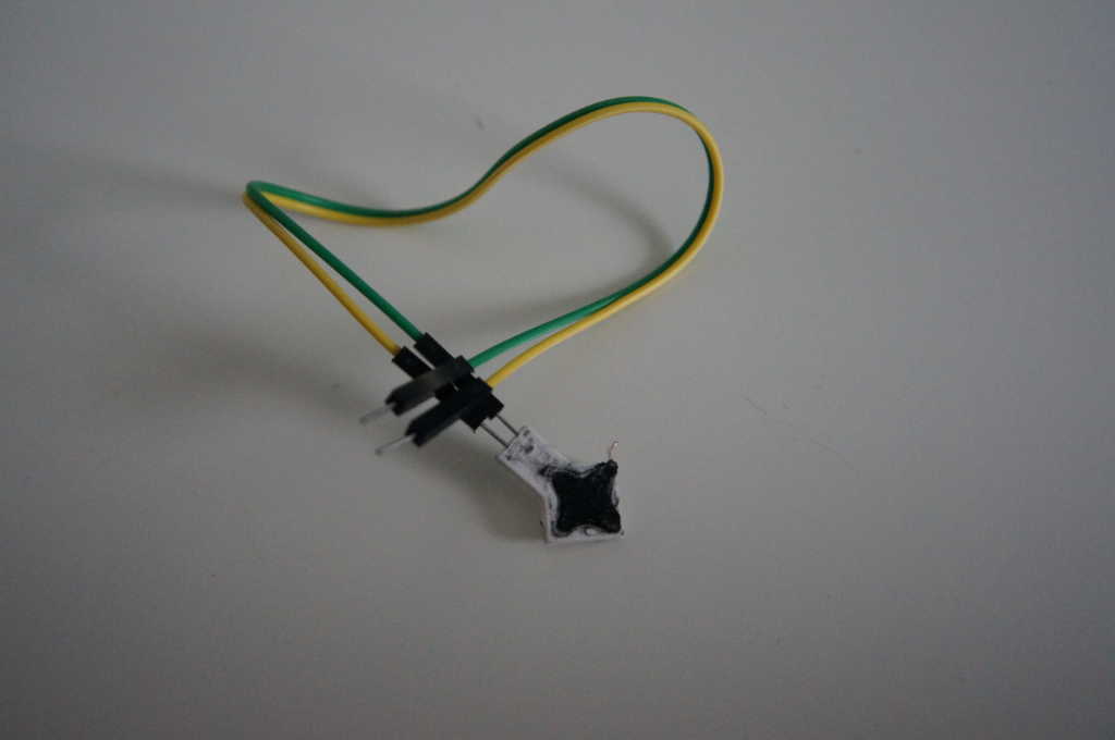
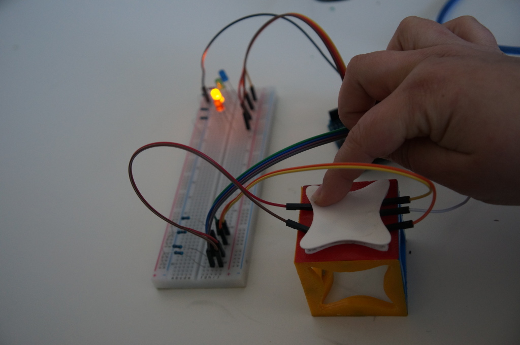
Since it was difficult to connect the wires from the Arduino to the sensor, I made sure that I put holes for the cables in the second print.
It works very well at first, but I will work on it a little bit more, since there are now completely new possibilities ;)
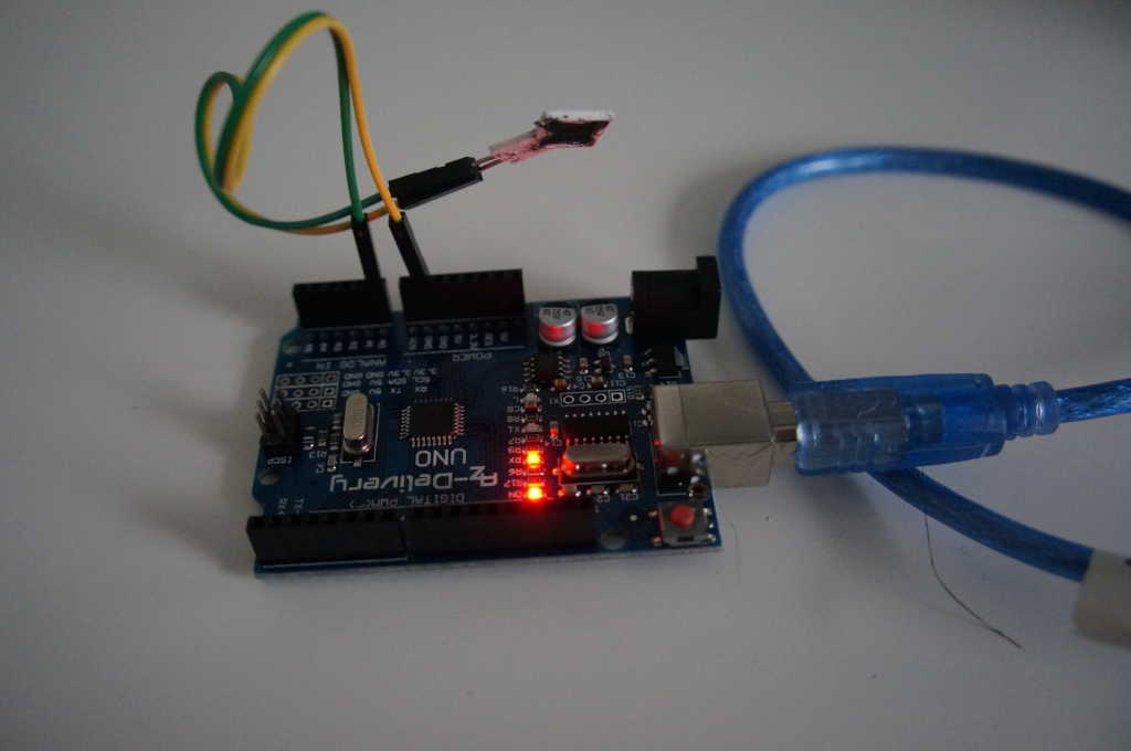
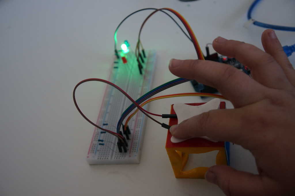
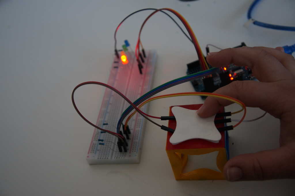
In this Video you can see when I touch the sensor the LED 13 from the Arduino turn on.
In this video you can see how the printed sensor works.
probe an input device's analog levels and digital signals
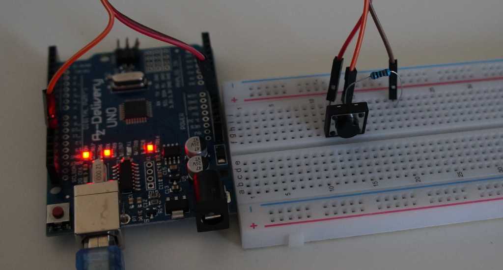
For my first test I took a probe and measured a digital signal.
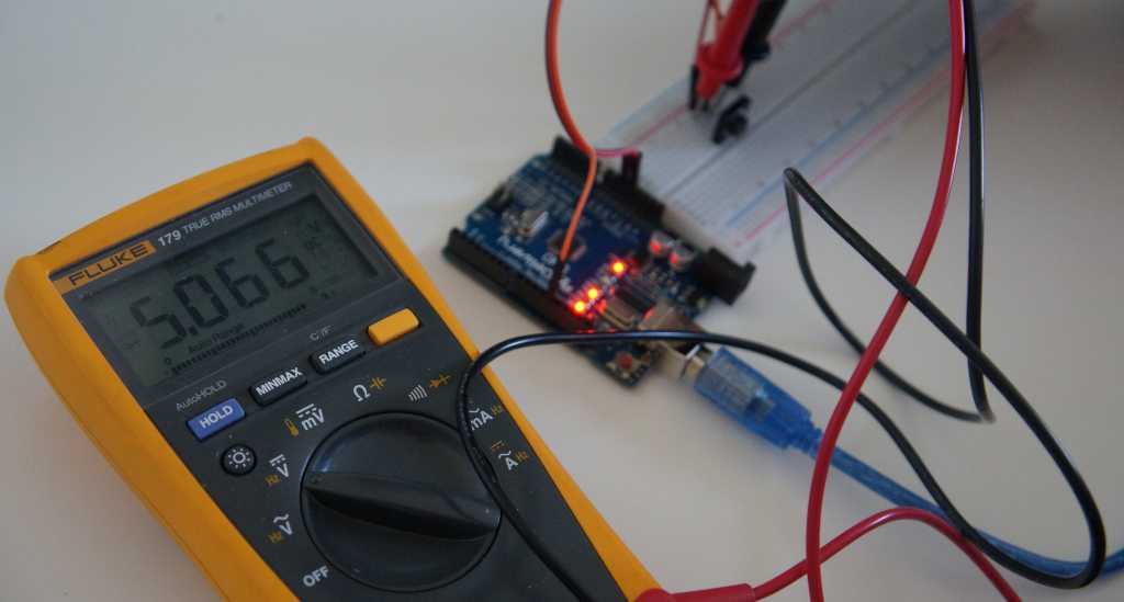
Then I used a multimeter, which I have at home, to measure the voltage at the button. As we can see here the resistor is built in so that we have a pull down resistor. We have 5V when the button is not pressed.
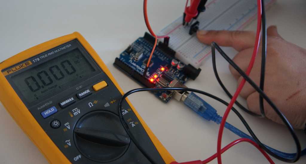
As soon as we press the button we have 0 volts.
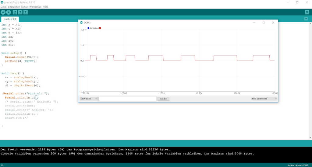
Here we can see the pressing of the digital input in the serial plotter of the Arduino IDE.
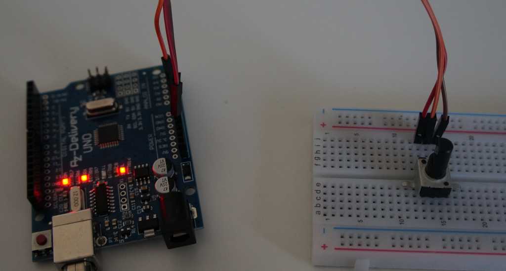
Next I connected a potentiometer to measure a system signal.
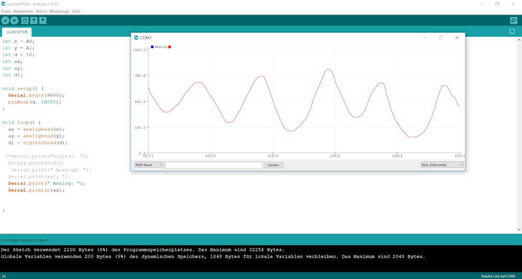
Again you can see very well in the serial plotter how it changes the voltage when I turn the potentiometer.
At last I used the measurement again with the IR sensor which gives me a digital and a serial signal at the same time.
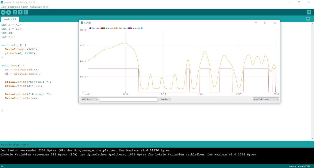
The digital signal has a value of 1 or 0 whereas the analog signal has a value between 0 and 1024 so we can see both at the same time. Here you can see both signals from the same sensor and you can see where the threshold of the digital signal is.
Ir sensor:
small printed touch sensor:
getBoundingClientRect printed touch sensor: