
test the design rules for your 3D printer(s)
In our Fablab, we have various Ultimaker printers. I ran the design rules for the Ultimaker 2+ and the Up Mini 2
from Tiertime.
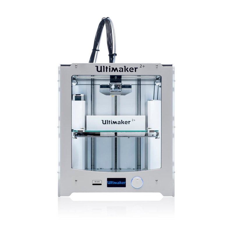
| Workspace | 223 mm x 223 mm x 205 mm |
|---|---|
| Filament | 2,85 PLA |
| Technology | FDM |
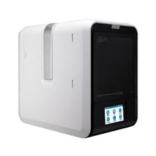
| Workspace | 120 × 120 × 120 mm |
|---|---|
| Filament | 1,75 ABS |
| Technology | FDM |
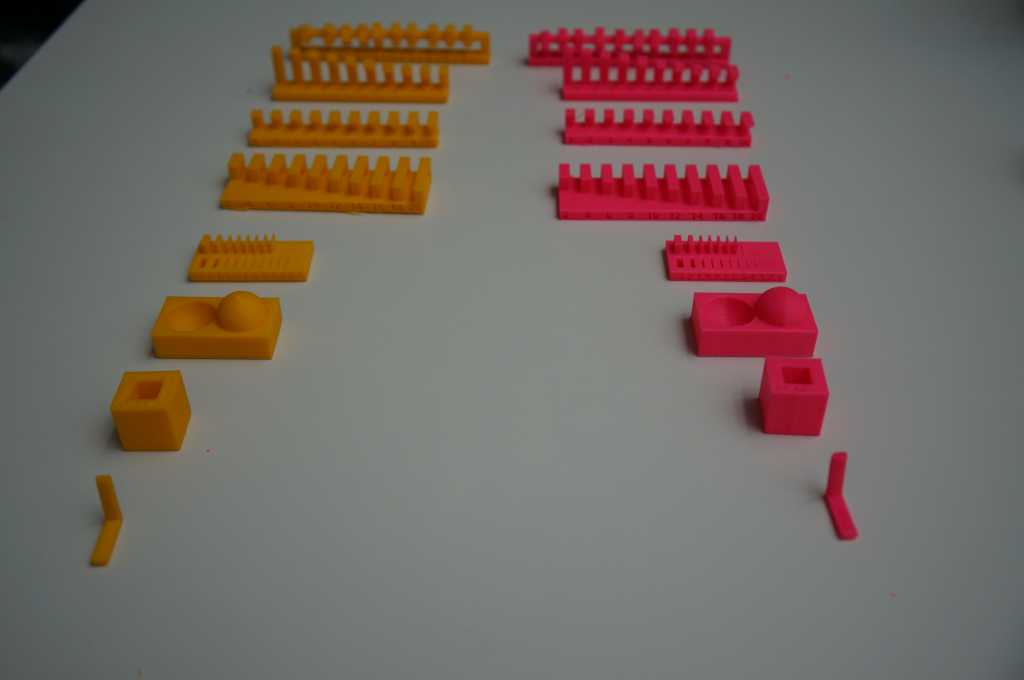
The yellow (ABS) were printed with the UP mini 2, the pink (PLA) prints were printed with the Ultimaker 2+.
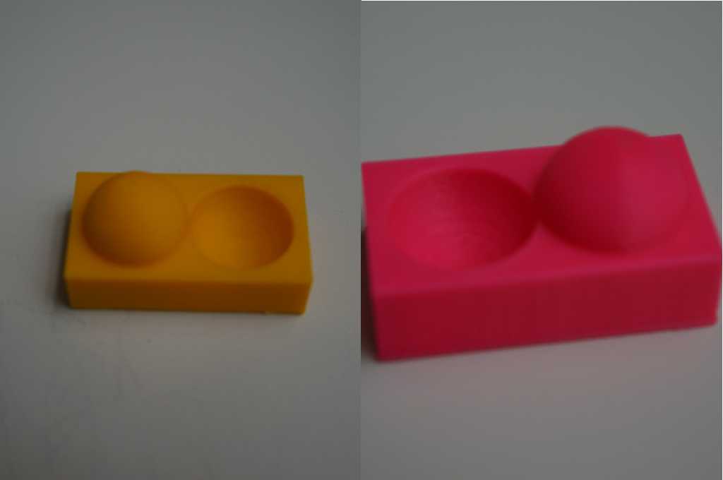
The pink (ABS) prints surface is way smoother than the yellow (PLA) one. This is not directly related to the printer settings, but rather to the material.
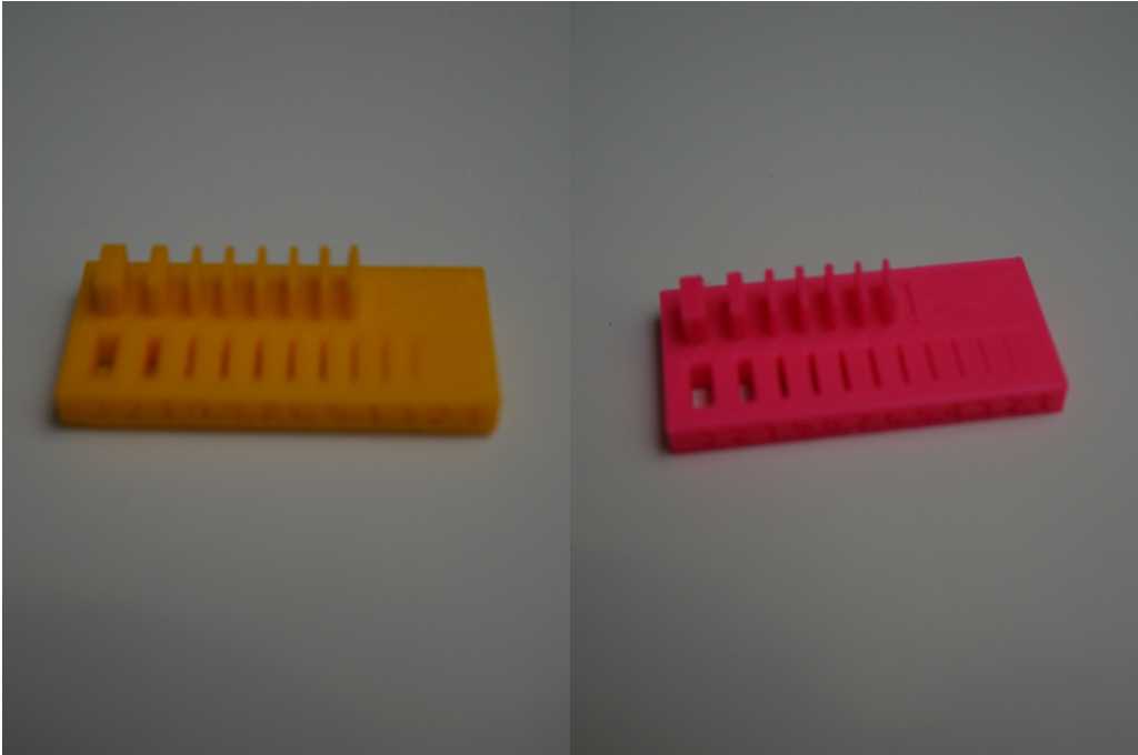
The yellow (PLA) print could create finer extrusions than the pink (ABS) one. The extrusion at 0.4mm could be completed here.
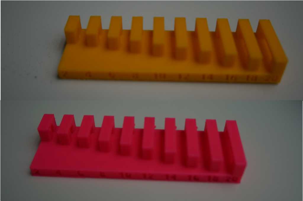
The bridging model worked well with both materials. Only the largest bridge, wich is 20mm wide, had an uneven surface on the bottom side of the bridge.
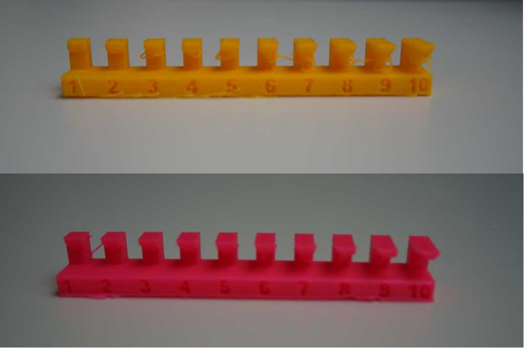
Both printers completed the overhang model, but the matieral of the bottom side of each overhang was quite fuzzy.
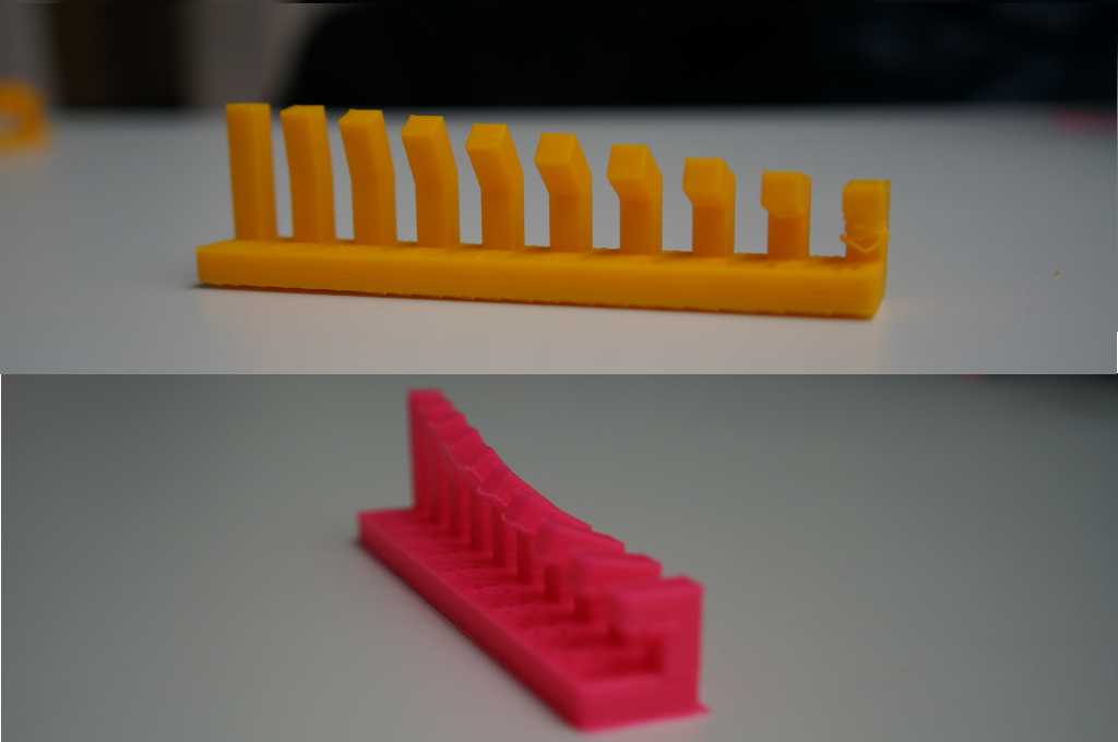
Both printers completed the angle model quite well, but the pink (ABS) print had problems with angles below 30 degrees. The yellow (PLA) print had the same problem, but with the 90° angle. The problems were the same as before with the overhang model. The bottom side got quite fuzzy.
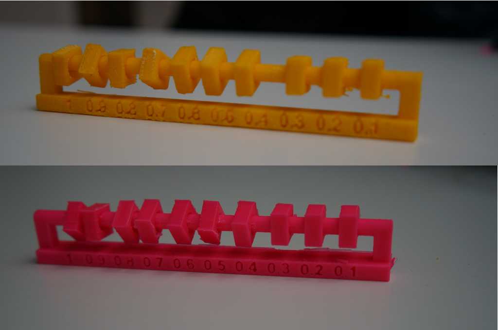
The clearance model was finished by each printer, but the pink (ABS) prints' first three elements (from the left) are easy moveable. On the yellow (PLA) print, the first six elements were moveable.
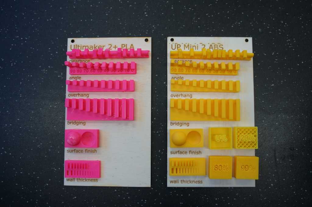
Finally, I glued the prints on lasercut pieces of wood. They will be used as exhibition pieces in the lab.
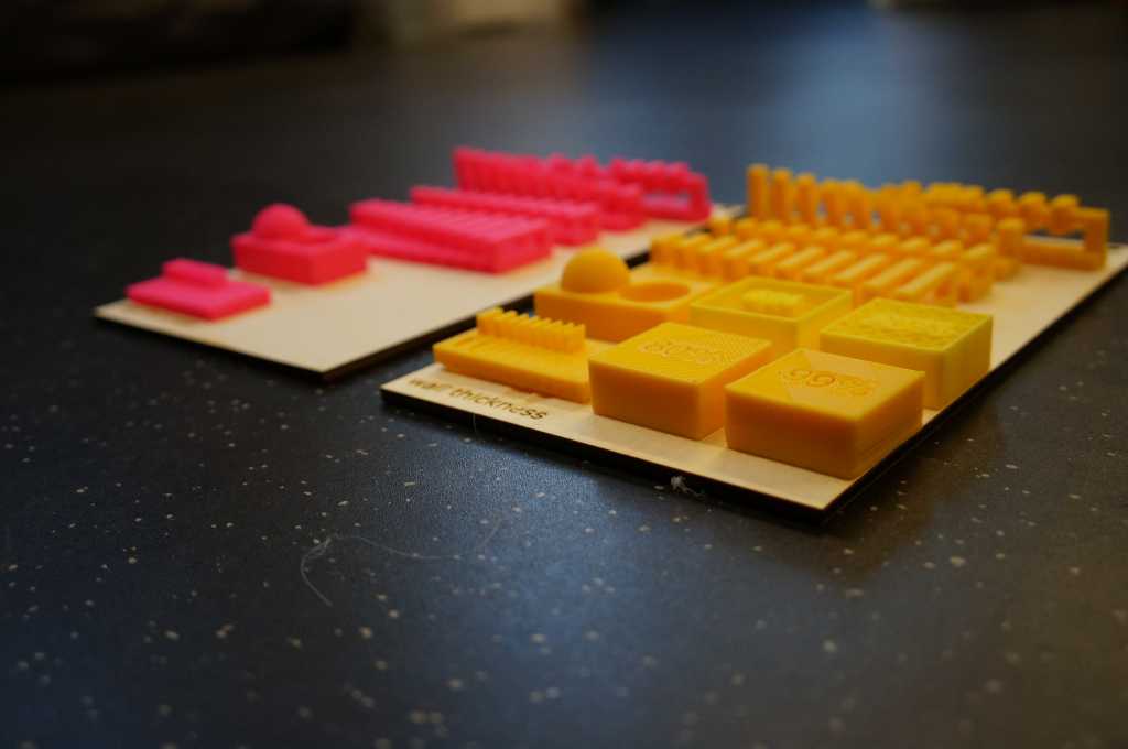
I tested different 3D printing processes and materials available at the Lab to have some exhibition pieces.
| Printer | Printing Method | Material | Material Settings | Nozzle | Layer Height | Infill | Material Flow | Weight |
|---|---|---|---|---|---|---|---|---|
| Ultimaker 2+ | FDM | Lightweight | PLA | 0,4 mm | 0,15 | 20% | 80% | 16,5g |
| UP Mini 2 | FDM | ABS | ABS | 0,4 mm | 0,15 | 20% | 100% | 24,7g |
| Ultimaker 2+ | FDM | TPU | TPU 95A | 0,4 mm | 0,15 | 20% | 100% | 19,3g |
| Ultimaker 2+ | FDM | PLA | PLA | 0,4 mm | 0,15 | 20% | 100% | 33,3g |
| Envisiontec | SLA | Photopolymer | - | - | - | 100% | - | 93,3g |
| Ultimaker 2+ | FDM | Copperfill | PLA | 0,4 mm | 0,15 | 20% | 120% | 79,0g |
| Ultimaker 2+ | FDM | Woodfill | PLA | 0,8 mm | 0,15 | 20% | 100% | 29,0g |
| Lisa Pro | SLS | PA12 | PA12 | - | - | 100% | - | 76,3g |
design and 3D print an object (small, few cm³, limited by printer time)
that could not be made subtractively
What can I do that which cannot be produced subtractively and which would still be for my final.
So maybe a movable part.
So I will design a ball which hangs in a holder and won't fall out of it.
BallAdapter
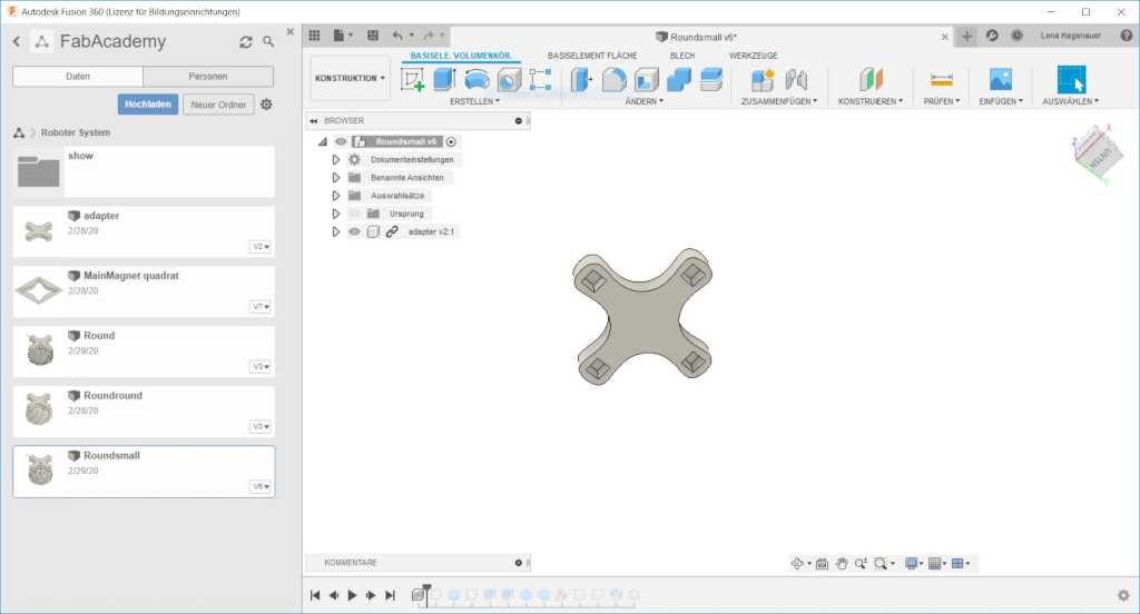
I started to design the first adapter for my Modular Robot System. First of all I designed a standard attachment which can be used for every adapter.
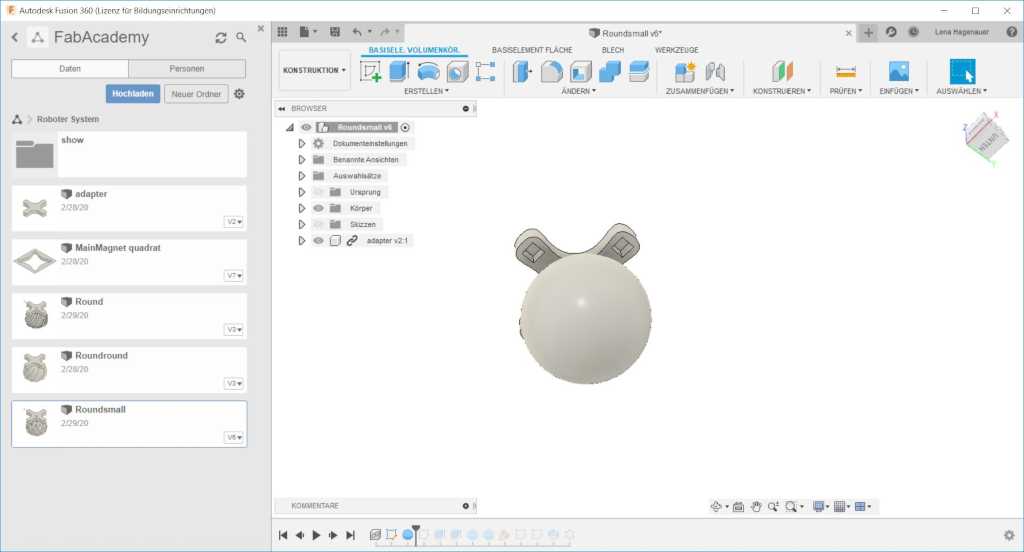
In the next step I have created a ball which should move freely.
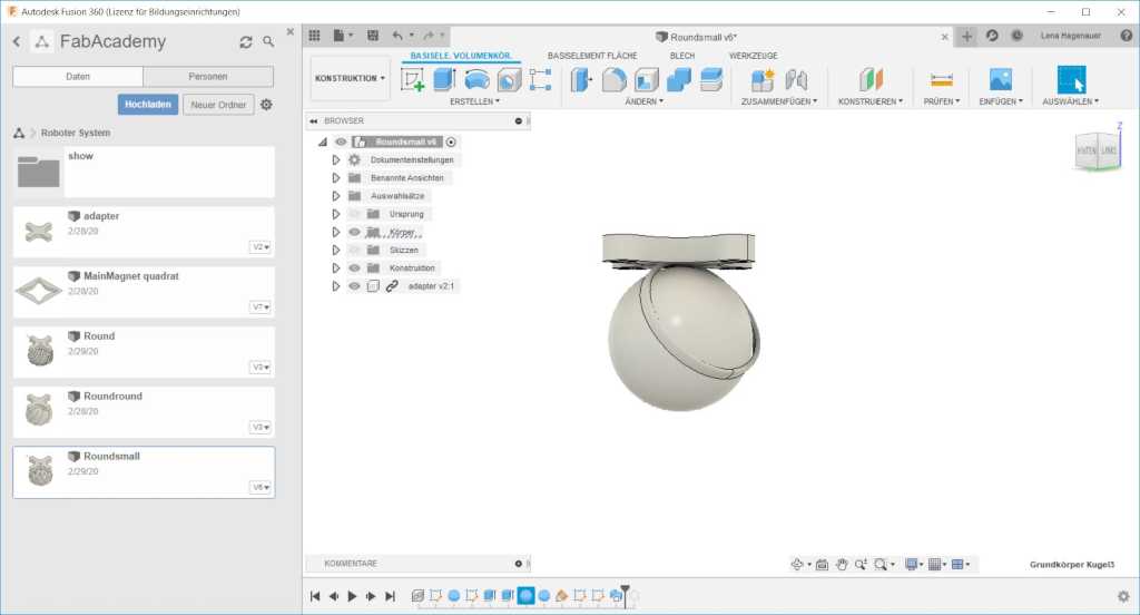
Then I created two sketches, the first to define a path, the second to define the shape of the path. The distance between the ball and the holder is 2 mm.
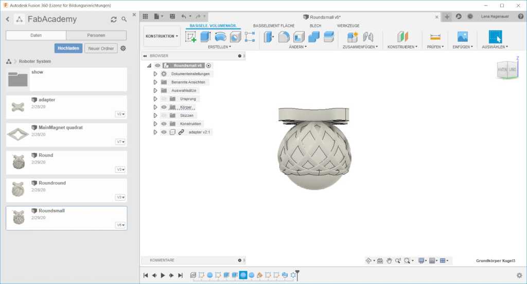
To make sure the ball is held from all sides I inserted the path several times in a round arrangement around the middle of the ball.
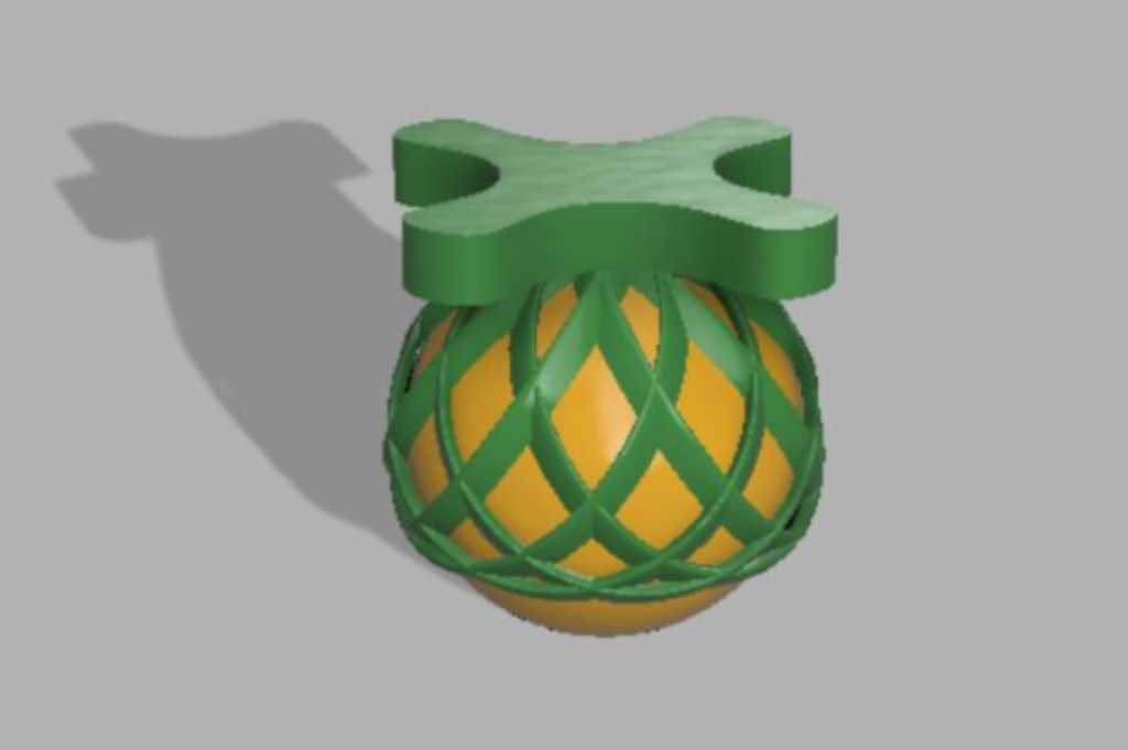
This ball adapter can be used as supportwheel for robots with only two wheels.
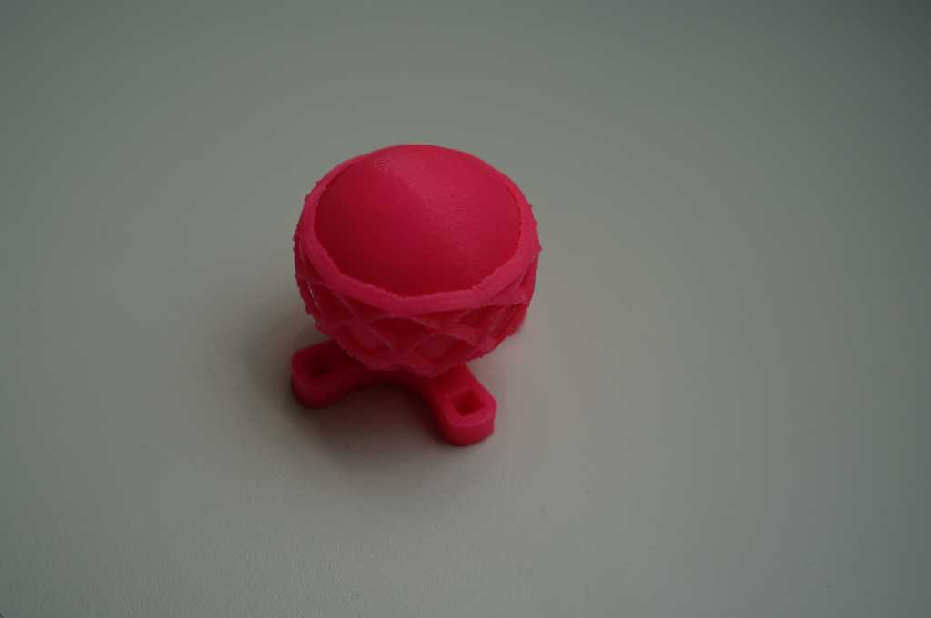
Here you can see the finished print.
To get a nice surface and to glue the parts together I put the parts in an acetone steam bath.
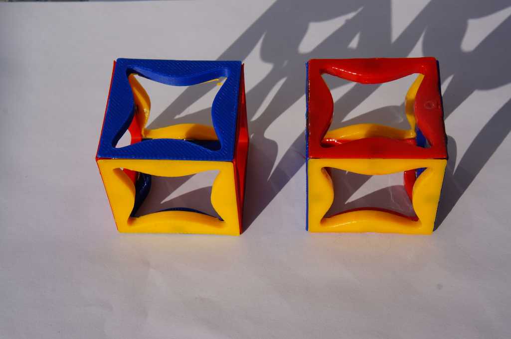
In the left picture you can see two main blocks of my modular robot system.
Left unprocessed print, right the print after the steam bath.
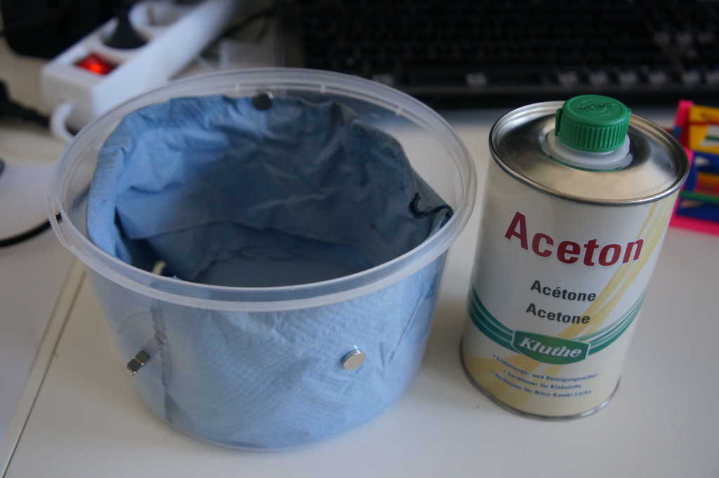
In the right picture you can see my aceton bath which consists
of a jelly baby box made of PP which is not dissolved by acetone.
I used the acetone from the Klute company. Which I bought from Hornbach.
In it I have a cloth with magnets attached which is soaked with acetone.
Afterwards I put my object on the lid of the box and put the acetone cloth over it.
After about 45 minutes I take the cube out again.
Then it holds together and has a nice surface.
3D scan an object (and optionally print it)
With the software of einscann one can make all adjustments for scanning and edit the scan.
The EinScan Pro from Shining produced better results.
Glasses
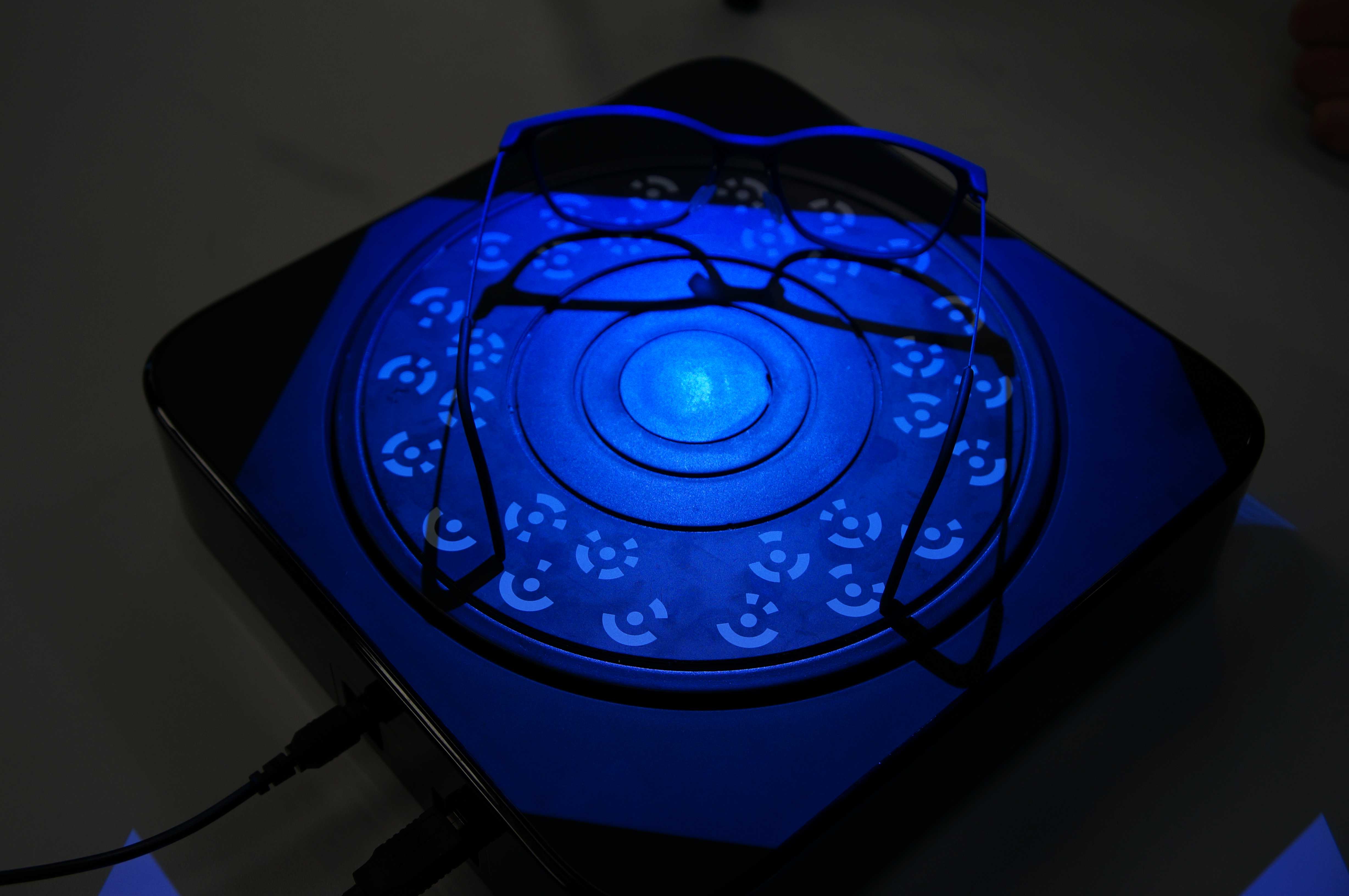
Here you can see the object I want to scan on the platform. This platform is rotatable and is controlled by the computer.
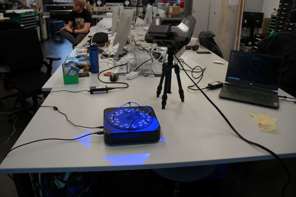
Here you can see my structure to scan. the scanner stands on a stand and is connected to the computer with an usb-cable. The object to be scanned lies on a platform which is also connected to the computer.
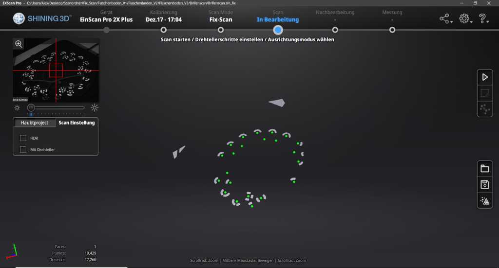
When you start the scan, the scanner illuminates the object with a certain pattern
and can warn by objet.
After that the platform turns a bit and scans again.
The sensor did not detect much as you can see in the upper left corner.
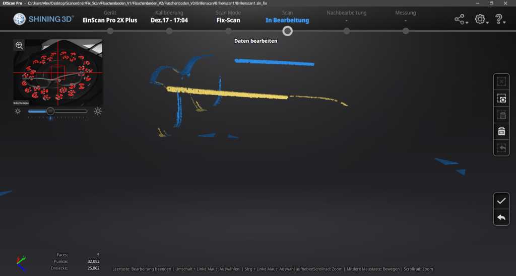
As you can see here in the picture this did not work very well.
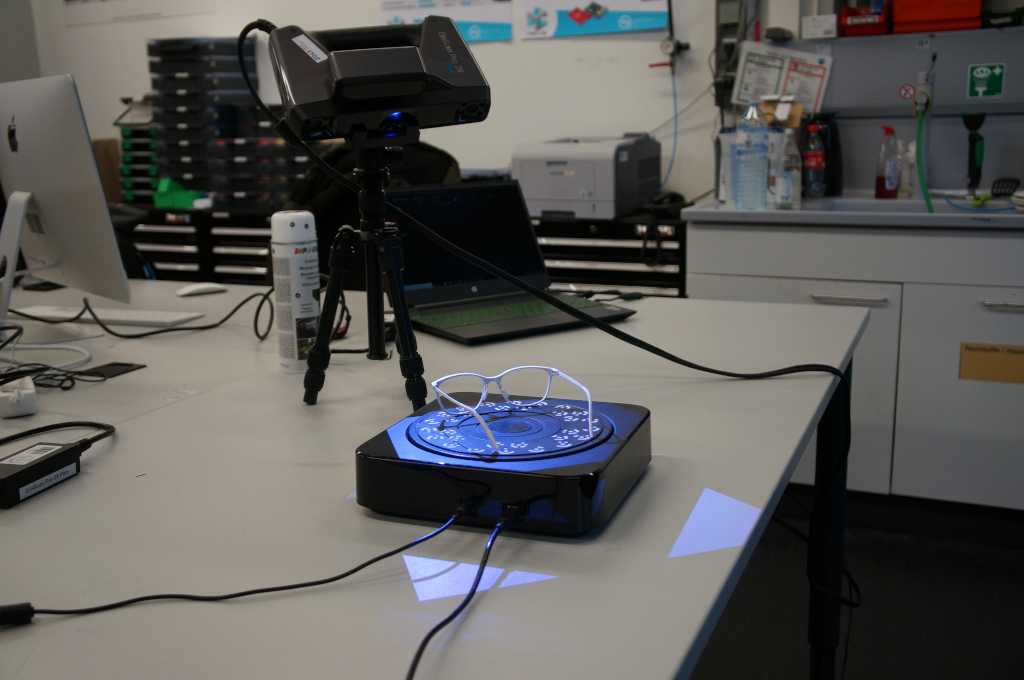
In the next step I sprayed the glasses with white chalk color, because it reflects the light better. I use chalk color from Dupli-Color I by it in a little shop near to oure Fablab.
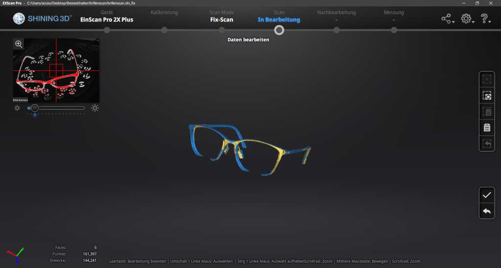
This scan looks more promising.
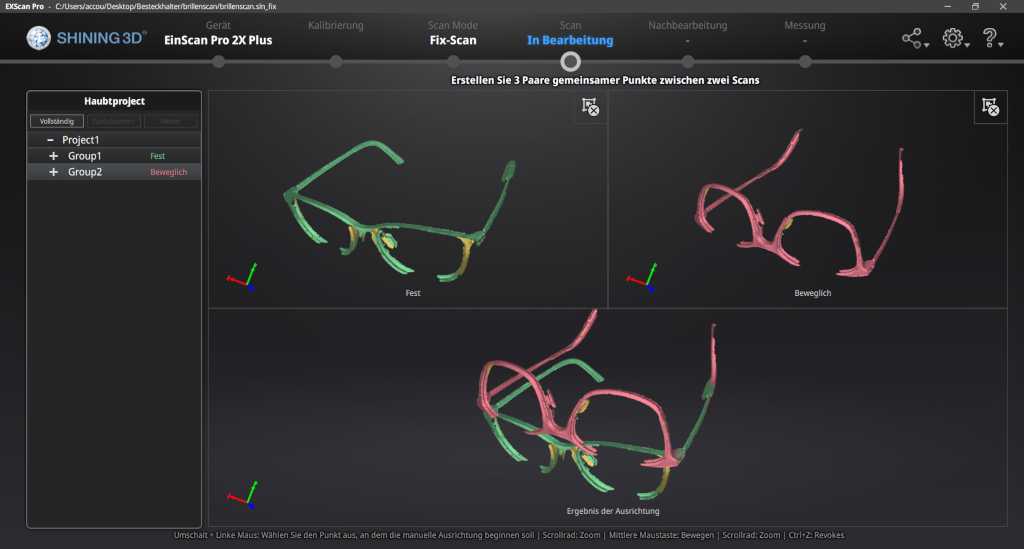
So I turned the glasses upside down so I could scan them from all sides.
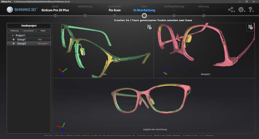
The program did not recognize how to put the two scans together, so I did it by hand.
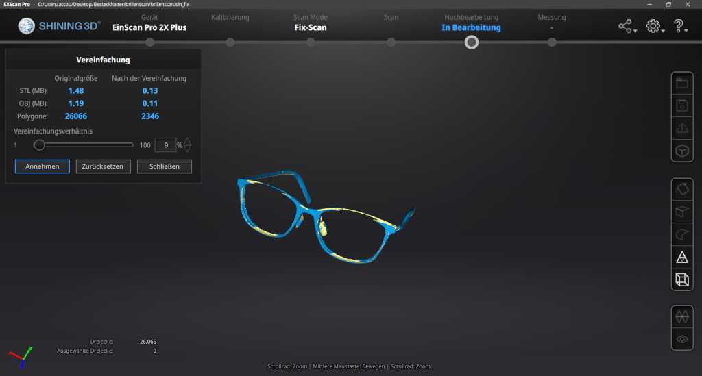
So the scan was complete. Now I have to export it for printing.
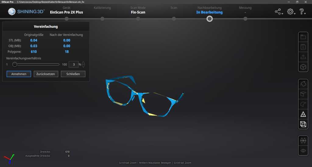
There were perhaps too few polygons.
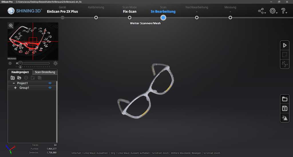
The second test scan was not perfect either. The scanner did not scan the lower sections of the glasses properly, as these are similar to the white orientation markers. I fixed this by tricking the scanner. Since I discovered that it does not scan black I put two dark USB sticks under the glasses. Then I made two more scans, this time the program scanned better and I merged them together independently. Then I printed the scan.
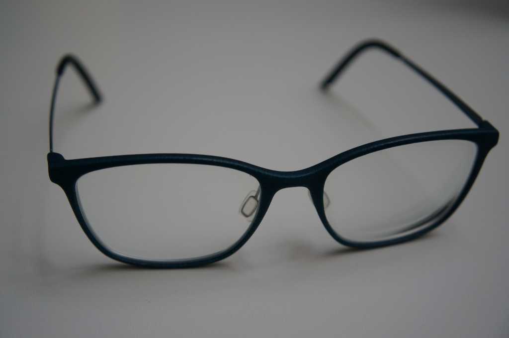
Here once again the picture of the original glasses.
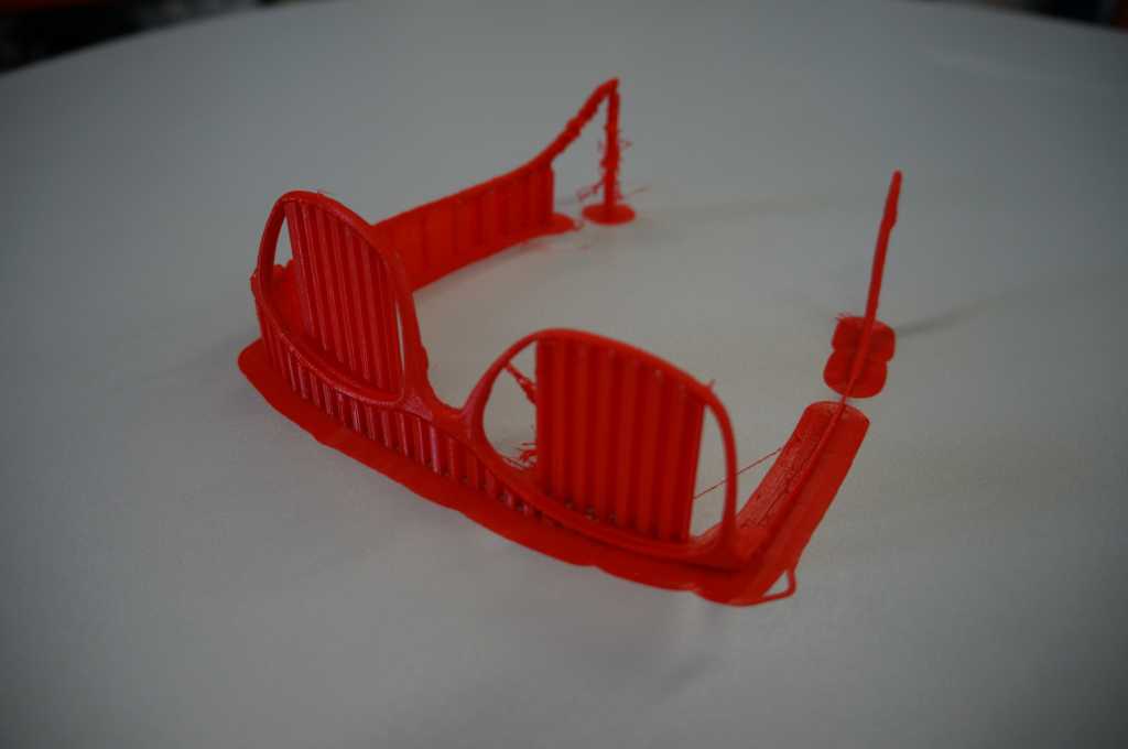
First I tried to print them out with the FDM procedure.
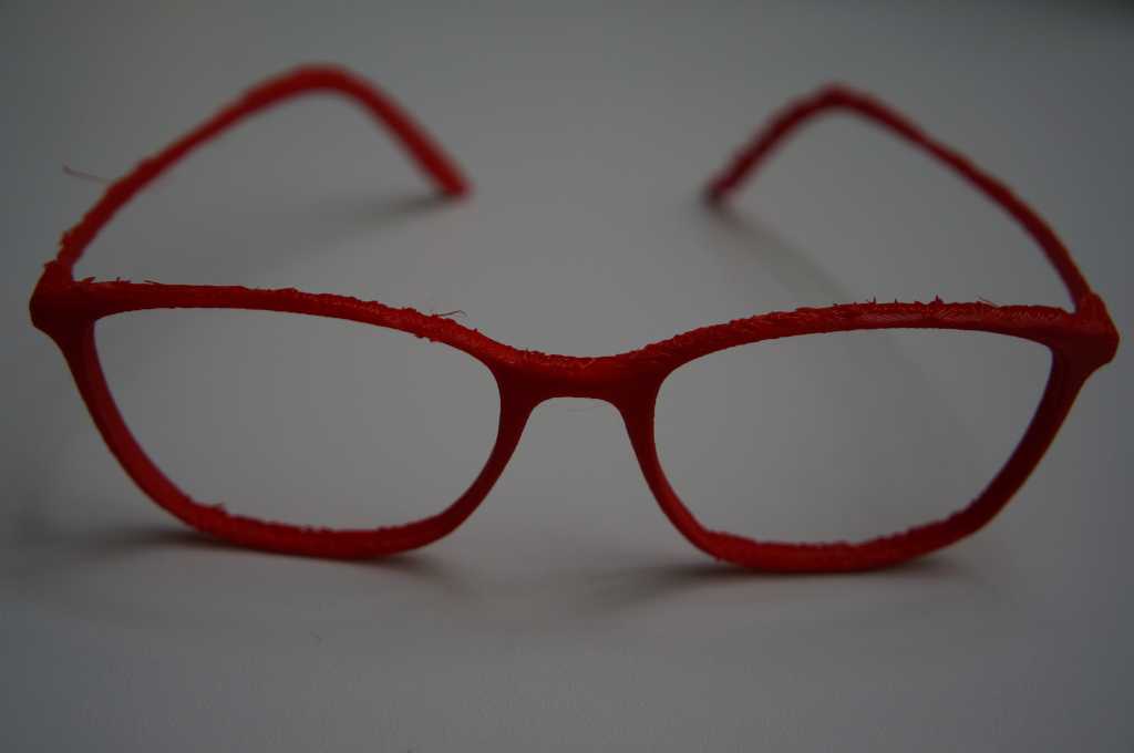
The print didn't look good.
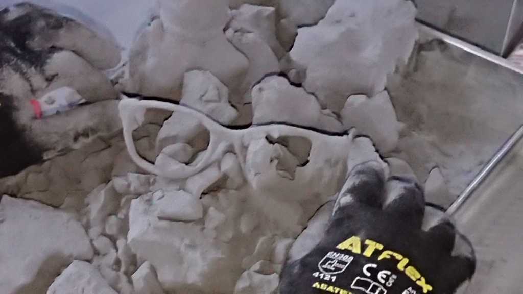
In the basement we have a SLS printer which has a much better resolution. With this I made my second print attempt.
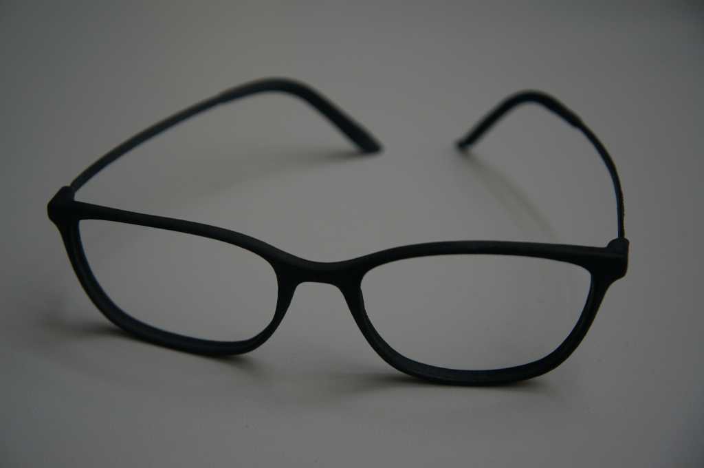
It looks pretty good and you can even use the lenses of the original glasses.
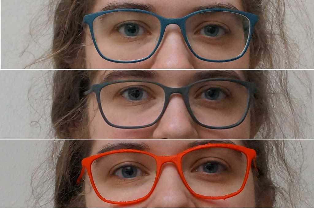
All three glasses in comparison.
This week is a robot competition in Hannover, where the team I supervise participates in the Robot Cup. Therefore I am not in the Fablab.