design, build, and connect wired or wireless node(s) with network or bus addresses
With i2c several boards can communicate with each other.
The i2c is not very fast or can transfer a lot of data or over long distances.
This does not bother us in this case because it allows us a simple communication possibility with only 4
cables.
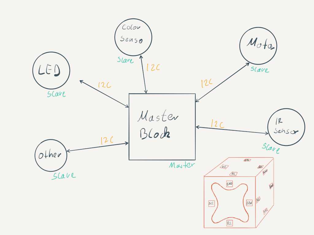
We communicate via the master slave system.
For this we need a master which controls the communication and we can have up to 112 slaves.
The slaves cannot communicate with each other but only via the master. How this works exactly I show you in the
following with code examples.
Here is an example of how a master sends a slave a night shift in the setup we first of all initialize the connection. In the Loop we start the communication and start with beginTransmission(8) where 8 is the Id of our slave. After that we can send messages with write() and when we are done we write endTransmission().
        #include

        void setup() {
          Serial.begin(9600);
          Wire.begin();
        }

        void loop() {

          Wire.beginTransmission(8);
          Wire.write("x is ");
          Wire.write(x);
          Wire.endTransmission();

          x++;
          delay(500);

        }
As with the master, we start the connection to the slave in the setup. Here we also define the ID of the slave in the brackets. Furthermore we call the Metheode onReceive(receiveEvent) which we connect to our receiveEvent. In this methode we first read the string and let it be displayed on the screen. Then we read the number and display it.
        #include

          byte SlaveReceived = 0;

          void setup() {
            Serial.begin(9600);
            Wire.begin(8);
            Wire.onReceive(receiveEvent);
          }

          void loop() {
              delay(100);

          }

          void receiveEvent(int howMany)
          {
            while(1 < Wire.available())
            {
              char c = Wire.read();
              Serial.print(c);
            }
            int x = Wire.read();
            Serial.println(x);
          }
Now how can I best integrate this into my robot system. It would be practical to have a main block with a brain and different sensor and actuator blocks. These can then simply be plugged together using the existing magnet system, which can also be used to transfer data from the I2C bus. Then the master can see what is connected and use these blocks with sensors and actuators.
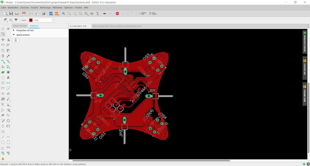
So I started designing circuit boards.
As master I will use my already created main board with the Atmega328p.
For this purpose I have designed 3 more boards for the first time.
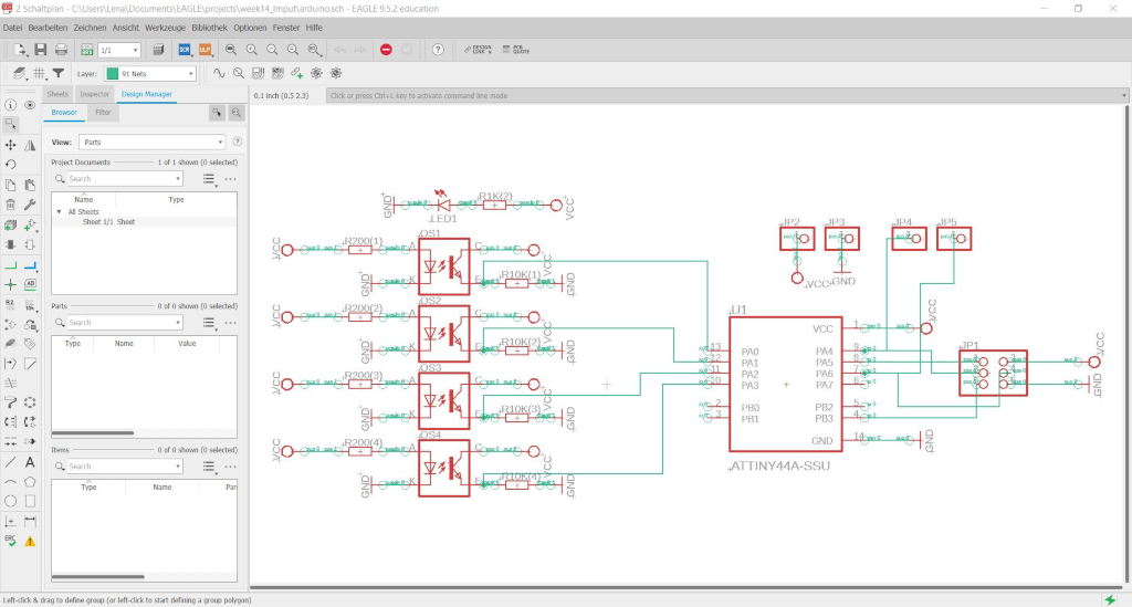
An impud device board similar to the imput board with 4 IR sensornn.
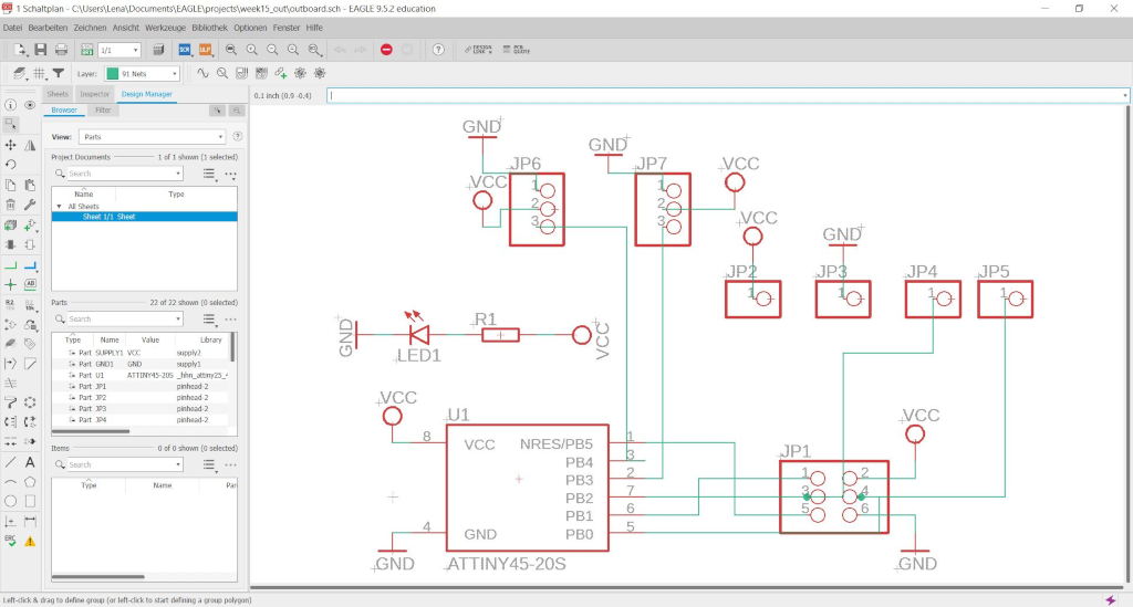
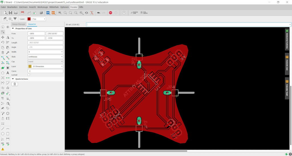
An output board with an Attyni 45 which can control 2 actuators.
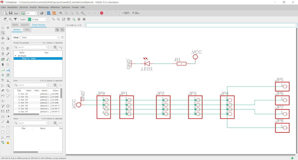
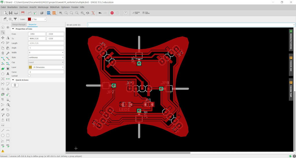
And a horn to control more I2C sensors and actuators.
| Parts | Type | Value | In Eagle |
|---|---|---|---|
| Resistor | 1206 | 10KΩ | R10(1-4) |
| Resistor | 1206 | 1KΩ | R1(2) |
| Resistor | 1206 | 200Ω | R200(1-4) |
| Resistor | 1206 | 1KΩ | R1(1) |
| LED1 | 1206 | - | LEDYELLOW |
| Pin Header 2x3 | PINHD6 | - | JP1 |
| Pin Header 1x1 | PINHD6 | - | JP2-5 |
| Attiny44 | SSU | - | Attiny44A-SSU |
| Parts | Type | Value | In Eagle |
|---|---|---|---|
| Resistor | 1206 | 1KΩ | R1 |
| LED1 | 1206 | - | LEDYELLOW |
| Pin Header 2x3 | PINHD6 | - | JP1 |
| Pin Header 1x1 | PINHD6 | - | JP2-5 |
| Pin Header 1x3 | PINHD6 | - | JP6-7 |
| Attiny45 | 20S | - | Attiny45-20S |
| Parts | Type | Value | In Eagle |
|---|---|---|---|
| Resistor | 1206 | 1KΩ | R1 |
| LED1 | 1206 | - | LEDYELLOW |
| Pin Header 1x1 | PINHD6 | - | JP5-8 |
| Pin Header 1x4 | PINHD6 | - | JP1-4,9 |
Now comes the mindbloing and mindbloing part where I lay my wires to the magnets so you just have to put the blocks together and the connection is made. I haven't found an optional solution yet but I have a first prototype. To be able to test it completely I am waiting for electronic parts which could not be delivered yet. I hope they will arrive in the next few days and I can assemble the boards.
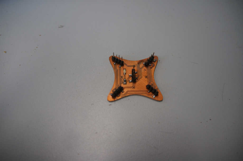
Here you can see the output board. It has 4 pins showing 4 different settings. They are the VCC, GND, SCL and SDA pins.
I have designed an adapter where the board fits exactly.
On the backside magnets are attached which touch the pins of the board and can be used as a cable dine. This board can be plugged onto the main block.
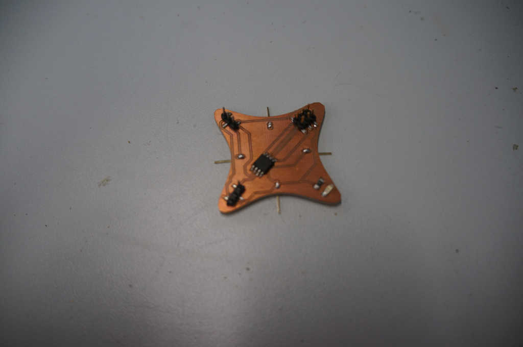
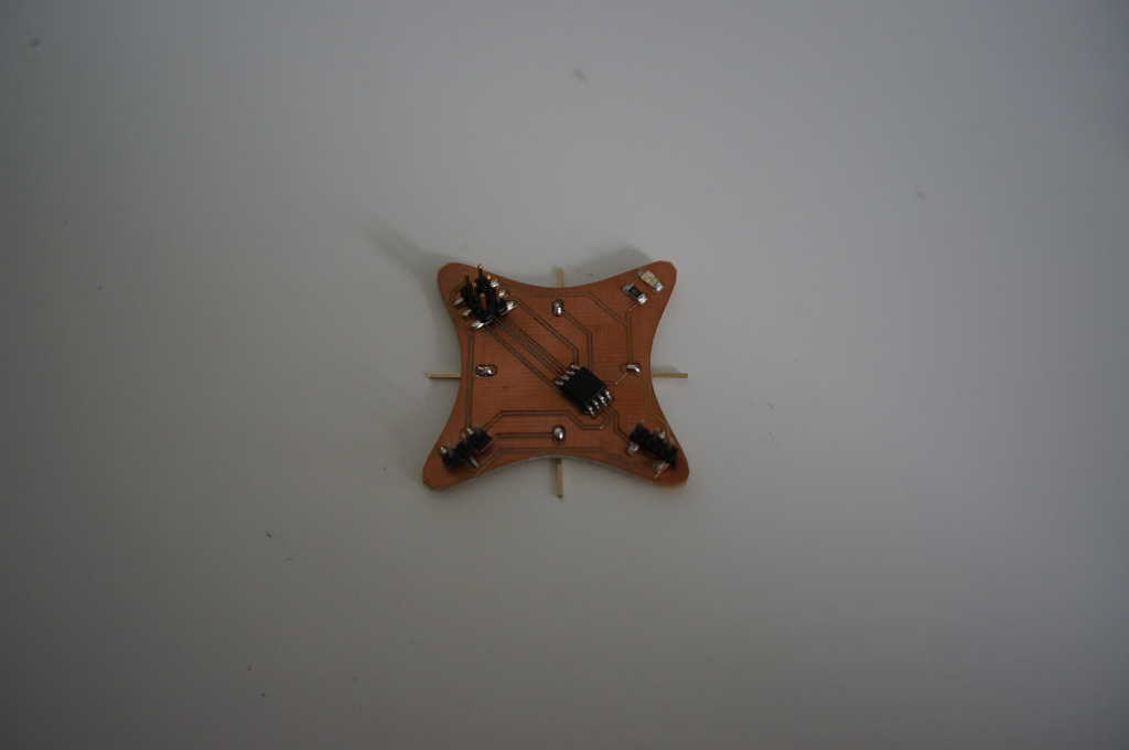
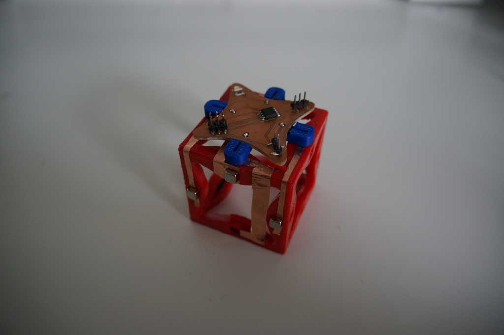
Here you can see the ePlatine which contains a 3D printed part.
After that I extended one of my blocks with copper strips to connect the connections. The version is very rough because I cut it with scissors because I don't have a plotter at home.
As soon as the 2 board is ready I will test if the data transfer works. If it works I will check the course of the data lines so that they are suboptimal.
I experimented a little bit with this variant but was not very satisfied and will have to think of something else for my final.
Of course I tested the boards anyway. I simply connected them with cables. First I wrote a 2 programms with which the boards can communicate, similar to the ones in the group assiment.
Only with another wire library because I only used Atinys and they work a little bit different.
After I programmed and wired everything I noticed that the output boards were broken somewhere because the status LED, the power supply I have on all my boards, didn't light up. I tried to fix them but I only made things worse. In the end I just tested my imput board with an Arduino which worked fine. The horn was used as a replacement in my final. Because of the multiple building of the roboeter one of the other hubs broke down.
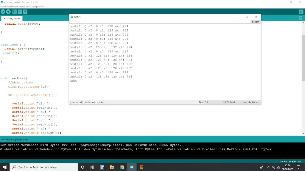
In the picture below you can see the data I receive from the 4 sensors on the serial screen.
send a message between two projects
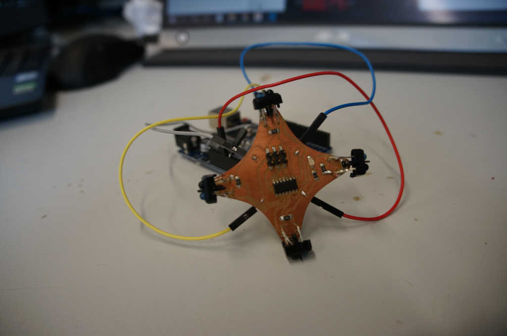
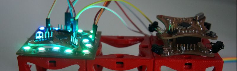
Since I am a one person group I will let communicate between my projects via i2c. I will use the Imput and thei output divice for in and output. As boards I will use the microcontroller from week 6 and the board I designed as the first prototype for the final. You can see the construction in the picture below.
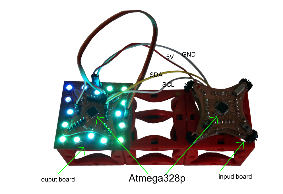
On the left board is an Atmega328p, the pin headers are designed to connect another board to it. In this case it
is the input board which is equipped with 4 infrared sensors to detect objects in the vicinity.
On the right side is again a circuit board with an Atmega328p so I have to divic my outpud divic the Led Ring.
I connected the two boards with 4 cables with one wire.
The VCC, GND, SCL and SDA pins with each other.
The 4 sensors on the left microcontroller (master) detect when an object approaches them and send this information to the slave.
The 4 sensors are read in and then mapped to the appropriate value between 0 and 127 so that they can be easily set. Then the sensor values are sent to the slave one after the other.
        void loop() {

          //read values
          readA0 = map(analogRead(A0),0,1023,0,127);
          readA1 = map(analogRead(A1),0,1023,0,127);
          readA2 = map(analogRead(A2),0,1023,0,127);
          readA3 = map(analogRead(A3),0,1023,0,127);

          //send values
          Wire.beginTransmission(8);
          Wire.write(readA1);
          Wire.write(readA2);
          Wire.write(readA3);
          Wire.write(readA4);
          Wire.endTransmission();

        }
Here you can see the modified method receiveEvent from above. The difference is that here not only one value is read in but several values are displayed one after the other on the serial monitor for control. Afterwards the read in values are calculated on the LED colors so that these red shone as soon as an object approaches them. The LEDs become redder as soon as the object is closer to you.
        void receiveEvent (int howMany){
          Serial.print("a0: ");
          int x0 = Wire.read();
          Serial.println(x0);
          readA0 = x0;

          Serial.print("a1: ");
          int x1 = Wire.read();
          Serial.println(x1);
          readA1 = x1;

          Serial.print("a2: ");
          int x2 = Wire.read();
          Serial.println(x2);
          readA2 = x2;

          int x3 = Wire.read();
          Serial.print("a3: ");
          Serial.println(x3);
          readA3 = x3;
        }
Hier you can see how it works.
Circuits
Programm idividual
Programm goup