
add an output device to a microcontroller board you've designed, and program it to do something
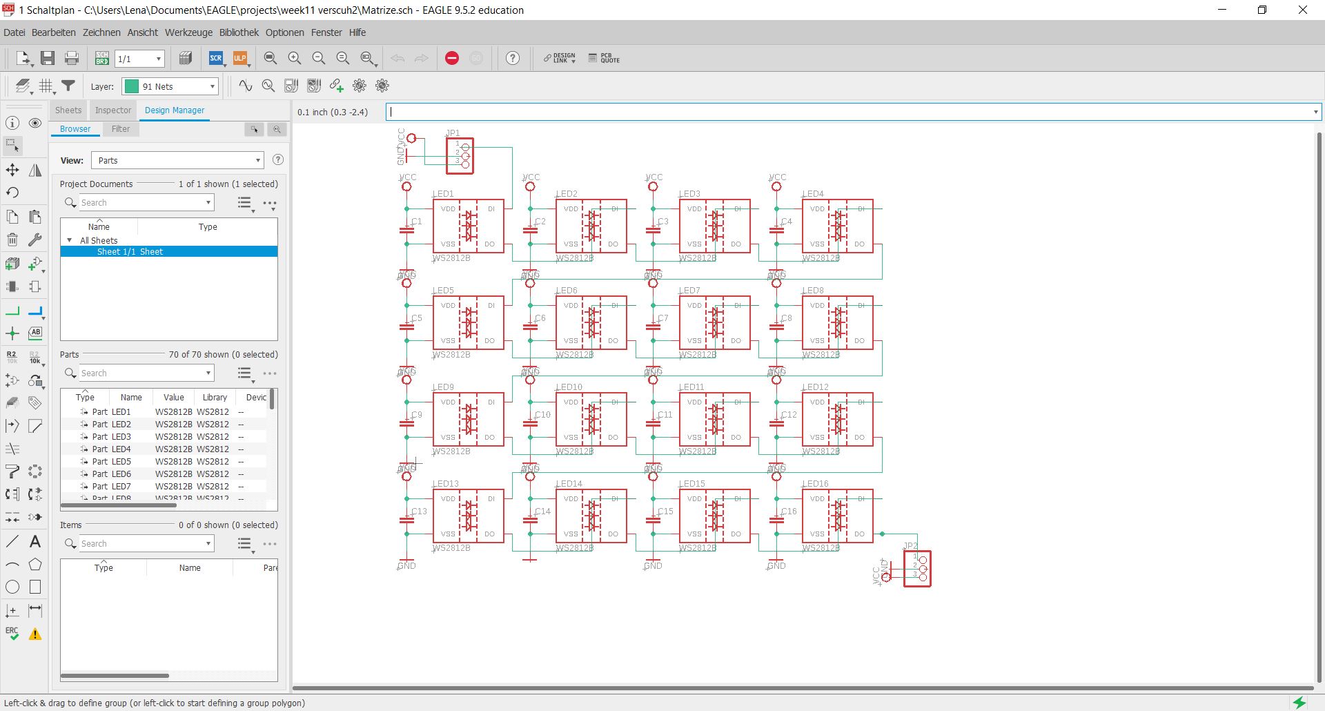
I want the first output device to deal with LEDs, more precisely with RGB LEDs (WS2812b). These LEDs have a VCC pin, a GND pin, a data in and a data out. The advantage of these LEDs is that you can connect as many as you want and control them all with only 3 pins. This is done by connecting all VCC and all GND together. Then the LEDs are connected in series, each DataOUT to DataIN.
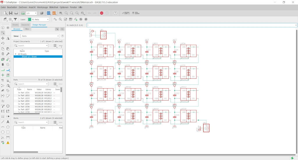
First I created the circuit in Eagle again.
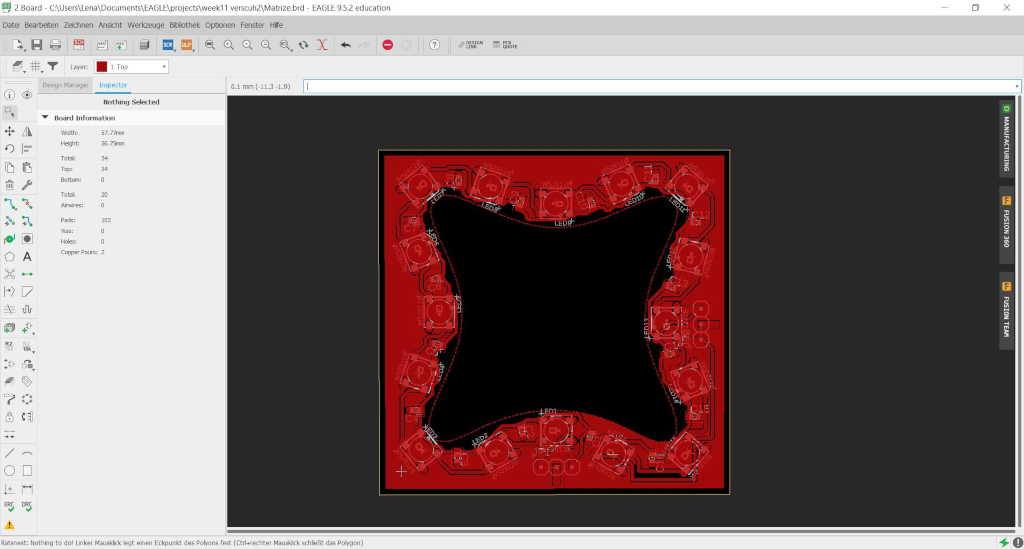
For the design I again chose my Morph3Dbot form, this time not the inner but the outer form which can be placed like a ring around the other boards.
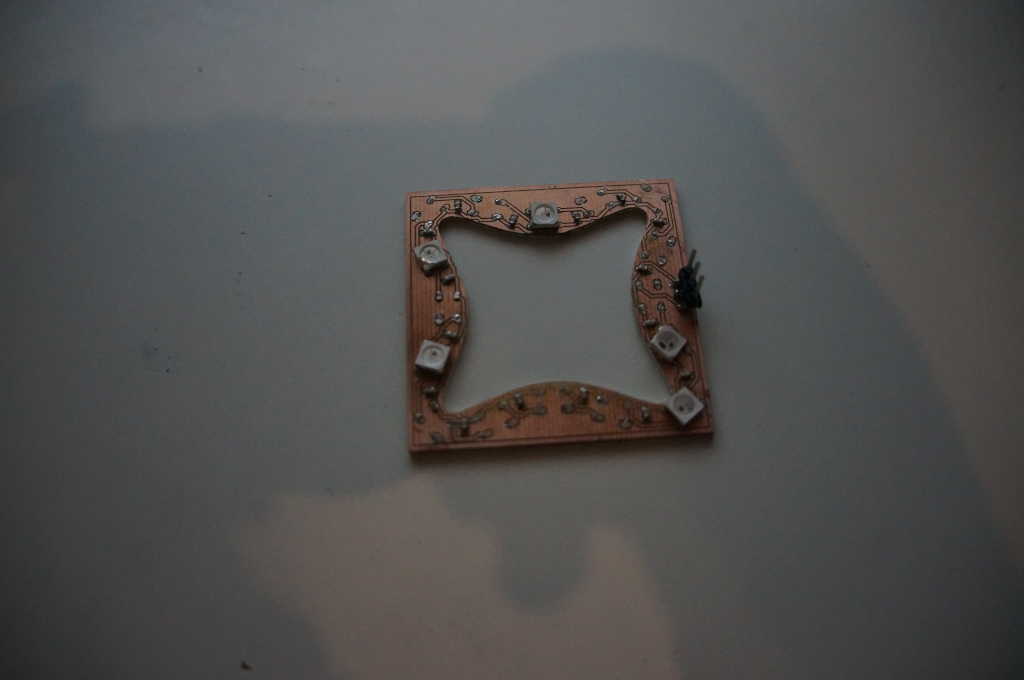
Version one went wrong. I had to unsolder
all my LEDs by hand. But what happened?
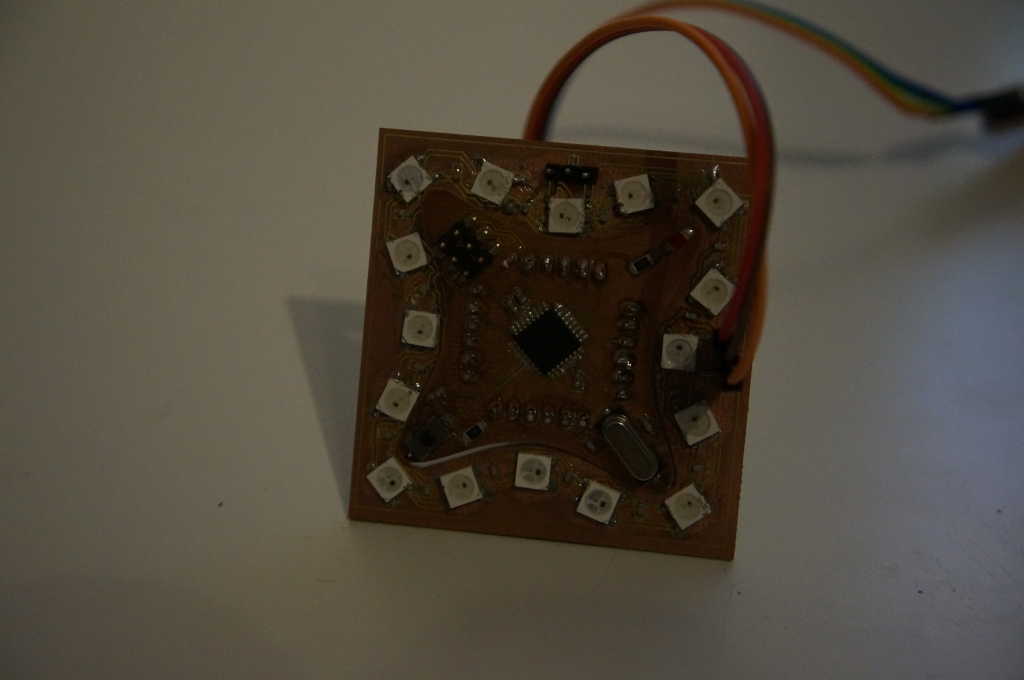
I milled the circuit board and placed the soldering paste
I used too much soldering paste and after I placed the
parts I spread the soldering paste under the LEDs and soldered things that should not be soldered.
Then I checked piece by piece all LEDs and fixed all short circuits.
Nevertheless none of the LEDs were glowing.
So I disconnected the 5V pin and only the first LED was on.
So I took a closer look at the schematic and compared it with my board.
I had mounted everything as it was shown in Eagle. Where was the error?
I had broken the LEDs. So I had a look at the datasheet of the LEDs.
I noticed that the marker for the LED was not at the same place as in
the Eagle library I downloaded from the data sheet. Instead, it is at the GND pin in the library at the VCC pin.
So I unsoldered the LED again and installed it the other way round and it lighted up.
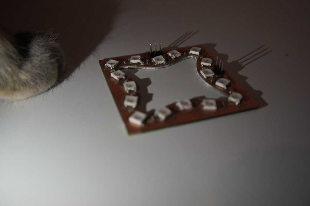
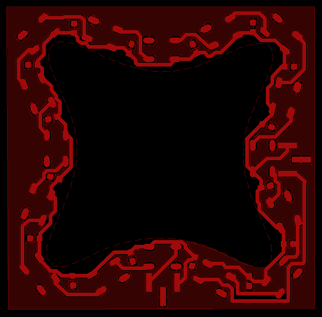
I have redesigned the VCC circuit
board again, because I had to search the VCC track
more than once to find my favourite. I made a few
small changes and made the board a little bit bigger
to get more space around the solder contacts.
Furthermore I added a two pin header which can be
connected to another board with (WS2812b) LEDs.
(And again one of my cats tried to sneak by.)
This time I soldered all LEDs individually and checked after each LED if the previous ones are still on. After a lot of time and patience I soldered all LEDs and all of them lighted up. The two boards fit very well into each other now I only have to connect the 3 pins and I can start programming.
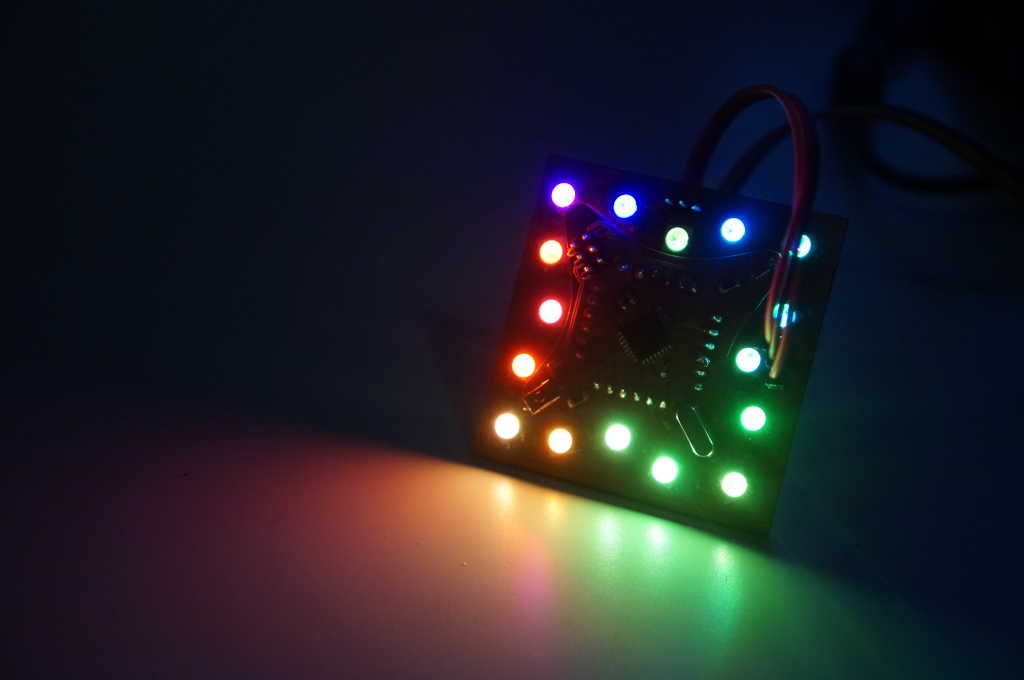
And as you can see very well, all LEDs are shining now.
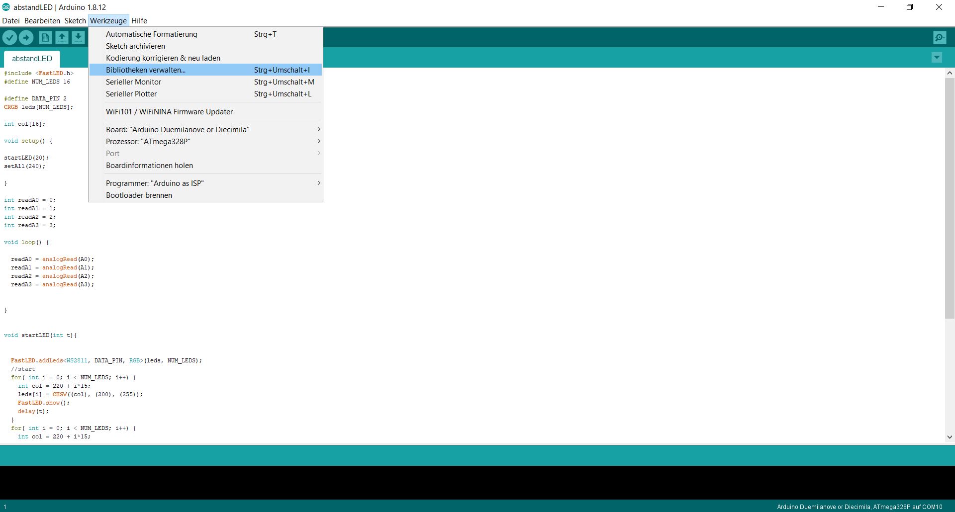
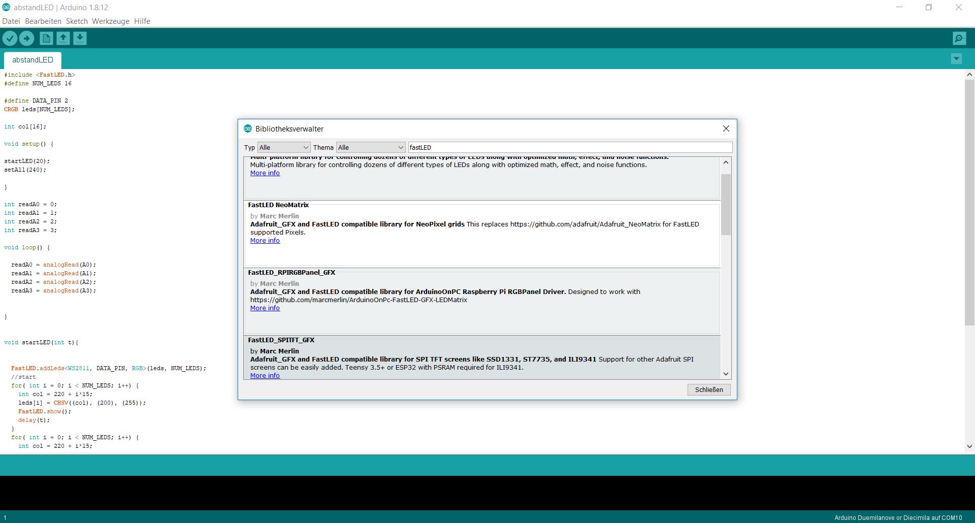
To program the LEDs I have integrated a library. There are a lot of different libraries for these LEDs, I have already tried some of them, but I prefer to work with FastLED by Daniel Garcia, since so far I've had the least problems in playing with other libraries.
To be able to use the library in a program we first have to import it with the import command. After that we can make the settings for this library. To do this we define the number of LEDs we want to program - in my case 16 - and the pin where we connect the LEDs. Finally we create an array of the typ CRGB with 16 elements in which we store the colors the LEDs should have.
          #include <FastLED.h>
          #define NUM_LEDS 16

          #define DATA_PIN 2
          CRGB leds[NUM_LEDS];
In the setup we pass our data to the class fastLED.
FastLED.addLeds(leds, NUM_LEDS);
Now I'll show one example from my program to explain roughly how to make the LEDs light up.
For this we want to let them light up one after the other in rainbow colors.
I use the HSV color space to do this.
With this, you can set 3 values for color space, saturation and brightness.
We only change the color space, the other two remain the same for now.
You can imagine the color space as a closed color circle 0 starts with
the color red and goes over orange to yellow, green, blue, purple and again red to about 200.
Now we take a look at the program excerpt below.
Since we want all 16 leds to shine in a different color we use a for-loop.
The 16 runs we have start with a color value of zero and store the color value
at the position zero in the array (leds[1] = CHSV((0), (200), (255));).
With the next command (FastLED.show();) we get the current color array output
on the leds, because we have only assigned a color to the first value and only this one is lit.
In the next run we add another LED (leds[2] = CHSV((15), (200), (255));)
but this time with a color value that is different by 15. Now we add piece by piece all the LEDs and have a
rainbow colored circle at the end.
    int col = 0;
    for( int i = 0; i < NUM_LEDS; i++) {
      col = i*15;
      leds[i] = CHSV((col), (200), (255));
      FastLED.show();
      delay(100);
    }
In the video below you can see this rainbow and some other LED experiments I have done. The source code can be found in the download section.
Of course a robot system also needs motors to move around, at best even motors with which you can build a mobile robot. So I decided to use a H-bridge for the next example. I used a bought bridge, because not all parts could be delivered for my selfmade board (due to Corona there are delivery problems).
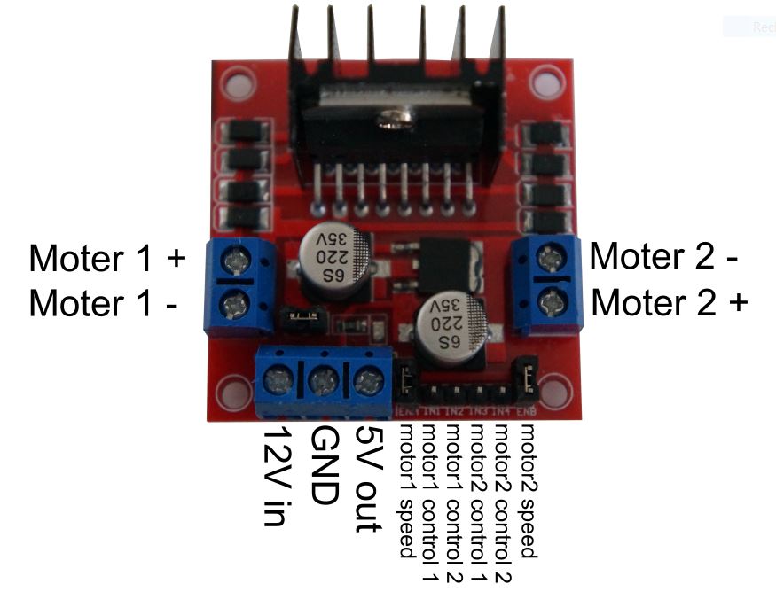
With this H-bridge it is possible to control two direct current motors.
To do this, connect the motors on the right and left to the motor + and motor -.
The external battery/power source is connected to 12V in and GND and the Arduino to 5V out and GND.
The six pins below are used to control the motors.
The outer two pins, which are bridged in this picture,
are for the speed of the motors. If the bridges are there, they run
at full power, if you connect the arduino you can control the speed with PWM pins.
To control the direction of the individual motors, det the pins connected to the Arduino to HIGH or LOW as shown
in the table below.
| Controll 1 | Controll 1 | Motor |
|---|---|---|
| LOW | LOW | stop |
| HIGH | LOW | Forward |
| LOW | HIGH | Backward |
| HIGH | HIGH | dont do this |
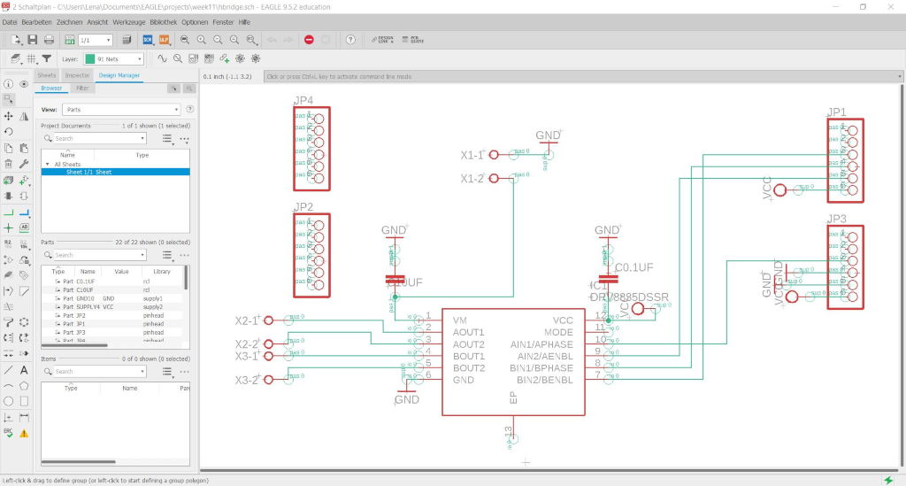
I have already made a drawing in Eagle for my bridge although not all my parts are there yet.
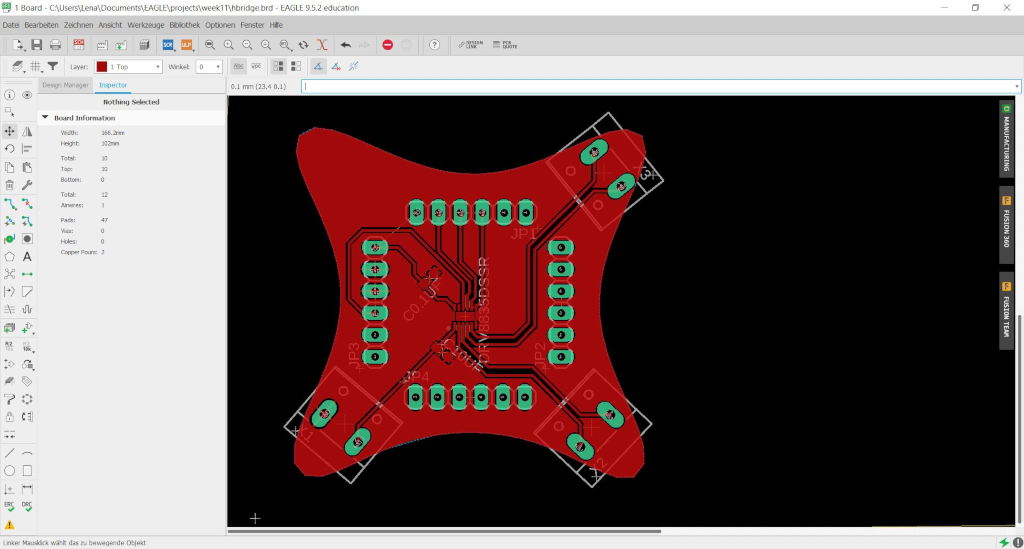
It's plugged back into my motherboard. The IC for the H-Bridge is very small and I hope I can solder it to the board. But it was the only one deliverable in a reasonable time.
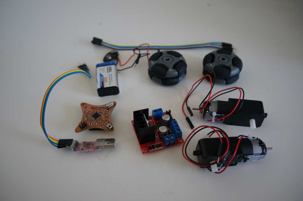
The first test was done with a purchased H-bridge. For this I have picked out all parts: A bridge, my circuit board, a 9V battery, the programmer, two motors and two wheels.
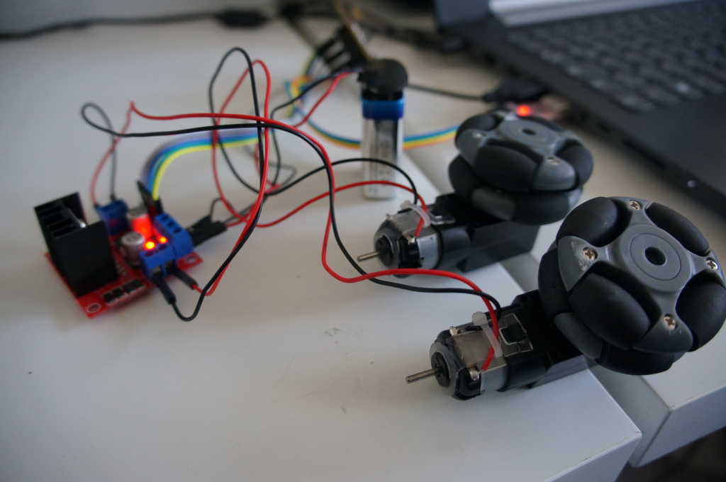
After that, I put everything together.
First I created two arrays in which I store my motor pins. I did this to make the access to them easier.
          //Motor 1 -> 10,9 speed -> 11
          //Motor 2 -> 8,7 speed -> 6
          int motor[4] = {10,9,8,7};
          int sped[2] = {11,6};
In setup I define all pins I want to use as outputs.
Afterwards I wrote some methods to make it easier for me to control a mobile robot with two wheels.
          //set speed for motor n with value s
          void setSpeet(int n,int s){
            analogWrite((sped[n]),s);
          }

          //set speed for all motors with value s
          void setSpeedAll(int s){
            for( int i = 0; i  <2; i++){
              setSpeet(i,s);
            }
          }


          // turn motor n forward
          void vw(int n){
             digitalWrite(motor[n*2], LOW);
             digitalWrite(motor[n*2+1], HIGH);
          }

          //turn motor n backwards
          void rw(int n){
             digitalWrite(motor[n*2], HIGH);
             digitalWrite(motor[n*2+1], LOW);

          }

          // stop Motor n
          void st(int n){
             digitalWrite(motor[n*2], LOW);
             digitalWrite(motor[n*2+1], LOW);

          }

          //stop all motors
          void stopall(){
            for( int i = 0; i  <2; i++){
              st(i);
            }
          }
measure the power consumption of an output device
To increase the power consumption and to measure the power, I have to go into our fablab because the power suplies are built into the tables and I can't take them home with me.
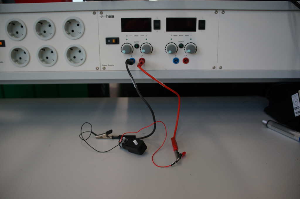
Here you can see our hera tables. There you can connect two cables (VCC and GND) and then you can adjust the amps and volts on the wheels on the top.
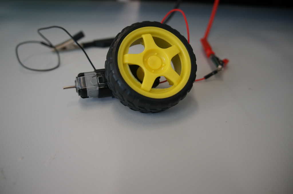
I have connected a gear motor and to visualize the direction the motor is rotating, I also connected a wheel.
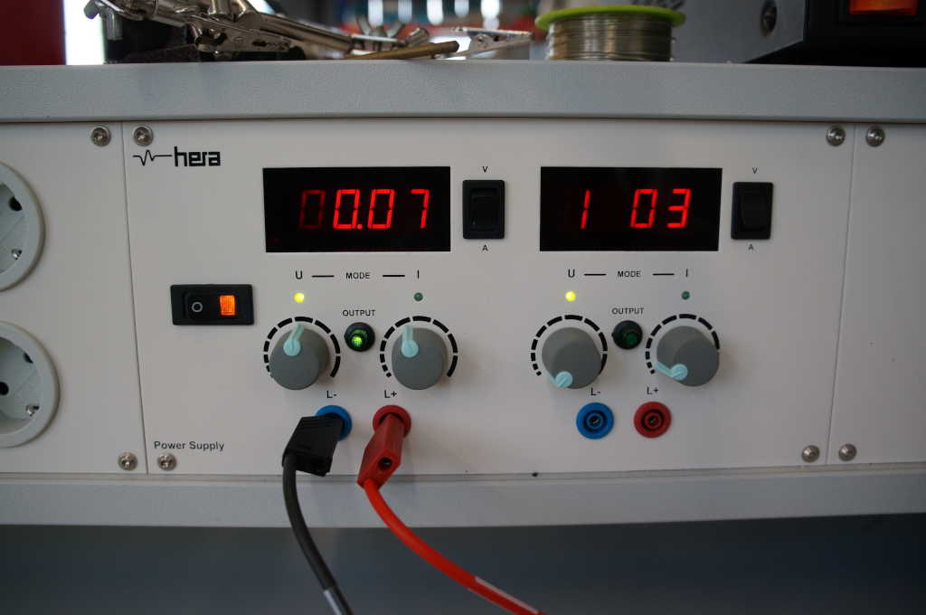
The motor needs about 0.07 amps.
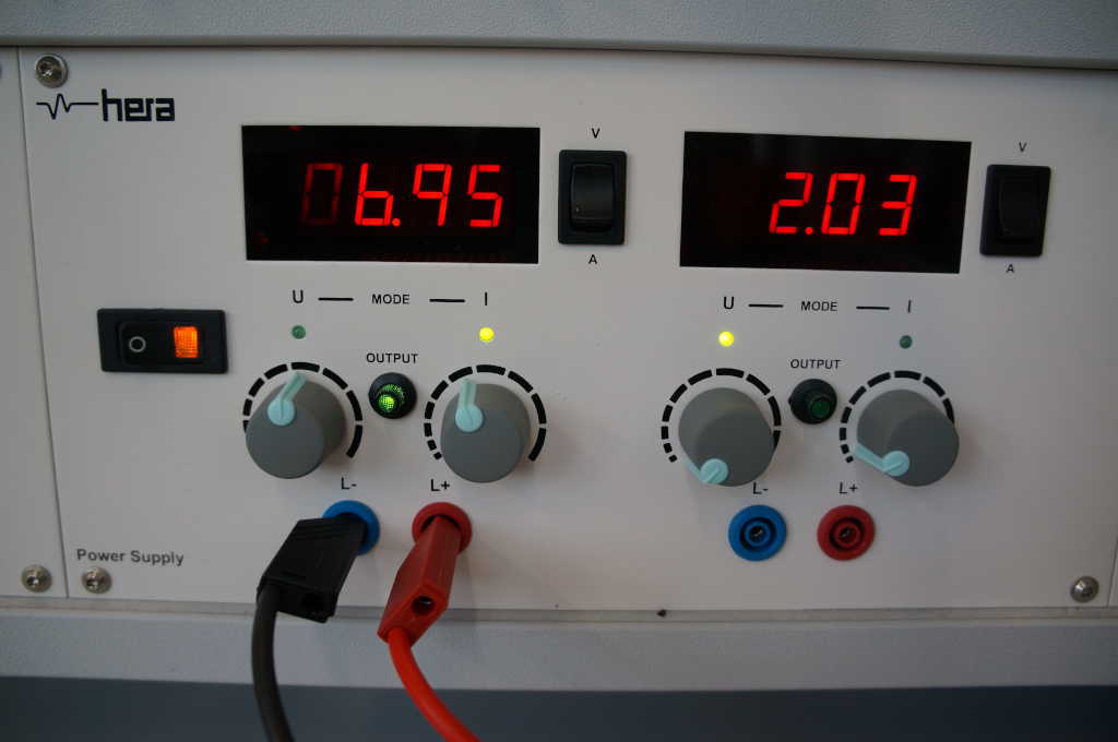
The motor needs about 7 volts.