Individual Assignment
- Add an output device to a microcontroller board you've designed and program it to do something.
Learning Outcomes
- Demonstrate workflows used in controlling an output device(s) with MCU board you have designed.
Progress Status – Output Devices Experiments
Development and testing of output devices using a custom ESP32-C3 PCB.
PWM-based control of a servo motor with real-time angle feedback using joystick input.
Graphical visualization of servo angle using an SSD1306 display with a dynamic analog-style gauge.
Sound generation using PWM, where joystick input controls tone frequency to produce musical notes.
System Overview – Output Devices Integration
This assignment focuses on exploring how a microcontroller can control and drive different types of output devices. Using the same custom PCB designed in a previous week, based on the XIAO ESP32-C3, multiple output components were integrated to generate physical responses from digital signals.
The system includes three main types of outputs: an actuator (servo motor), a visual interface (SSD1306 OLED display), and an audio output (passive buzzer). Each device requires a different control strategy, allowing the exploration of multiple signal generation techniques such as PWM, digital communication, and graphical rendering.
System Workflow
The system follows a structured interaction flow:
- Input: user interaction through joystick (position control)
- Processing: signal interpretation and mapping inside the microcontroller
- Output: actuation, visualization, and sound generation
The joystick input is processed by the microcontroller and translated into different output behaviors. The servo motor responds by changing its angular position using PWM, the OLED display provides real-time graphical feedback, and the buzzer generates sound frequencies based on the input signal.
This architecture demonstrates how a single microcontroller can coordinate multiple output devices simultaneously, each with different electrical and communication requirements, while maintaining a unified interaction model.
All experiments were implemented on the same hardware platform, reusing the custom PCB developed in Week 08, which enables a modular and scalable approach for integrating both input and output systems.
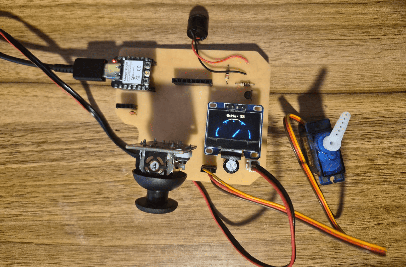
Complete system setup showing the custom PCB, XIAO ESP32-C3, and integrated output devices: servo motor, OLED display, and buzzer.
Simulation Validation – Wokwi
Before implementing the circuits on physical hardware, all experiments were first simulated using Wokwi. This allowed me to validate both the code logic and the behavior of the output devices in a controlled environment.
Through simulation, I was able to perform early debugging, verify pin configurations, and test different control strategies such as PWM signals for the servo motor and buzzer, as well as I2C communication for the OLED display.
This approach significantly reduced development time and minimized the risk of hardware errors, such as incorrect wiring or unstable signal behavior. It also provided a better understanding of how different output devices respond to microcontroller commands.
Using simulation as a first step helped ensure that each output device behaved correctly before integrating it into the final physical system based on the custom PCB.
Experiment 1 – Servo Motor Control (PWM Output)
In this experiment, a servo motor was used as an output device to demonstrate how a microcontroller can control mechanical motion using PWM (Pulse Width Modulation) signals. The system allows controlling the angular position of the servo using a joystick as input.
A servo motor is a closed-loop control system that integrates a DC motor, a position sensor, and a control circuit. Unlike a standard DC motor, a servo does not rotate freely, but instead moves to a specific angular position (typically between 0° and 180°) based on the input signal.
PWM Control Principle
The position of the servo is controlled using a PWM signal with a fixed frequency (typically 50 Hz). This means that a pulse is generated every 20 ms. The key parameter is the pulse width:
- ~1 ms → 0°
- ~1.5 ms → 90°
- ~2 ms → 180°
In the ESP32-C3, PWM is generated using the LEDC module, where the resolution defines how finely the duty cycle can be adjusted. In this case, a 12-bit resolution is used, allowing values from 0 to 4095.
Power Considerations
Servo motors require significantly more current than the microcontroller can provide. For this reason, the servo was powered using an external 5V power supply (1.3A), while sharing a common ground with the ESP32-C3.
This prevents voltage drops, unstable behavior, or potential damage to the microcontroller.
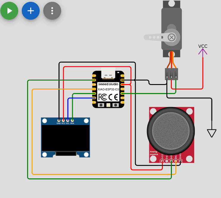
Servo motor control using PWM signal and external power supply (Wokwi simulation).
Circuit Connection
- Red → 5V (external power supply)
- Brown/Black → GND (common ground)
- Yellow → D9 (PWM signal)
- VCC → 3.3V
- GND → GND
- X Axis → D2 (ADC input)
- VCC → 3.3V
- GND → GND
- SDA → D4
- SCL → D5
Program Code
#include <Adafruit_GFX.h>
#include <Adafruit_SSD1306.h>
#include <Wire.h>

#define SDA   D4
#define SCL   D5
#define servo D9
#define potX  D2

#define height 64
#define width 128
#define rst    -1

Adafruit_SSD1306 display(width, height, &Wire, rst);

int thita = 0;
int midPoint = 2048;

void setup() {
  ledcAttach(servo, 50, 12); // PWM: 50Hz, 12-bit resolution

  Serial.begin(115200);
  Wire.begin();

  if(!display.begin(SSD1306_SWITCHCAPVCC, 0X3C)){
    Serial.println("Oled Display NOT Found...");
    for(;;);
  }

  displayTxtConfig(2, 15, 0);
  display.clearDisplay();
  display.println("Servo Motor");
  displayTxtConfig(2, 40, 30);
  display.println("Control");
  display.display();

  delay(3000);
}

void loop() {

  int value = analogRead(potX);

  if(value - midPoint > 100){ thita += 1; }
  if(value - midPoint < -100){ thita -= 1; }

  if(thita < 0){ thita = 0; }
  if(thita > 180){ thita = 180; }

  moveServo();
  displayAngle();
}

void displayTxtConfig(int size, int x, int y){
  display.setTextSize(size);
  display.setTextColor(WHITE);
  display.setCursor(x, y);
}

void displayAngle(){
  display.clearDisplay();
  displayTxtConfig(2,10,50);
  display.print("Thita=");
  display.print(thita);
  display.print("°");
  display.display();
}

void moveServo(){
  int duty = map(thita, 0, 180, 102, 512);
  ledcWrite(servo, duty);
}
Code Explanation
-
PWM Generation using LEDC Module:
The ESP32-C3 generates PWM signals using the LEDC hardware peripheral.
The function
ledcAttach(servo, 50, 12)configures the PWM signal with a frequency of 50 Hz and a resolution of 12 bits. A frequency of 50 Hz corresponds to a period of 20 ms, which matches the control requirements of standard hobby servos. The 12-bit resolution allows the duty cycle to be represented with 4096 discrete levels (0–4095), enabling fine control over pulse width and therefore precise angular positioning. -
Servo Control via Pulse Width Modulation:
Unlike typical PWM applications where duty cycle controls power, in servos
the duty cycle encodes position. The servo interprets the duration of the
HIGH pulse within each 20 ms period:
- Short pulse (~1 ms) → minimum angle (0°)
- Medium pulse (~1.5 ms) → center position (90°)
- Long pulse (~2 ms) → maximum angle (180°)
moveServo()converts the desired angle into a duty cycle usingmap(). The selected range (102–512) corresponds to pulse widths suitable for the servo when using 12-bit resolution at 50 Hz. -
Analog Input Interpretation (Joystick):
The joystick provides an analog voltage that is read using
analogRead(), producing a value between 0 and 4095 (12-bit ADC). Instead of directly mapping this value to an angle, the system implements a relative control strategy based on deviation from a calibrated midpoint (midPoint = 2048). This is necessary because the joystick mechanically returns to its center position. -
Threshold-Based Movement (Noise Filtering):
A threshold of ±100 is applied when comparing the joystick reading with
the midpoint. This prevents small fluctuations (noise) from causing
unintended servo movement.
Only when the deviation exceeds this threshold, the angle variable
thitais incremented or decremented. This results in a stable and smooth control behavior. -
Incremental Position Control:
The servo angle is not set directly from the joystick value. Instead,
the variable
thitais updated incrementally (+1 or -1). This creates a velocity-like control model, where the joystick determines the direction of movement rather than the absolute position. This approach improves user control and avoids abrupt jumps in servo position. -
Angle Constraint:
The value of
thitais limited between 0 and 180 degrees using conditional checks. This ensures that the generated PWM signal always remains within the valid operating range of the servo, preventing mechanical stress or undefined behavior. -
OLED Display Rendering:
The display is controlled via I2C using the SSD1306 driver.
Each frame is generated by clearing the display buffer
(
clearDisplay()), writing new data, and then updating the screen usingdisplay(). This buffered rendering approach avoids flickering and ensures smooth visualization of the servo angle in real time. -
System Integration:
The program integrates three subsystems:
- Analog input (joystick)
- Signal processing (angle calculation and mapping)
- Output devices (servo actuation and OLED feedback)
loop()function continuously executes this cycle, creating a real-time interactive system where user input directly affects physical motion and visual output.
System Validation – Simulation vs Physical
Wokwi simulation showing PWM control of the servo.
Physical implementation using external 5V power supply.
Experiment 2 – OLED Display (Graphical Output Interface)
In this experiment, an SSD1306 OLED display was used to create a graphical interface that visualizes the angular position of the servo motor. Instead of displaying only numeric values, a dynamic analog-style gauge (galvanometer) was implemented.
OLED Display Fundamentals
The OLED display used in this project has a resolution of 128x64 pixels, meaning it consists of a matrix of 128 columns and 64 rows. Each pixel represents an individual light-emitting element that can be turned ON or OFF independently.
The coordinate system starts at the top-left corner (0,0). The X-axis increases to the right, while the Y-axis increases downward. This coordinate system is essential for positioning graphical elements such as lines, shapes, and text.
I2C Communication Protocol
The display communicates with the microcontroller using the I2C protocol, which uses only two lines: SDA (data) and SCL (clock). This allows multiple devices to share the same bus.
The microcontroller acts as the master, sending commands and data to the display, which acts as a slave device with a fixed address (0x3C). This protocol simplifies wiring and reduces the number of required pins.
The SSD1306 uses an internal buffer, meaning all drawing operations are first stored in memory
and only displayed when the display.display() function is called.
OLED display connected via I2C along with servo and joystick (same setup as Experiment 1).
Program Code
#include <Adafruit_GFX.h>
#include <Adafruit_SSD1306.h>
#include <Wire.h>

#define SDA   D4
#define SCL   D5
#define servo D9
#define potX  D2

#define height 64
#define width 128
#define rst    -1

Adafruit_SSD1306 display(width, height, &Wire, rst);

int thita = 0;
int midPoint = 2222;

void setup() {
  ledcAttach(servo, 50, 12);
  Serial.begin(115200);
  Wire.begin();

  if(!display.begin(SSD1306_SWITCHCAPVCC, 0X3C)){
    Serial.println("Oled Display NOT Found...");
    for(;;);
  }
}

void loop() {
  int value = analogRead(potX);

  if(value-midPoint > 100){ thita += 1; }
  if(value-midPoint < -100){ thita -= 1; }

  if(thita < 0){ thita = 0; }
  if(thita > 180){ thita = 180; }

  moveServo();
  displayAngle();
}

void displayAngle() {

  display.clearDisplay();

  int cx = 64;
  int cy = 63;
  int r = 50;

  // Arc
  for (int ang = 0; ang <= 180; ang += 2) {
    float rad = ang * PI / 180.0;
    int x = cx + r * cos(rad);
    int y = cy - r * sin(rad);
    display.drawPixel(x, y, WHITE);
  }

  // Marks
  for (int ang = 30; ang <= 180; ang += 30) {
    float rad = ang * PI / 180.0;

    int x1 = cx + (r - 5) * cos(rad);
    int y1 = cy - (r - 5) * sin(rad);

    int x2 = cx + r * cos(rad);
    int y2 = cy - r * sin(rad);

    display.drawLine(x1, y1, x2, y2, WHITE);
  }

  // Needle
  float rad = thita * PI / 180.0;

  int x = cx + (r - 10) * cos(rad);
  int y = cy - (r - 10) * sin(rad);

  display.drawLine(cx, cy, x, y, WHITE);

  display.setCursor(40, 0);
  display.print("thita: ");
  display.print(thita);

  display.display();
}

void moveServo(){
  int duty = map(thita, 0,180, 102, 512);
  ledcWrite(servo,duty);
}
Code Explanation
-
System Integration and Reuse of PWM Control:
This program builds upon the previous experiment by reusing the PWM control logic
for the servo motor. The variable
thitarepresents the angular position, which is continuously updated based on joystick input and simultaneously used for both physical actuation (servo) and graphical representation (OLED). This demonstrates a synchronized system where a single variable controls multiple output modalities. -
Display Rendering Pipeline (Frame-Based System):
The function
displayAngle()implements a full frame rendering approach. Each loop iteration clears the display buffer usingclearDisplay(), redraws all graphical elements, and finally updates the screen usingdisplay.display(). This approach mimics a basic graphics engine, where each frame is recomputed from scratch, ensuring consistency and preventing visual artifacts. -
Parametric Arc Generation:
The semicircular gauge is generated using a parametric equation of a circle:
x = cx + r · cos(θ)
y = cy - r · sin(θ)
where θ is the angle in radians. A loop from 0° to 180° samples points along
the arc, and each point is drawn using
drawPixel(). The step size (2°) represents a trade-off between visual smoothness and computational cost. Smaller steps produce smoother curves but increase processing time. -
Coordinate System Transformation:
The OLED display uses a screen coordinate system where the origin (0,0)
is located at the top-left corner, and the Y-axis increases downward.
To represent angles in a conventional mathematical orientation (counterclockwise),
the Y component is inverted:
y = cy - r * sin(θ)This transformation is essential to correctly map trigonometric functions onto the display coordinate system. -
Radial Markers (Discrete Sampling):
The reference ticks (every 30°) are generated by calculating two points along
the same angle: one at radius
rand another atr - 5. These points are connected usingdrawLine(), creating radial markers that improve readability of the gauge. This demonstrates how geometric primitives can be combined to create structured graphical interfaces. -
Needle Representation (Dynamic Vector):
The needle is implemented as a vector originating from the center of the arc
and extending toward the perimeter.
Its position is calculated using the same parametric equations, but using
the current value of
thita. This ensures a direct mapping between the physical servo angle and the visual representation. The reduced radius (r - 10) prevents the needle from overlapping with the arc boundary, improving visual clarity. - Text Overlay and Layering: The angle value is displayed using text rendering functions from the GFX library. Since all elements are drawn in sequence, the text is rendered last, ensuring it appears on top of the graphical elements. This introduces a basic layering concept in the rendering process.
-
Real-Time Synchronization:
The system operates in a continuous loop where:
- Joystick input updates the angle
- PWM signal moves the servo
- Display renders the updated state
-
Design Trade-offs and Optimization:
Several design decisions were made to balance performance and visualization:
- Step size in arc drawing (2°) balances smoothness and speed
- Use of integer coordinates improves rendering performance
- Full buffer redraw ensures consistency at the cost of higher computation
System Validation – Simulation vs Physical
OLED galvanometer simulation in Wokwi.
Physical implementation showing real-time graphical feedback.
Experiment 3 – Buzzer Tone Generator (PWM Audio Output)
Circuit Connection
- VCC → 3.3V
- GND → GND
- X Axis → D2 (ADC input)
- Buzzer Positive → 5V
- Buzzer Negative → Collector of 2N2222
- Emitter → GND
- Base → D8 (through 1kΩ resistor)
------------------------------------------- -------------------------------------------
In this experiment, a passive buzzer was used to generate sound by producing square wave signals with variable frequency. The system maps joystick input into musical notes, allowing the microcontroller to function as a basic digital sound generator.
Sound Generation using PWM
Sound is produced by generating a periodic electrical signal that causes the buzzer diaphragm to vibrate. The frequency of this signal determines the pitch of the sound.
Unlike the servo case, where PWM encodes position using pulse width, here PWM is used to generate a continuous square wave where the frequency directly corresponds to the audible tone.
BJT Amplification Stage
A 2N2222 NPN transistor was used as a switching amplifier to drive the buzzer. The microcontroller output controls the base of the transistor through a resistor, while the buzzer is powered from a 5V source.
This configuration allows the buzzer to draw more current than the microcontroller pin can safely supply, protecting the MCU and improving sound intensity.
A pull-down resistor ensures the transistor remains off when no signal is applied, preventing unwanted noise.
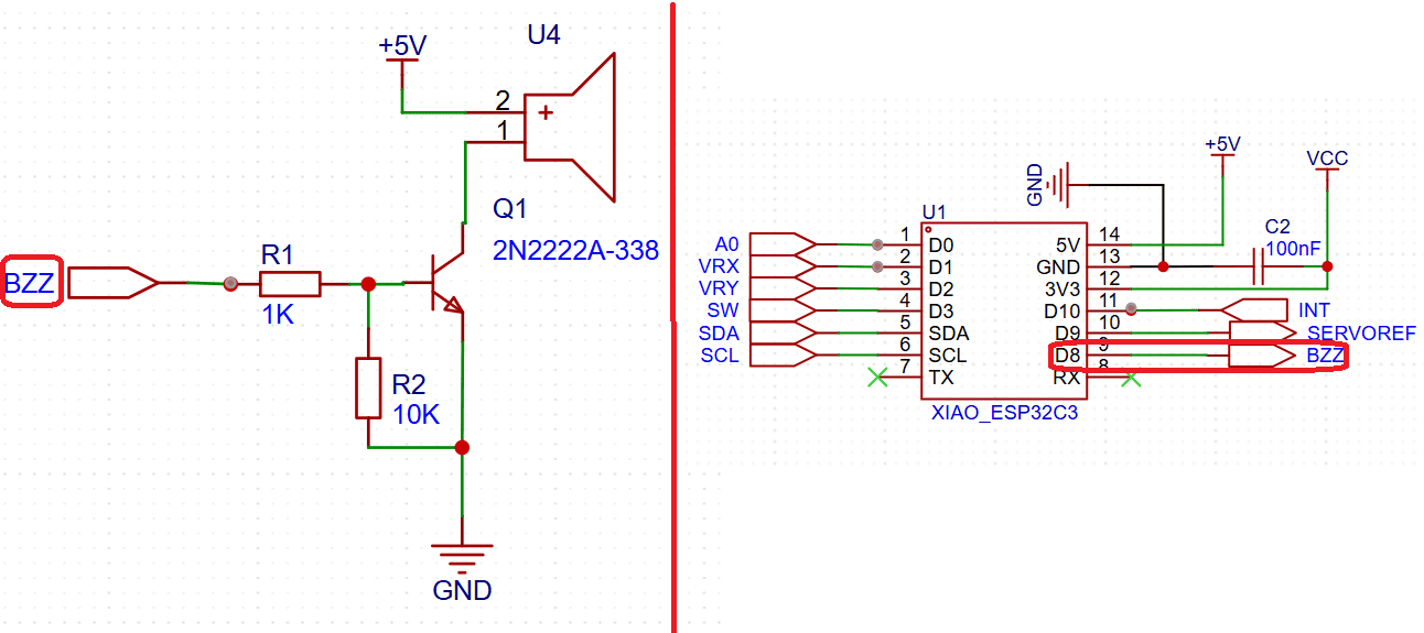
Buzzer control using NPN transistor as switching stage.
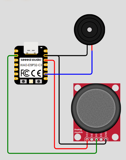
Wokwi simulation of PWM tone generation.
Program Code
#define buzzer D8
#define potX   D2

int notes[] = {262, 294, 330, 349, 392, 440, 494, 523};
int numNotes = 8;

void setup() {
  ledcAttach(buzzer, 2000, 10); // PWM channel for sound
}

void loop() {
  int value = analogRead(potX);

  int index = map(value, 0, 4095, 0, numNotes - 1);

  int freq = notes[index];

  ledcWriteTone(buzzer, freq);

  delay(50);
}
Code Explanation
-
PWM-Based Audio Generation:
The buzzer is driven using the ESP32-C3 LEDC module. Instead of controlling duty cycle,
the function
ledcWriteTone()generates a square wave with a specified frequency. This transforms the PWM hardware into a frequency generator, where each cycle corresponds to a vibration of the buzzer diaphragm. -
Understanding ledcWriteTone():
The function
ledcWriteTone(pin, frequency)dynamically configures the PWM signal to oscillate at the desired frequency. Internally, it adjusts the timer parameters of the LEDC peripheral to produce a square wave. Unlike standard PWM:- PWM (servo): fixed frequency, variable duty cycle
- Audio (buzzer): variable frequency, ~50% duty cycle
- Frequency Mapping to Musical Notes: A predefined array of frequencies represents musical notes (C4 to C5). The joystick input is mapped to an index within this array, effectively selecting a note based on position. This demonstrates a discrete mapping from analog input to quantized output.
-
Analog-to-Discrete Conversion:
The function
map()converts the continuous ADC range (0–4095) into discrete steps (0–7). This creates a digital selection mechanism where each interval corresponds to a specific musical note. - Real-Time Frequency Update: The loop continuously updates the frequency based on joystick position. This allows dynamic sound generation, where moving the joystick results in immediate changes in pitch.
- Signal Amplification via Transistor: The PWM signal from the microcontroller is used to switch the transistor ON and OFF. This effectively modulates the current flowing through the buzzer, enabling it to operate at higher power levels than the MCU alone could provide.
-
System Behavior:
The system can be understood as:
- Input: joystick position
- Processing: frequency selection
- Output: audible tone generation
System Validation – Simulation vs Physical
Wokwi Simulation
Open Tone Generation SimulationSimulation of tone generation in Wokwi.
Physical implementation with amplified buzzer output.
Final Reflection
This week focused on understanding how a microcontroller can generate and control different types of output signals to interact with the physical world. Through a series of experiments, I explored three distinct forms of output: mechanical motion (servo motor), visual feedback (OLED display), and sound generation (buzzer).
In the first experiment, I learned how PWM signals can be used to control the angular position of a servo motor. A key insight was understanding that PWM does not always represent power control, but can also encode positional information through pulse width. Additionally, I realized the importance of external power supply when working with actuators, as the current requirements exceed the capabilities of the microcontroller.
The second experiment introduced graphical output using an OLED display. This shifted the focus from physical actuation to data visualization. By working with pixel-based rendering and coordinate systems, I understood how graphical interfaces are built from basic geometric primitives. Implementing a galvanometer-style display also required applying trigonometry, which connected mathematical concepts with embedded systems.
In the third experiment, I explored sound generation using a passive buzzer. This highlighted a different use of PWM, where frequency rather than duty cycle becomes the key parameter. The use of a transistor as a switching stage reinforced the importance of designing proper driver circuits when dealing with output devices that require higher current or voltage levels.
One of the most important takeaways from this week is how the same microcontroller peripheral (PWM) can be used in fundamentally different ways: controlling position, generating sound, and driving external components. This demonstrates the versatility of embedded systems and the importance of understanding the underlying hardware.
Another key learning outcome was the integration of multiple output devices into a single system. By using a joystick as a common input, I was able to control mechanical motion, visualize the system state, and generate sound simultaneously. This reinforced the concept of modular system design and real-time interaction between different subsystems.
Finally, this week emphasized the importance of combining hardware and software knowledge. Successful implementation required not only writing correct code, but also understanding electrical constraints, communication protocols, and signal behavior. Debugging involved both software validation (using simulation tools like Wokwi) and hardware verification, highlighting the iterative nature of embedded system development.
Individual Reflection
This group assignment helped me better understand the electrical behavior of output devices beyond simply making them operate. While previous assignments focused on controlling actuators through software, this experiment emphasized the importance of evaluating their electrical requirements and understanding how much power they consume under different operating conditions.
One of the most valuable lessons was recognizing that voltage, current, and power are closely related but describe different aspects of a system's performance. Measuring these parameters with laboratory instruments allowed me to connect the theoretical power equation (P = V × I) with real experimental data and better understand how electrical energy is converted into mechanical motion by a DC motor.
I also learned that interpreting measurements requires understanding the operating conditions of the device. During the experiment, the motor was tested without mechanical load, which explained why the current remained nearly constant while the rotational speed increased as the supply voltage was raised. This demonstrated that power consumption depends not only on the applied voltage but also on the mechanical demand placed on the motor.
This experience reinforced the importance of considering power consumption during the design stage of embedded systems. As I continue developing custom electronic projects throughout Fab Academy, understanding the electrical requirements of actuators will help me select appropriate power supplies, estimate energy consumption, and design more reliable and efficient systems for my Final Project.
Downloads & Resources
This section provides access to the simulations and downloadable resources created during the Output Devices assignment. The experiments demonstrate different techniques for controlling actuators, graphical displays, and audio output devices using the XIAO ESP32-C3.
🔗 References & Simulations
The following Wokwi simulations reproduce each experiment developed during this assignment, allowing the programs to be tested and validated before running them on the physical hardware.
📁 Downloadable Files
To improve the loading performance of this documentation website, all project files have been moved to a shared Google Drive folder.
The repository contains the complete Arduino source code, project configurations, supporting libraries, and additional documentation developed during the Output Devices assignment.
The examples demonstrate PWM motor control, graphical OLED visualization, and audio signal generation using programmable output devices.