Assignment Requirements
- Model a possible final project using different CAD approaches (raster, vector, 2D, 3D, rendering, animation, or simulation).
- Compress images and videos used for documentation.
- Publish a clear description of the design process together with the original design files on your class page.
Learning Outcomes
- Evaluate and select appropriate 2D and 3D design software.
- Demonstrate and describe modelling processes using 2D and 3D tools.
- Demonstrate image and video compression techniques.
Progress Status
Summary of completed tasks for Week 02.
Comparison between free software Tinkercad and professional software SolidWorks for 3D modeling.
2D sketches created in SolidWorks, using fully constrained sketches with proper dimensions.
Rendering performed using a SolidWorks assembly, applying different materials and textures to individual parts.
Animated exploded view and motion simulation of an automatic door using SolidWorks.
Software Comparison: Tinkercad vs SolidWorks
For the development of this project, I decided to compare Tinkercad and SolidWorks in order to identify their main differences and evaluate their suitability for digital fabrication workflows.
Due to my professional experience, I have extensive knowledge of SolidWorks for parametric mechanical design based on fully constrained 2D sketches. However, I have limited experience with constructive design software based on predefined geometric primitives, which motivated me to explore Tinkercad.
Tinkercad - Constructive Modeling
Tinkercad was used to explore constructive modeling through direct manipulation of geometric primitives, boolean operations, and alignment tools.
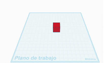
Step 1 -” Base geometry
Rectangular solid used as the starting point with defined dimensions.
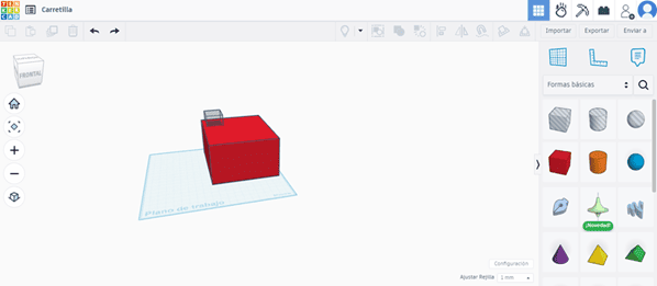
Step 2 -” Boolean cuts
Cutting primitives used to generate internal features.
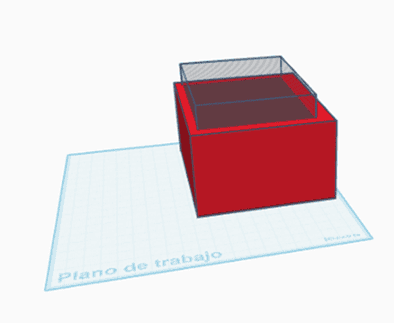
Step 3 -” Alignment
Alignment tools used to center geometry and control depth.
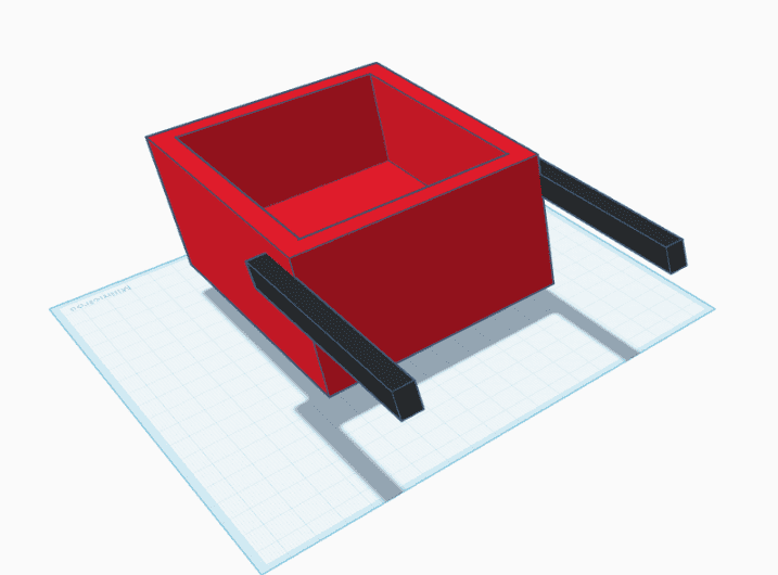
Step 4 - Components
Predefined wheels and custom load handles added to the model.
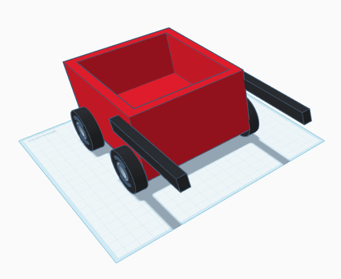
Step 5 - Final model
Completed constructive model ready for export.
Image files: tinkercad_01.png - tinkercad_05.png
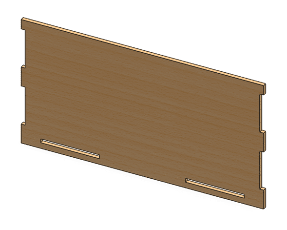
SolidWorks - Parametric Modeling
SolidWorks was used to develop a fully parametric, fabrication-oriented design based on constrained sketches and multi-part assemblies.
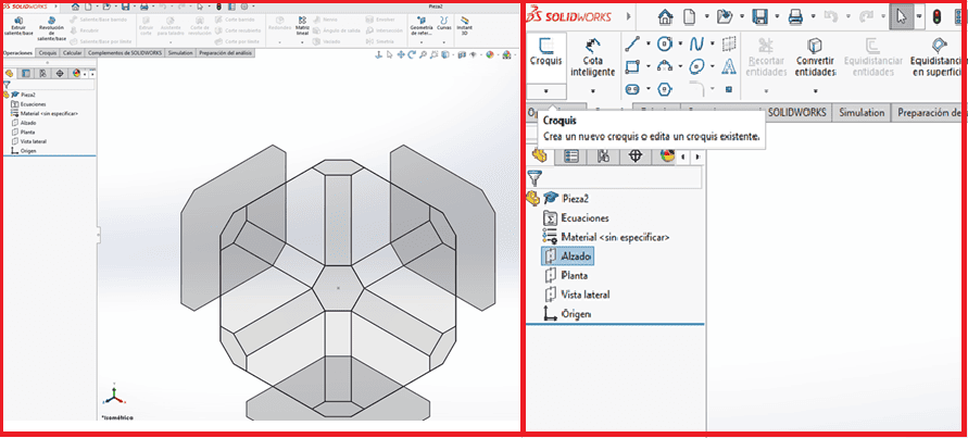
Step 1 - Plane selection
Selection of the reference plane to start the modeling process.
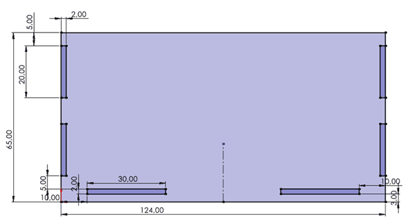
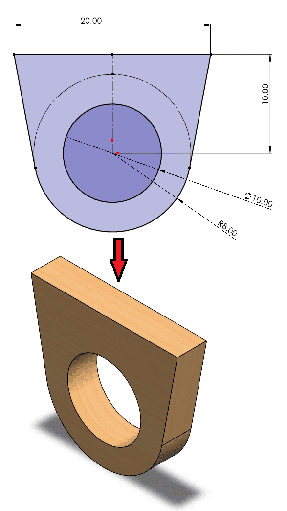
Step 2 - 2D sketch
Creation of a fully constrained 2D sketch using Smart Dimension.
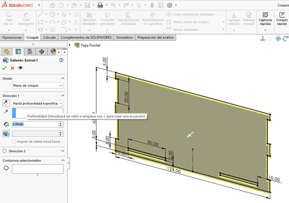
Step 3 - Extrude operation
Extrusion of the sketch to generate the initial 3D geometry.
Step 4 - Add material
Materials and textures applied to individual parts.
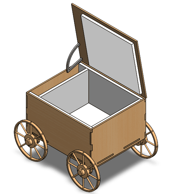
Step 5 - Assembly
Assembly of individual parts using positional relationships.
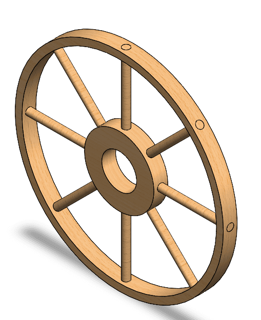
Step 6 - Wheel subassembly
Creation of a wheel subassembly to simplify assembly management.
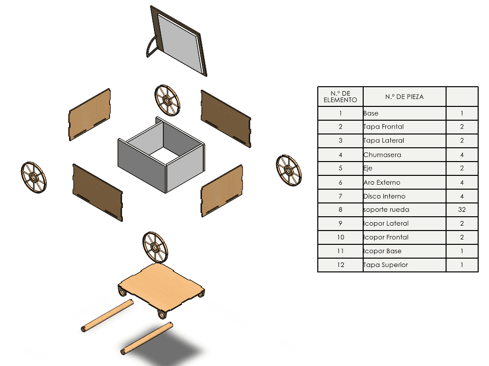
Step 7 - Exploded view and BOM
Exploded view with bill of materials for assembly and documentation.
Image files: solidworks_01.png - solidworks_07.png
2D Modeling with SolidWorks
2D modeling in SolidWorks is the foundation of any parametric 3D design. Even though SolidWorks is a 3D CAD software, all geometry starts from a 2D sketch defined on a selected reference plane.
Plane Selection
The first step is selecting a reference plane (Front, Top, or Right). This decision is critical because it defines the orientation of the sketch and how the part will be positioned in 3D space. A correct plane selection simplifies later operations such as extrusion, assembly, and manufacturing.
Origin and Reference
The sketch origin acts as the main reference point of the design. Positioning key geometry relative to the origin ensures better control, symmetry, and alignment. Proper use of the origin is essential for creating robust and predictable parametric models.
Dimensions (Cotas)
Dimensions define the size and scale of the geometry. By assigning precise values to lengths, diameters, and angles, the sketch becomes fully defined. These dimensions are parametric, meaning they can be modified later to update the entire model automatically.
Geometric Relations
Relations define how sketch entities interact with each other. Common relations include horizontal, vertical, parallel, perpendicular, coincident, and symmetric. These constraints ensure that the design behaves correctly when modified and maintains its intended shape.
A well-constructed sketch is fully constrained, meaning all geometry is defined by dimensions and relations. This guarantees stability, avoids unintended movement, and provides a solid base for generating 3D features such as extrusions or revolutions.
2D Vector Design with Inkscape
In addition to parametric 2D sketches in SolidWorks, I also explored vector-based graphic design using Inkscape. Inkscape is an open-source vector graphics editor commonly used for digital fabrication workflows such as laser cutting, vinyl cutting, logo creation, and SVG file preparation.
Unlike raster graphics, vector graphics are based on mathematical curves and geometric entities. This allows designs to be scaled without losing quality and makes them especially useful for fabrication processes that require precision.
Logo Development Process
For this exercise, I designed a custom “Fab Academy 2026 - 2D Design†logo inspired by vintage badge compositions. The objective was to experiment with geometric construction, symmetry, typography, and vector composition techniques.
The design process included the use of circular geometry, path-based text alignment, layered vector objects, color adjustments, and composition balancing. Different vector tools such as shape operations, alignment tools, node editing, and stroke control were used to refine the final result.
To document the workflow, the entire design process was recorded in real time while the logo was being created. This recording provides evidence of the vector design workflow and the different tools used throughout the development process.

Vector Design Workflow Video
The following video shows the complete workflow used to create the vector logo in Inkscape, including geometric construction, text positioning, shape editing, and final composition adjustments.
Rendering and Assembly in SolidWorks
Assembly modeling in SolidWorks allows the integration of multiple components into a single functional system using defined positional and geometric relationships. This approach makes it possible to verify fit, alignment, and mechanical coherence before manufacturing.
For this project, individual parts were assembled and organized into subassemblies to simplify design management and future modifications. The wheel was modeled as a dedicated subassembly, improving clarity and reusability within the main assembly.
Rendering was performed directly in SolidWorks by applying different materials and textures to each component. This process enhances visual understanding of the design and helps communicate material selection, surface finish, and overall structure.
As shown in the exploded view, the final assembly includes a clear representation of how all parts interact, along with a bill of materials (BOM) that supports documentation, fabrication planning, and assembly sequencing.
Animation and Motion Study in SolidWorks
SolidWorks animation tools were used to visually communicate the mechanical behavior, assembly logic, and movement of the project. The animation workflow was developed using the Motion Study environment, which allows the creation of dynamic simulations directly inside an assembly.
Motion Study combines animation tools, timeline-based control, motors, camera movement, and keyframe configuration to simulate mechanical motion. This environment is especially useful for validating assemblies, presenting design concepts, and generating technical visualization videos for documentation purposes.
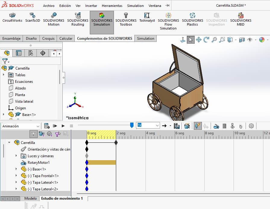
Motion Study Timeline
The first step in the animation process was creating a Motion Study inside the SolidWorks assembly. The timeline interface controls the duration of the animation, keyframes, component movement, and synchronization of all motion events.
The timeline works similarly to a video editor, where each component, camera movement, or motor action can be configured over time. This makes it possible to precisely control the sequence and behavior of the assembly during the simulation.
By adjusting the timeline length and playback intervals, the animation speed and motion smoothness can be optimized before exporting the final video.

Motor Tool and Oscillatory Motion
To simulate the movement of the mechanism, the Motor tool was added inside the Motion Study. Motors in SolidWorks allow controlled rotational or linear movement to be applied to selected components or assembly mates.
In this project, an oscillatory motion configuration was selected in order to create a repetitive back-and-forth movement. This type of motion is useful for demonstrating mechanical behavior without requiring a continuous rotational cycle.
Parameters such as speed, direction, frequency, and angular limits were adjusted to achieve a smoother and more realistic animation. This configuration allowed the mechanism to move in a controlled and visually understandable way during the simulation.
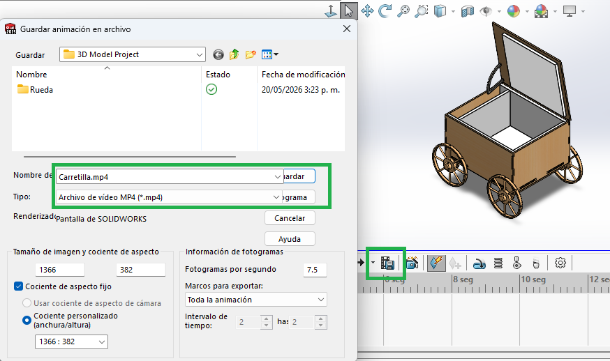
Frame Rate and Video Export
After validating the motion behavior, the animation was exported as a video file directly from SolidWorks. Export settings included resolution configuration, frame rate selection, and rendering quality adjustments.
The animation was configured using a specific frames-per-second (FPS) value in order to achieve smoother motion playback and improve visual quality. Higher FPS values generate more fluid animations but also increase rendering time and file size.
Finally, the animation was exported in AVI format, which is one of the standard video formats supported by SolidWorks for Motion Study rendering. The exported file was later compressed for web documentation and embedded into this assignment page.
Functional Animation
This animation shows the fully assembled model in motion, allowing evaluation of proportions, mechanical behavior, and component interaction. Animated visualization helps validate the concept before fabrication and improves understanding of the assembly operation.


Exploded View Animation
The exploded animation illustrates the assembly sequence and spatial relationship between all components of the project. This type of visualization separates each part in a controlled way, making it easier to understand how the assembly is organized and how individual components interact with one another.
In SolidWorks, the exploded view was created by defining sequential displacement steps for each component inside the assembly. Different directions and distances were assigned to the parts in order to maintain visual clarity and avoid overlap during the animation process.
After defining the exploded configuration, the movement sequence was animated through the Motion Study timeline. This allowed the assembly process to be represented dynamically, showing how the product can be assembled or disassembled step by step.
Exploded animations are especially useful for technical documentation, fabrication planning, maintenance references, and presentation purposes because they provide a clearer understanding of component hierarchy, assembly order, and mechanical relationships within the final product.
Image Compression Workflow
Image optimization is essential for efficient web documentation, as it reduces loading times and improves performance. In this assignment, two tools were evaluated: iLoveIMG and Squoosh, comparing compression efficiency, usability, and level of control.
iLoveIMG - Batch Compression Workflow
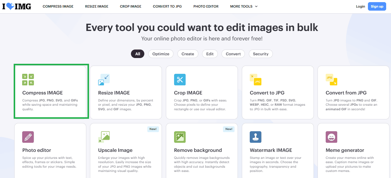
Step 1 - Image Selection: Multiple images were selected from the local directory in order to process them simultaneously. This demonstrates the batch-processing capability of iLoveIMG.
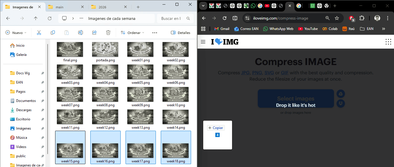
Step 2 - Upload Process: The selected images were uploaded into the platform. The interface allows fast handling of large image sets without requiring manual configuration.
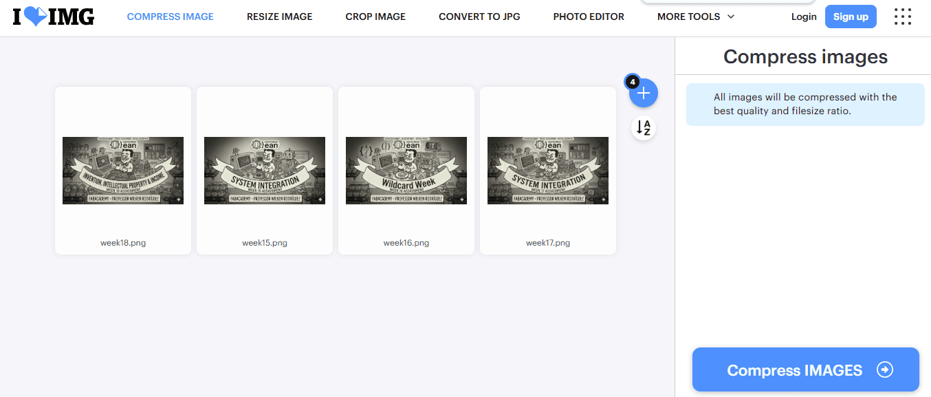
Step 3 - Automatic Compression: iLoveIMG applies automatic lossy compression to all images simultaneously, optimizing file size while preserving acceptable visual quality.
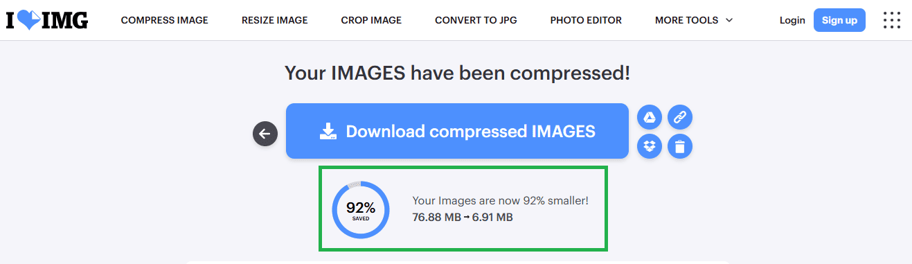
Step 4 - Results: The final output shows a total reduction of 92% in file size, decreasing from 76.88 MB to 6.91 MB. This demonstrates the efficiency of batch compression for large datasets.
Squoosh - Advanced Compression Control
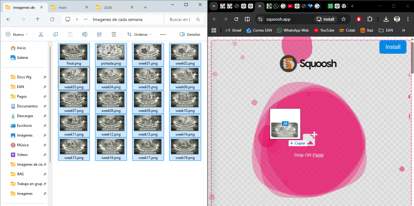
Step 1 - Image Import: A single image is uploaded into Squoosh. Unlike batch tools, Squoosh focuses on detailed, per-image optimization.
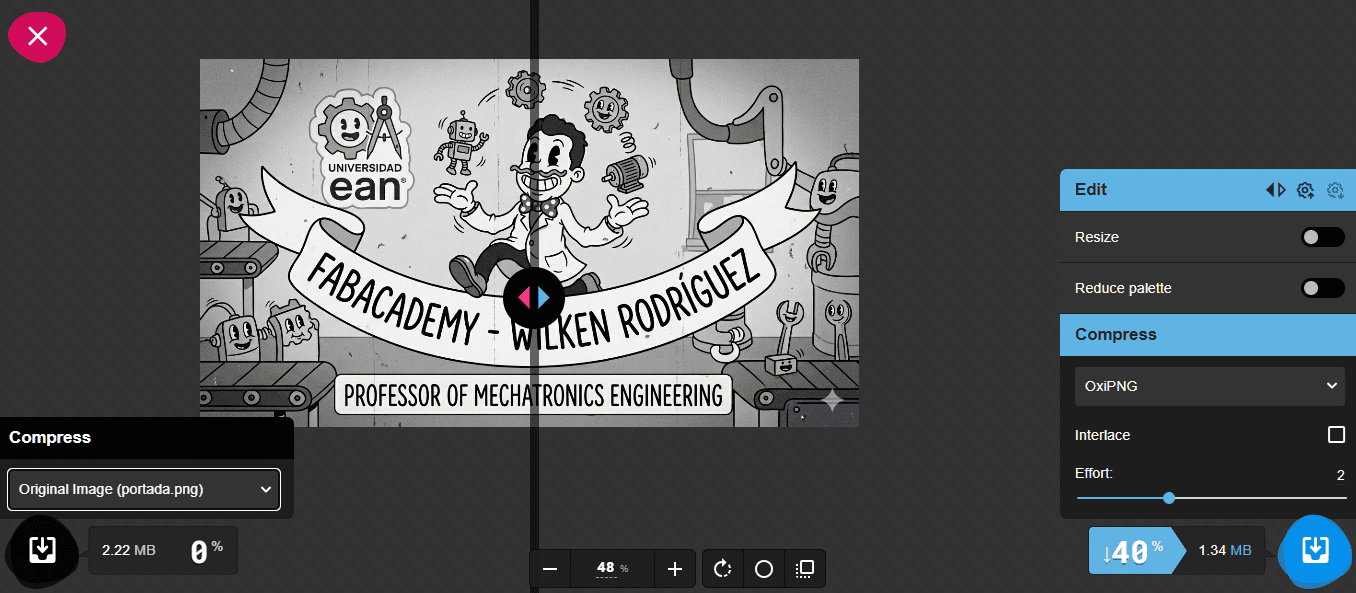
Step 2 - Parameter Adjustment: Squoosh allows real-time comparison between the original and compressed image, enabling precise adjustments of quality, resolution, and compression format such as WebP or MozJPEG.
Tool Comparison
| Tool | Compression Type | Strengths | Limitations |
|---|---|---|---|
| iLoveIMG | Automatic (Lossy) | Fast, batch processing, high reduction rate | Limited parameter control |
| Squoosh | Manual (Lossy / Lossless) | Precise control, real-time preview, multiple formats | Single image processing |
Conclusion
The comparison shows that Squoosh provides more advanced compression capabilities and better control over image quality, making it ideal for fine-tuning individual images. However, iLoveIMG offers a more practical solution for documentation workflows, as it enables efficient batch processing of large image sets while still achieving significant file size reduction.
For this project, iLoveIMG was selected as the primary tool due to its speed, ease of use, and ability to handle multiple images simultaneously.
Video Compression Workflow
Video optimization is essential for reducing file size and improving loading performance in web documentation. In this assignment, two online tools were evaluated: Clideo and VEED.IO, comparing ease of use, compression efficiency, and additional features.
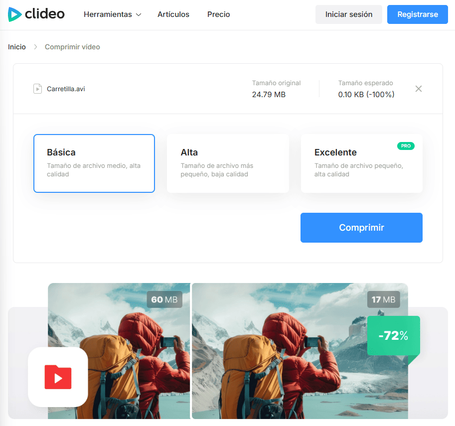
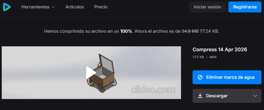
Clideo - Automatic Compression

Step 1 - Access Tool: The Clideo video compressor interface allows quick access to video optimization directly from the browser.
Step 2 - Upload Video: The video file is uploaded into the platform. Clideo supports automatic processing without requiring advanced configuration.
Step 3 - Compression Selection: The platform offers predefined compression levels such as basic, high, and excellent, simplifying the workflow for quick optimization.

Step 4 - Result: The compressed video shows a significant reduction in file size while maintaining acceptable visual quality. However, the process is mostly automatic and offers limited control over parameters.
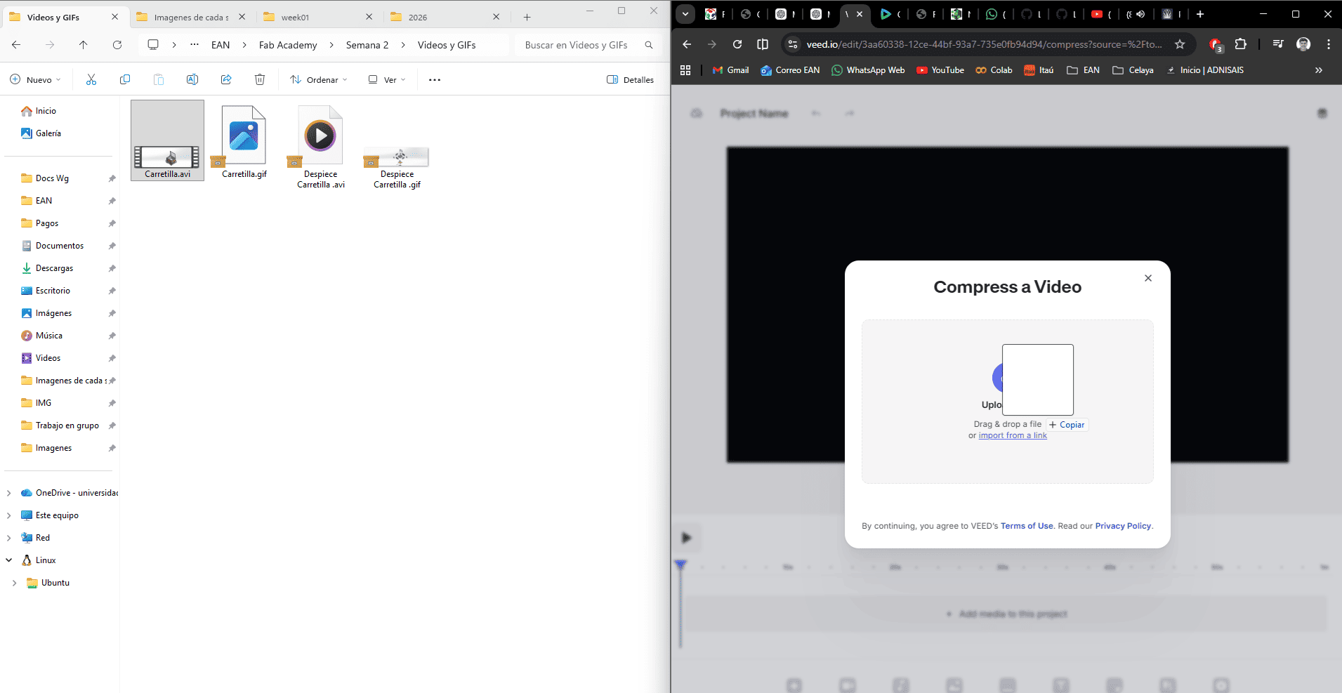
VEED.IO - Advanced Compression and Editing
Step 1 - Platform Interface: VEED provides a more advanced interface, combining video compression with editing tools such as trimming, timeline control, and preview.
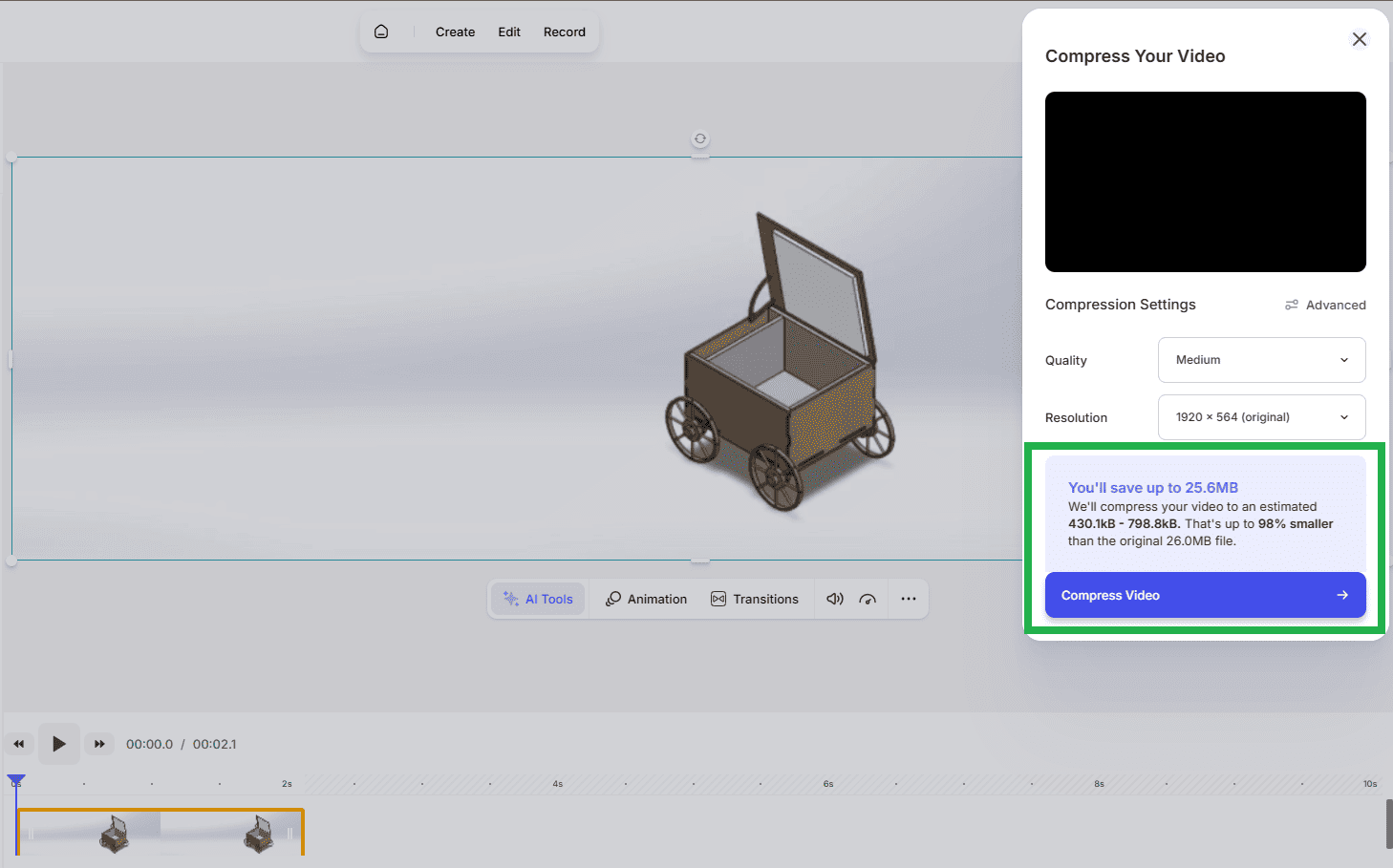
Step 2 - Compression Settings: VEED allows adjustment of quality, resolution, and compression level. It also provides an estimation of file size reduction, offering better control compared to automatic tools.
Tool Comparison
| Tool | Type | Strengths | Limitations |
|---|---|---|---|
| Clideo | Automatic | Fast, simple workflow, easy to use | Limited control over compression |
| VEED.IO | Manual / Semi-manual | Adjustable quality, resolution, editing tools | Slightly slower workflow |
Conclusion
The comparison shows that Clideo provides a fast and efficient solution for automatic video compression, making it suitable for quick optimization tasks. However, VEED.IO offers greater flexibility by allowing control over compression parameters and including basic video editing tools.
For this project, VEED.IO was considered the most complete solution, as it not only compresses videos efficiently but also enables basic editing and fine-tuning, making it more suitable for structured documentation workflows in Fab Academy.
Final Reflections
This week provided a comprehensive introduction to digital design workflows, covering both 2D and 3D modeling, as well as image optimization for documentation. One of the most important takeaways was understanding that different tools are suited for different stages of the design and fabrication process.
From a 3D perspective, SolidWorks proved to be a powerful parametric design tool, allowing precise control over geometry through fully constrained sketches. This approach ensures that the design is robust, modifiable, and suitable for real-world fabrication. In contrast, Tinkercad offered a more intuitive and visual workflow based on constructive geometry, making it ideal for rapid prototyping and conceptual exploration.
In terms of 2D design, this week highlighted the importance of sketches as the foundation of any parametric model. A well-defined sketch, supported by proper dimensions and geometric relations, directly impacts the quality and stability of the final 3D model. This reinforces the idea that strong fundamentals in 2D design are essential for successful digital fabrication workflows.
The image compression exercise also introduced an important aspect of documentation: optimization. While tools like Squoosh provide advanced control over compression parameters and output quality, iLoveIMG demonstrated a more efficient workflow for handling large batches of images. This comparison emphasized the need to balance quality, control, and efficiency depending on the context.
Overall, this week reinforced the idea that digital fabrication is not only about designing objects, but also about selecting the right tools, understanding their limitations, and building efficient workflows from design to documentation. These skills will be essential for the development of the final project.
Downloads & References
This section contains the external resources and downloadable files related to the Computer-Aided Design assignment. The project combines parametric modeling in SolidWorks with constructive solid geometry developed in Tinkercad.
🔗 References & Online Models
The following links provide access to the online CAD resources used during this assignment. They include the interactive Tinkercad model developed as part of the constructive solid geometry exercise.
📁 Downloadable Files
To improve the loading performance of this documentation website, all project files have been moved to a shared Google Drive folder.
The folder contains the complete SolidWorks project, including parts, assemblies, parametric sketches, engineering drawings, exported models, and supporting documentation created during Week 02.
Additional project files and updated versions may be added as the documentation continues to evolve.