Individual Assignment
- Design, build and connect wired or wireless node(s) with network or bus addresses and a local input and/or output device(s).
Learning Outcomes
- Demonstrate workflows used in network design.
- Implement and interpret networking protocols and communication protocols.
Progress Status – Networking & Communications
Understanding, implementing and validating communication protocols on my custom XIAO ESP32-C3 development board.
Explored UART communication, COM ports, baud rate configuration, TX/RX transmission, and serial monitoring using the Arduino IDE Serial Monitor.
Implemented master-slave communication over the I²C bus using an SSD1306 OLED display with the address
0x3C.
Developed and tested a complete embedded system combining UART debugging, I²C communication, joystick input, OLED visualization, and servo control.
System Overview – Embedded Communication Architecture
This week's assignment focuses on how embedded systems exchange information using communication protocols instead of dedicated control signals. Rather than connecting every peripheral with independent wires, modern microcontrollers communicate through standardized interfaces such as UART and I²C, allowing multiple devices to share data efficiently.
For this project, I reused the custom PCB developed in Week 08 based on the XIAO ESP32-C3. The same hardware platform was extended to demonstrate two of the most common communication protocols in embedded systems: UART for serial communication with the computer and I²C for communication with an SSD1306 OLED display.
System Architecture
The embedded system consists of four main elements:
- Input: Analog joystick used to control the servo position.
- Processing: XIAO ESP32-C3 executing the application logic.
- I²C Output: SSD1306 OLED display (slave device, address
0x3C) for graphical feedback. - UART Output: Serial communication with the computer through the USB COM port for monitoring and debugging.
During execution, the microcontroller continuously reads the joystick position, updates the servo angle, sends graphical information to the OLED display through the I²C bus, and transmits debugging messages over the UART interface. This demonstrates how multiple communication channels can operate simultaneously within the same embedded system.
The following sections explain the fundamentals of UART and I²C communication before presenting the complete implementation, simulation, and hardware validation.
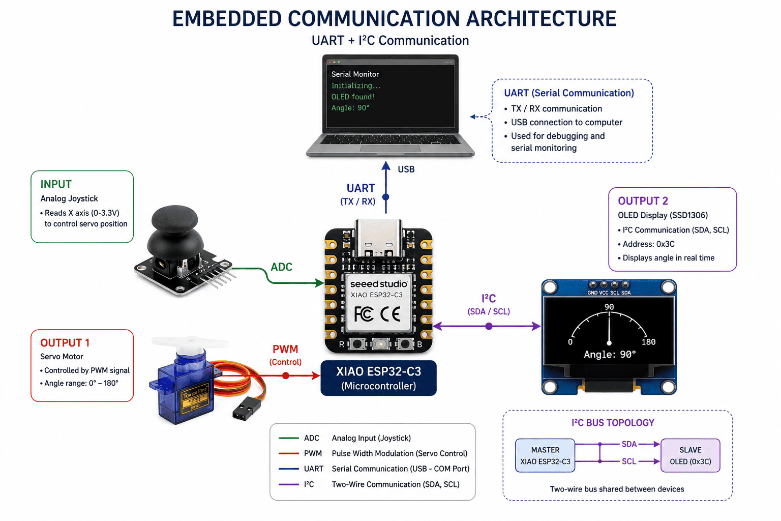
Communication architecture showing the XIAO ESP32-C3 exchanging data through UART and I²C communication protocols.
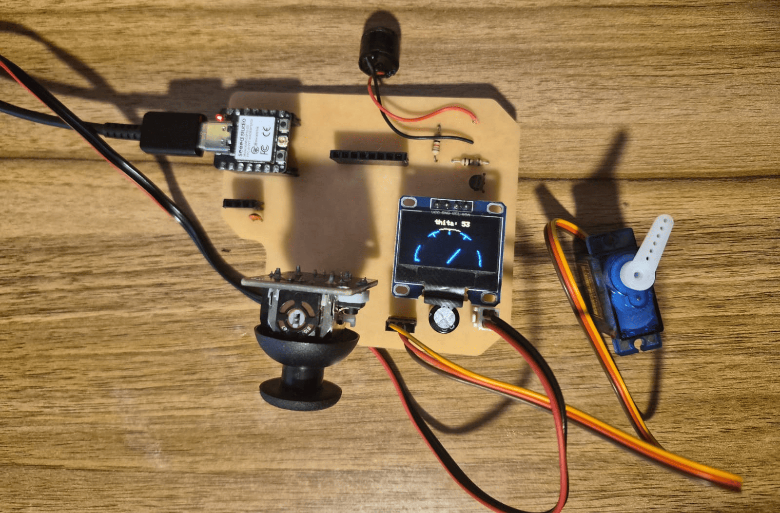
Physical implementation using the custom XIAO ESP32-C3 PCB, joystick, servo motor, and SSD1306 OLED display.
Serial Communication – UART & COM Port
What is Serial Communication?
Serial communication is a method of transmitting digital information one bit at a time between electronic devices through a communication channel. Unlike parallel communication, which requires multiple data lines, serial communication uses fewer wires while maintaining reliable and efficient data transfer.
Because of its simplicity and low hardware requirements, serial communication is one of the most widely used techniques in embedded systems for exchanging information between microcontrollers, computers, sensors, and peripheral devices.
UART Communication Protocol
UART (Universal Asynchronous Receiver Transmitter) is one of the most common serial communication protocols used in embedded systems. It is called asynchronous because the transmitter and receiver do not share a clock signal. Instead, both devices must be configured with the same communication parameters such as baud rate, data bits, parity, and stop bits.
Communication occurs through two dedicated signals:
- TX (Transmit): sends data.
- RX (Receive): receives data.
During transmission, UART sends each byte as a sequence consisting of a start bit, data bits, an optional parity bit, and one or more stop bits, allowing the receiver to reconstruct the original information.
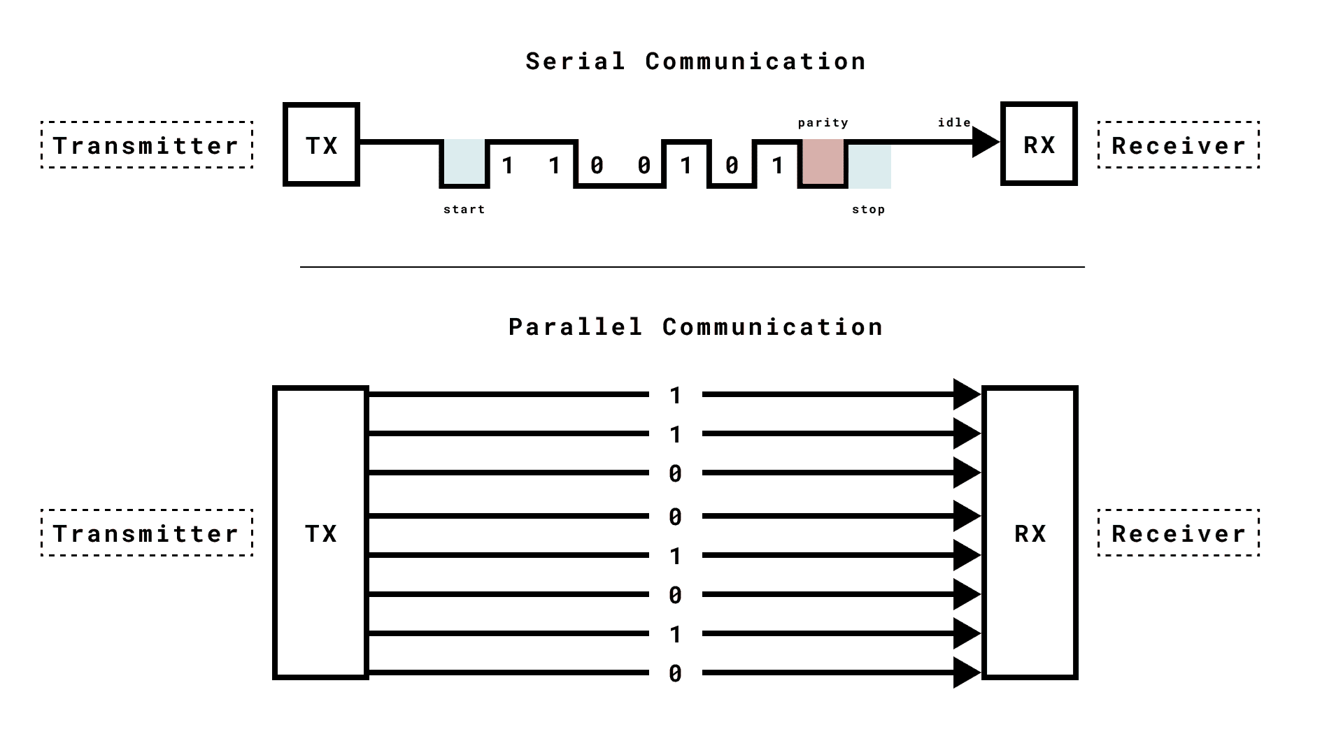
UART communication uses independent TX and RX lines to exchange data between devices
without requiring a shared clock signal.
Adapted from the
Arduino UART Documentation
.
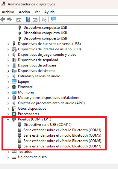
USB connection creates a virtual COM Port that allows the Arduino IDE to communicate with the microcontroller.
What is a COM Port?
A COM Port (Communication Port) is the virtual serial interface created by the operating system when a USB-enabled microcontroller is connected to a computer. Although modern computers no longer include traditional RS-232 serial connectors, USB communication emulates a serial port that software can access.
When the XIAO ESP32-C3 is connected through USB, the operating system assigns a COM Port
(such as COM5 on Windows or /dev/ttyUSB0 on Linux), allowing development
environments like the Arduino IDE to upload programs and exchange serial data.
This communication channel is also used by the Serial Monitor, where debugging messages
generated by functions such as Serial.print() and
Serial.println() can be observed in real time.
UART Communication in this Project
During the development of this assignment, UART communication was used to establish a serial connection between the XIAO ESP32-C3 and the computer. The communication channel was initialized in the Arduino IDE using:
Serial.begin(115200);
The selected baud rate of 115200 bps defines the communication speed between both devices. Once initialized, the Serial Monitor receives debugging messages that verify the correct initialization of the OLED display and assist in monitoring the behavior of the embedded application during execution.
I²C Communication – Bus Addressing
What is I²C Communication?
I²C, which stands for Inter-Integrated Circuit, is a synchronous serial communication protocol commonly used to connect microcontrollers with sensors, displays, memory devices, and other peripherals.
Unlike UART, which uses independent TX and RX lines, I²C uses a shared two-wire bus. This means that multiple devices can be connected to the same communication lines, reducing wiring complexity and allowing the microcontroller to communicate with several peripherals through the same interface.
I²C Bus Lines
The I²C bus uses two main signals:
- SDA (Serial Data): carries the data between devices.
- SCL (Serial Clock): carries the clock signal generated by the master device.
Because I²C is synchronous, the clock line coordinates when data is transmitted and read. This makes the communication more structured and allows several devices to share the same bus.
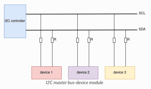
I²C communication uses two shared lines, SDA and SCL, allowing multiple addressed
devices to communicate on the same bus.
Adapted from the
Inter-Integrated Circuit (I²C) ESPRESSIF Article
.
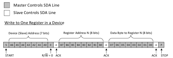
Example of an I²C write transaction showing the START condition,
7-bit slave address, register address, data byte, ACK bits, and
STOP condition.
Adapted from
Texas Instruments – Understanding the I²C Bus
.
Master, Slave and Bus Address
I²C communication is based on a master-slave structure. The master device controls the clock signal and starts the communication, while the slave devices wait until they are addressed.
In this assignment, the XIAO ESP32-C3 works as the master, and the SSD1306 OLED display works as the slave. The OLED display is accessed through its I²C address:
0x3C
This address is important because it allows the microcontroller to identify the OLED display on the bus. If multiple I²C devices were connected, each one would need a different address so the master could communicate with them individually.
I²C Communication in this Project
In this project, I²C communication was used to send graphical information from the XIAO ESP32-C3 to the SSD1306 OLED display. The bus was initialized in the Arduino IDE using the Wire library:
#include <Wire.h>

Wire.begin();

display.begin(SSD1306_SWITCHCAPVCC, 0x3C);
The Wire.begin() function starts the I²C bus, while
display.begin(SSD1306_SWITCHCAPVCC, 0x3C) initializes the OLED display
using its bus address. After initialization, the microcontroller can send commands
and pixel data to update the display.
The OLED display is used as a local output device to show the angular position of the servo motor in real time. This demonstrates the use of an addressed communication bus with a local output device, which directly supports the objective of the Networking and Communications assignment.
Experiment – UART and I²C Communication System
Experiment Intention
The intention of this experiment was to build an embedded system that demonstrates communication between a microcontroller, a computer, and an addressed peripheral device. The system uses the XIAO ESP32-C3 as the main controller, an analog joystick as the local input device, a servo motor as a physical output, and an SSD1306 OLED display as a graphical output connected through the I²C bus.
In this setup, UART communication is used between the XIAO ESP32-C3 and the computer
through the USB COM Port for programming and serial monitoring. At the same time,
I²C communication is used to send graphical data from the microcontroller to the OLED
display, which works as an addressed slave device using the address 0x3C.
System Behavior
The joystick controls the angular position of the servo motor. The microcontroller reads the analog value from the joystick, maps it into an angle range, updates the servo position using a PWM signal, and sends the same angle information to the OLED display through I²C. This creates a synchronized system where the physical movement and the graphical visualization are updated in real time.
- UART: communication with the computer through the USB COM Port.
- I²C: communication with the OLED display using SDA and SCL.
- Analog input: joystick position read by the microcontroller.
- PWM output: servo motor angle control.
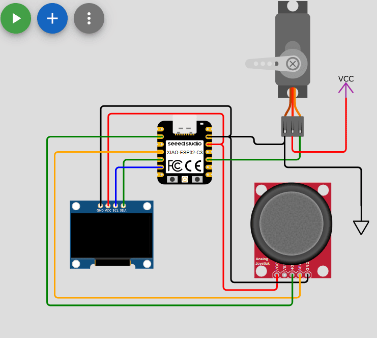
Circuit diagram of the communication system: joystick input, servo output, OLED display over I²C, and serial communication through USB.
Circuit Diagram Explanation
The diagram shows the XIAO ESP32-C3 connected to three main external components. The analog joystick is connected to power, ground, and an analog input pin. Its X-axis signal is used as the local input that controls the system behavior.
The servo motor is connected to an external power supply and controlled by a PWM signal from the microcontroller. A common ground connection is required between the servo power supply and the XIAO ESP32-C3 so that the control signal has a shared voltage reference.
The SSD1306 OLED display is connected using the I²C protocol. Its SDA and SCL pins are
connected to the corresponding I²C pins of the XIAO ESP32-C3, while VCC and GND provide
power. The display is accessed in the code using its I²C address 0x3C, which
allows the microcontroller to identify it on the bus.
This circuit satisfies the assignment requirement because it includes a local input device, local output devices, and an addressed communication bus. The OLED display acts as a node on the I²C bus, while UART communication through the USB COM Port is used for monitoring and debugging the system during development.
Arduino IDE Code
The code integrates UART communication, I²C communication, analog input reading, PWM servo control, and graphical rendering on the OLED display. Instead of showing the full code directly, the complete program is available below in a collapsible section.
#include <Adafruit_GFX.h>
#include <Adafruit_SSD1306.h>
#include <Wire.h>

// Pin definition
#define SDA   D4
#define SCL   D5
#define servo D9
#define potX  D2

// SSD1306 display characteristics
#define height 64
#define width 128
#define rst    -1

// Display object creation using the SSD1306 library
Adafruit_SSD1306 display(width, height, &Wire, rst);

// Process variables
int thita = 0;
int potValue = 0;
int midPoint = 2222;

void setup() {
  ledcAttach(servo, 50, 12);

  Serial.begin(115200);
  Wire.begin();

  if(!display.begin(SSD1306_SWITCHCAPVCC, 0X3C)){
    Serial.println("Oled Display NOT Found...");
    for(;;);
  }

  displayTxtConfig(2, 15, 0);
  display.clearDisplay();
  display.println("Servo Motor");

  displayTxtConfig(2, 40, 30);
  display.println("Control");
  display.display();

  Serial.println("Servo Motor Control");
  delay(3000);
}

void loop() {
  int value;
  value = analogRead(potX);

  if(value - midPoint > 100){ thita += 1; }
  if(value - midPoint < -100){ thita -= 1; }

  if(thita < 0){ thita = 0; }
  if(thita > 180){ thita = 180; }

  moveServo();
  displayAngle();
}

void displayTxtConfig(int size, int x, int y){
  display.setTextSize(size);
  display.setTextColor(WHITE);
  display.setCursor(x, y);
}

void displayAngle() {
  display.clearDisplay();

  int cx = 64;
  int cy = 63;
  int r = 50;

  for (int ang = 0; ang <= 180; ang += 2) {
    float rad = ang * PI / 180.0;
    int x = cx + r * cos(rad);
    int y = cy - r * sin(rad);
    display.drawPixel(x, y, WHITE);
  }

  for (int ang = 30; ang <= 180; ang += 30) {
    float rad = ang * PI / 180.0;

    int x1 = cx + (r - 5) * cos(rad);
    int y1 = cy - (r - 5) * sin(rad);

    int x2 = cx + r * cos(rad);
    int y2 = cy - r * sin(rad);

    display.drawLine(x1, y1, x2, y2, WHITE);
  }

  float rad = thita * PI / 180.0;

  int x = cx + (r - 10) * cos(rad);
  int y = cy - (r - 10) * sin(rad);

  display.drawLine(cx, cy, x, y, WHITE);

  display.setTextSize(1);
  display.setCursor(40, 0);
  display.print("thita: ");
  display.print(thita);
  display.display();

  Serial.print("Thita:");
  Serial.print(thita);
  Serial.print("°\n");
}

void moveServo(){
  int duty = map(thita, 0, 180, 102, 512);
  ledcWrite(servo, duty);
}
Important Code Sections
Libraries and I²C Object
#include <Adafruit_GFX.h>
#include <Adafruit_SSD1306.h>
#include <Wire.h>

Adafruit_SSD1306 display(width, height, &Wire, rst);
Wire.h enables I²C communication. Adafruit_GFX provides
drawing functions such as pixels, lines, text, and shapes. Adafruit_SSD1306
controls the OLED driver. The &Wire parameter is important because it
tells the display object to use the microcontroller's I²C bus managed by the
Wire library.
UART and I²C Initialization
Serial.begin(115200);
Wire.begin();

display.begin(SSD1306_SWITCHCAPVCC, 0x3C);
Serial.begin(115200) starts UART communication through the USB COM Port.
Wire.begin() starts the I²C bus. display.begin() initializes
the OLED display using its I²C address 0x3C, allowing the microcontroller
to identify it as a device on the bus.
Joystick Reading and Angle Update
int value = analogRead(potX);

if(value - midPoint > 100){ thita += 1; }
if(value - midPoint < -100){ thita -= 1; }

if(thita < 0){ thita = 0; }
if(thita > 180){ thita = 180; }
The joystick X-axis is read as an analog value. A threshold of 100
prevents small electrical variations from moving the servo unintentionally. The
angle variable thita is limited between 0° and
180°.
Servo PWM Control
ledcAttach(servo, 50, 12);

int duty = map(thita, 0, 180, 102, 512);
ledcWrite(servo, duty);
ledcAttach() configures the ESP32 PWM output for the servo motor.
The angle is mapped into a duty cycle range, and ledcWrite() updates
the PWM signal that controls the servo position.
OLED Drawing Methods
display.clearDisplay();
display.drawPixel(x, y, WHITE);
display.drawLine(x1, y1, x2, y2, WHITE);
display.setCursor(40, 0);
display.print(thita);
display.display();
The OLED uses a buffer-based drawing workflow. First, clearDisplay()
clears the display buffer. Then, drawing methods such as drawPixel(),
drawLine(), setCursor(), and print() prepare
the frame. Finally, display.display() sends the buffer to the OLED
through I²C.
Serial Monitoring
Serial.print("Thita:");
Serial.print(thita);
Serial.print("°\n");
These instructions send the current servo angle to the Arduino IDE Serial Monitor. This helped verify the system behavior through UART while the OLED display was being updated through the I²C bus.
Simulation Validation – Wokwi
Before assembling the hardware, the complete communication system was implemented and tested in Wokwi. The simulation reproduced the behavior of the XIAO ESP32-C3, the analog joystick, the servo motor, and the SSD1306 OLED display, allowing the communication protocols to be validated before building the physical setup.
The simulation confirmed that UART communication was correctly initialized for serial
monitoring, while the I²C bus successfully exchanged data with the OLED display using
its address 0x3C. It also verified the synchronization between the joystick
input, servo movement, and the graphical feedback displayed on the OLED.
Performing these tests in a virtual environment simplified debugging, reduced the possibility of wiring errors, and ensured that both communication protocols operated correctly before transferring the project to the custom PCB.
Wokwi simulation demonstrating UART monitoring, joystick input, servo movement, and real-time OLED updates through the I²C bus.
Physical Implementation & System Validation
After validating the communication protocols in Wokwi, the project was transferred to the physical hardware using the custom PCB developed in Week 08. The final implementation integrates the XIAO ESP32-C3, an analog joystick, a servo motor, and an SSD1306 OLED display, reproducing the same behavior previously verified in simulation.
During testing, the joystick controlled the servo position through PWM while the OLED display continuously received graphical updates through the I²C bus. At the same time, UART communication remained active, allowing debugging messages and angle values to be monitored from the Arduino IDE Serial Monitor via the USB COM Port.
Final hardware implementation using the custom XIAO ESP32-C3 PCB.
Real-time operation of the embedded communication system.
Communication Validation Checklist
UART Validation
- ✅ USB COM Port detected
- ✅ Serial communication initialized at 115200 baud
- ✅ Debug messages displayed correctly
- ✅ Servo angle monitored through Serial Monitor
I²C Validation
- ✅ I²C bus initialized successfully
- ✅ OLED detected at address 0x3C
- ✅ Graphical interface updated correctly
- ✅ Real-time synchronization with servo movement
The successful operation of both communication protocols demonstrates that the system satisfies the assignment requirements by integrating a local input device, multiple output devices, UART serial communication, and an addressed I²C communication bus within a single embedded application.
Final Reflection
This week changed the way I think about embedded systems. In previous assignments, my focus was mainly on controlling individual devices through digital signals, analog inputs, or PWM outputs. During the Networking and Communications week, I realized that modern embedded systems are built around communication protocols that allow multiple devices to exchange information efficiently instead of relying on dedicated connections for every component.
One of the most valuable concepts I learned was the difference between UART and I²C communication. Although both are serial protocols, they solve different problems. UART provides a simple point-to-point communication channel that is ideal for programming, debugging, and monitoring through the computer's COM Port. In contrast, I²C allows several devices to share the same communication bus, making hardware connections simpler while introducing concepts such as master-slave communication and device addressing.
Another important lesson was understanding that communication protocols are not only
software libraries. Behind functions such as Serial.begin() or
Wire.begin(), there is a complete hardware architecture involving timing,
synchronization, communication buses, and data transmission. Learning how these protocols
operate helped me better understand the relationship between software and electronics.
Developing the project also reinforced the importance of following an engineering workflow. Validating the communication in Wokwi before assembling the physical hardware made debugging much easier and reduced implementation errors. Once transferred to the custom PCB, the system behaved exactly as expected, confirming that both the UART and I²C communication channels had been correctly implemented.
Looking ahead to my Final Project, this assignment provides an important foundation. The project will require multiple modules to exchange information reliably, and the communication techniques explored this week will allow different devices to work together as a complete embedded system rather than as isolated components. Understanding communication protocols is therefore a fundamental step toward building scalable and modular electronic designs.
Individual Reflection
Participating in this group assignment allowed me to explore a different approach to embedded communication by working with ESP-NOW, a protocol that enables direct wireless communication between ESP32 devices. Unlike UART or I²C, which require physical connections, ESP-NOW demonstrated how multiple embedded systems can exchange information efficiently without additional network infrastructure.
One of the most interesting aspects of this activity was understanding the importance of the MAC address in peer-to-peer communication. Learning how each device identifies its communication partner and how peers are registered before data transmission helped me better understand the initialization process behind wireless embedded networks.
I also reinforced my understanding of event-driven programming through the receiver implementation. Using callback functions to process incoming packets showed me a more efficient programming model, where the microcontroller reacts only when new information is available instead of continuously polling for data.
This experience complemented my individual assignment by introducing a wireless communication protocol alongside the wired protocols I previously studied. Together, these activities gave me a broader understanding of embedded networking and helped me recognize that selecting the appropriate communication protocol depends on the application requirements, hardware architecture, and desired communication range.
Downloads & Resources
This section provides access to the simulations and downloadable resources created during the Output Devices assignment. The experiments demonstrate different techniques for controlling actuators, graphical displays, and audio output devices using the XIAO ESP32-C3.
🔗 References & Simulations
The following Wokwi simulations reproduce each experiment developed during this assignment, allowing the programs to be tested and validated before running them on the physical hardware.
📁 Downloadable Files
To improve the loading performance of this documentation website, all project files have been moved to a shared Google Drive folder.
The repository contains the complete Arduino source code, project configurations, supporting libraries, and additional documentation developed during the Output Devices assignment.
The examples demonstrate PWM motor control, graphical OLED visualization, and audio signal generation using programmable output devices.