Group Assignment Requirements
- Design a machine that includes mechanism, actuation, automation, and application.
- Build the mechanical parts and operate the machine manually (Part 1).
- Actuate and automate the machine (Part 2).
- Document the complete group project.
Project Overview – ReFil
The project developed for this assignment is ReFil – Filament Rewinding Machine, a system designed to rewind 3D printing filament from one spool to another in a controlled and efficient way.
The machine integrates:
- Mechanism: spool holders, filament guide system, and transmission system
- Actuation: electric motor to drive the filament
- Automation: custom PCB and embedded control
- Application: filament organization and reuse for 3D printing
Learning Outcomes
- Work and communicate effectively as a team
- Design, plan, and build a functional machine
- Integrate mechanical, electronic, and software systems
- Analyze and solve technical problems
- Identify opportunities for design improvement
Project Status – ReFil Development
Final development status of the filament rewinding machine.
🎬 ReFill – Final Demonstration
This video presents the final operation of the ReFill machine, demonstrating the filament rewinding process, system automation, and overall performance.
Final system demonstration showing controlled filament rewinding and automated cutting process.
Context & System Overview – ReFill
In the Fab Lab at Universidad EAN, 3D printing is a fundamental tool for prototyping, research, and academic projects. However, one recurring issue identified in daily workflows is the inefficient management of filament spools.
During regular operation, it is common to work with partially used spools or leftover filament segments. These fragments are often too short to be used directly in long prints, leading to material waste and reduced efficiency in the fabrication process.
Additionally, different 3D printers require specific spool configurations, making it necessary to transfer filament between spools. This process is typically done manually, which is time-consuming, inconsistent, and prone to errors such as tangling or uneven winding.
These challenges highlight the need for a system that allows controlled filament segmentation and rewinding, enabling better material organization and improving the overall workflow in the lab.

ReFill – Filament Rewinding Machine
System Solution
To address these issues, we developed ReFill – Filament Rewinding Machine, a system designed to efficiently transfer filament from one spool to another while ensuring proper distribution and tension control.
- Reorganization of partially used filament into functional spools
- Adaptation of filament to different spool formats required by various 3D printers
- Reduction of material waste through better filament utilization
- Improved consistency in filament winding, avoiding tangles and overlaps
System Workflow
- Input: filament from an existing spool or loose segment
- Processing: controlled rotation driven by a motor and guided by a mechanical system
- Control: embedded system regulating speed and operation
- Output: evenly rewound filament on a target spool
This integrated approach combines mechanical design, electronic control, and embedded programming to create a reliable and efficient solution for filament management within the Fab Lab environment.
Planning & Task Distribution
The development of ReFill – Filament Rewinding Machine was structured through a collaborative planning process, where tasks were distributed according to each team member’s expertise.
This organization enabled parallel development of subsystems and efficient integration.
Design & Planning
- Requirements definition → Both
- Benchmarking → Both
- Block diagram → Both
- Component selection → Both
Mechanical Design
- 3D parts design → Jhonatan
- Transmission system → Jhonatan
- Filament guide → Jhonatan
- CAD assembly → Jhonatan
- STL export → Jhonatan
Electronics
- Schematic → Wilken
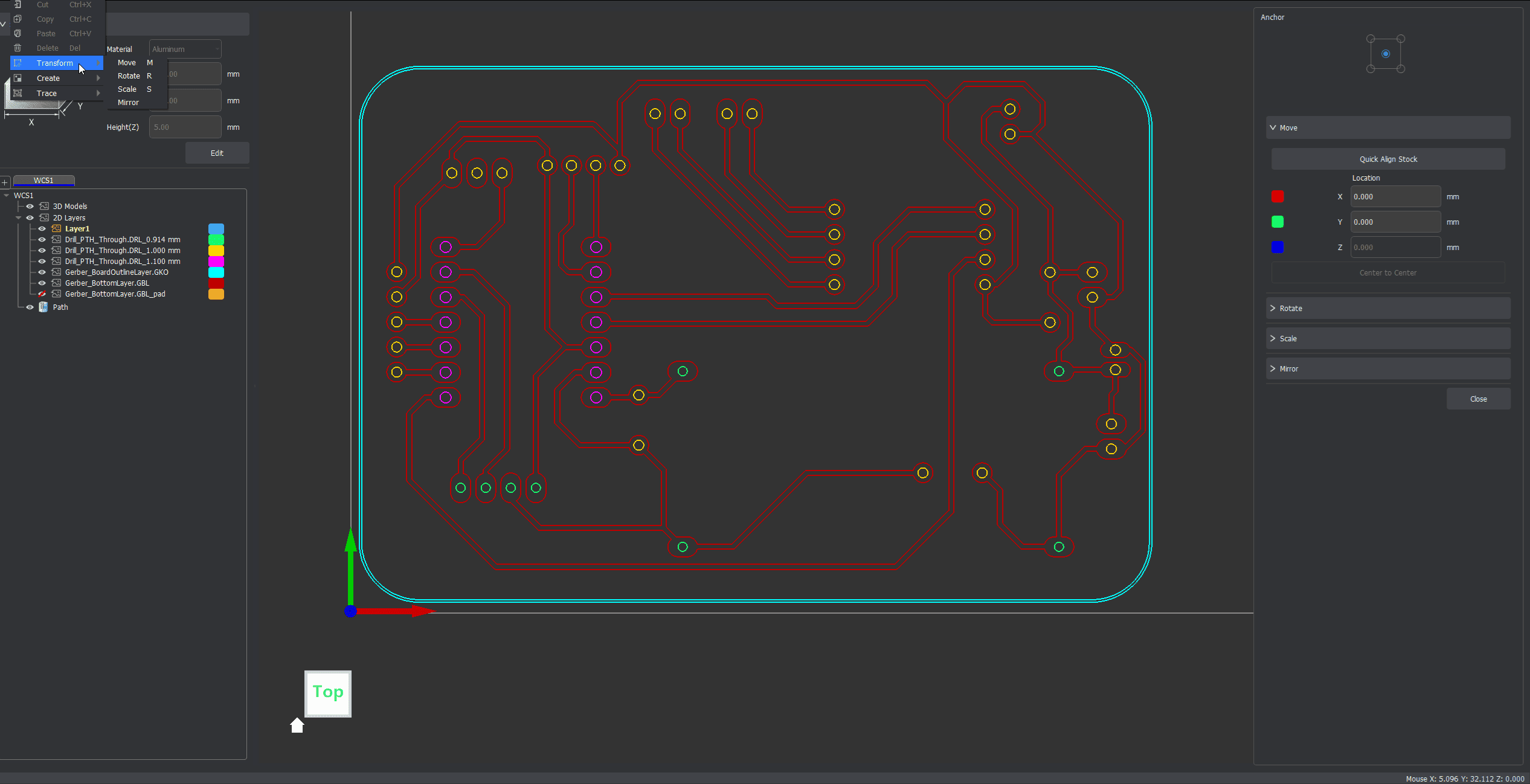
- PCB design → Wilken
- Gerbers → Wilken
Programming
- Firmware → Wilken
- Hardware integration → Wilken
Fabrication
- 3D printing → Jhonatan
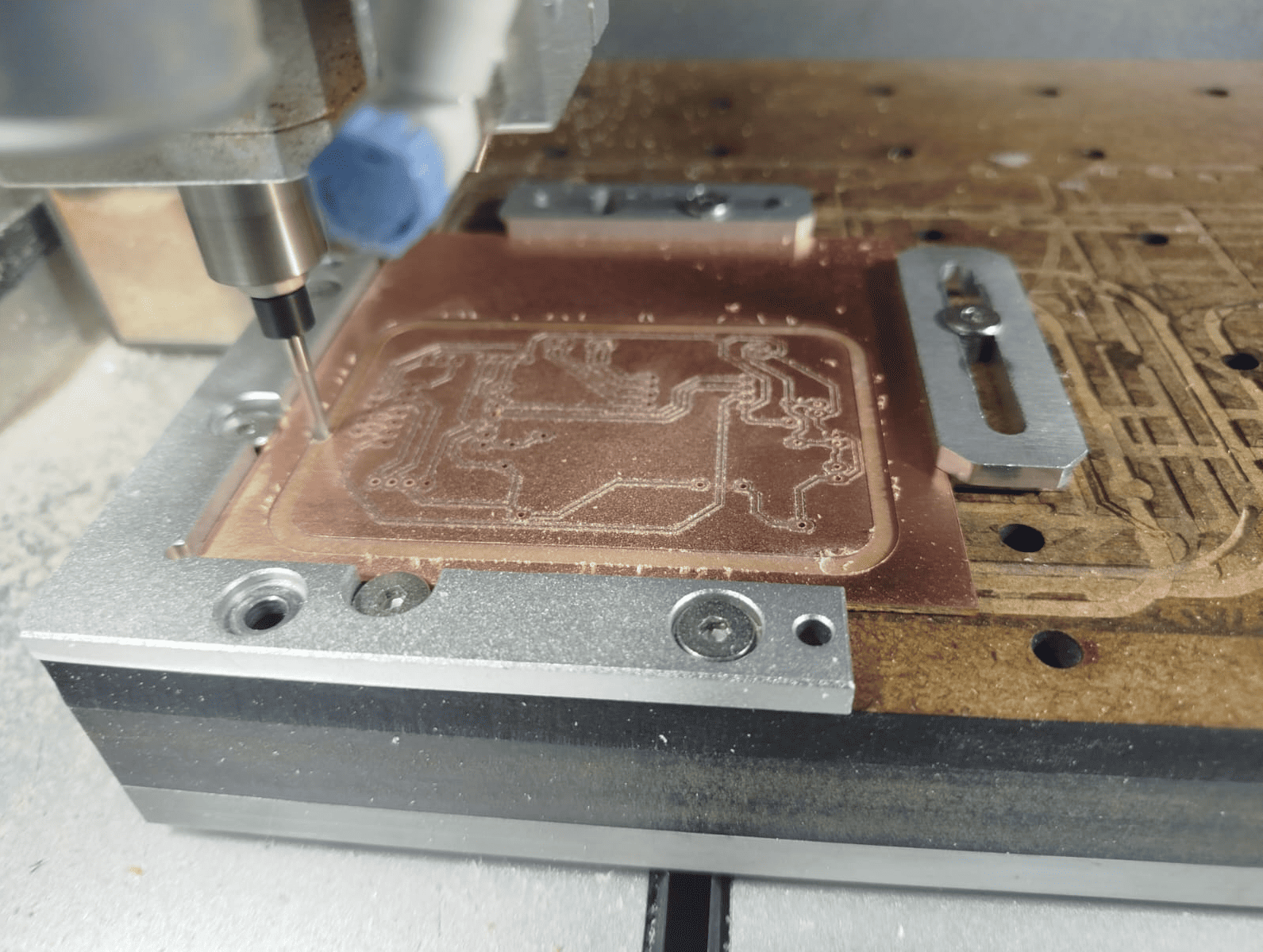
- PCB manufacturing → Jhonatan
- Assembly → Jhonatan
Integration & Testing
- Mechanical assembly → Both
- Electronics integration → Both
- Testing → Both
- Calibration → Both
Project Timeline – Gantt Chart
The development of the ReFill machine followed a structured schedule from April 9 to April 22, organizing tasks across design, fabrication, integration, and documentation phases.
The timeline allowed parallel development of mechanical, electronic, and software components, ensuring efficient progress and timely completion of the project.
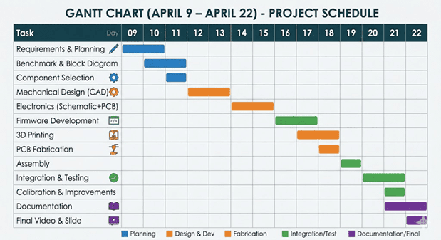
Gantt chart illustrating the planning and execution timeline of the ReFill project, including design, fabrication, integration, and final deliverables.
âš™ï¸ System Operation – How ReFill Works
The ReFill machine operates through an integrated system that combines mechanical motion, electronic control, and embedded programming. The control logic is based on a state machine, allowing the system to manage different operation modes in a structured and reliable way.
ðŸŽ›ï¸ User Input
Controlled using a rotary encoder with push button for navigation, start, reset, and parameter adjustment.
âš¡ Motor Actuation
A DC motor is driven using PWM control to ensure smooth filament rewinding.
📡 Feedback System
A hall-effect encoder measures rotation and calculates spool turns.
ðŸ–¥ï¸ Visual Interface
OLED display shows turns, target, system status, and menu.
🧠Control Logic – State Machine
- IDLE: Waiting for user input
- RUNNING: Motor rotates and counts turns
- CUTTING: Stops motor and activates cutter
🔄 Operation Workflow
- 1. Set target turns
- 2. Start process
- 3. Monitor rotation
- 4. Stop at target
- 5. Activate cutter
ðŸ›¡ï¸ Safety Features
- Limit switch protection
- Encoder feedback control
- Smooth PWM motor control
- Automatic stop
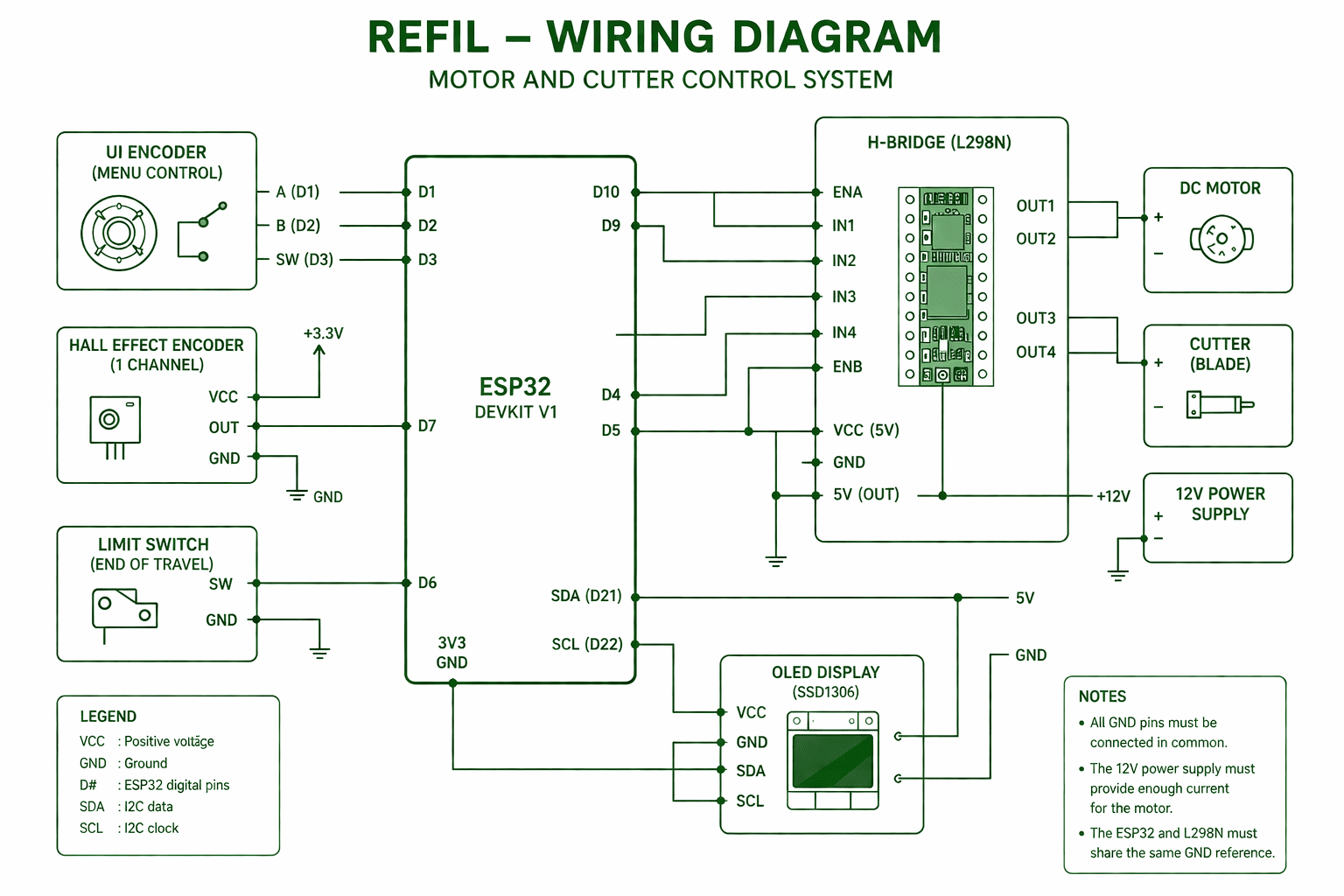
Electrical wiring diagram of the ReFill system including ESP32, H-bridge motor driver, encoders, and cutter mechanism.
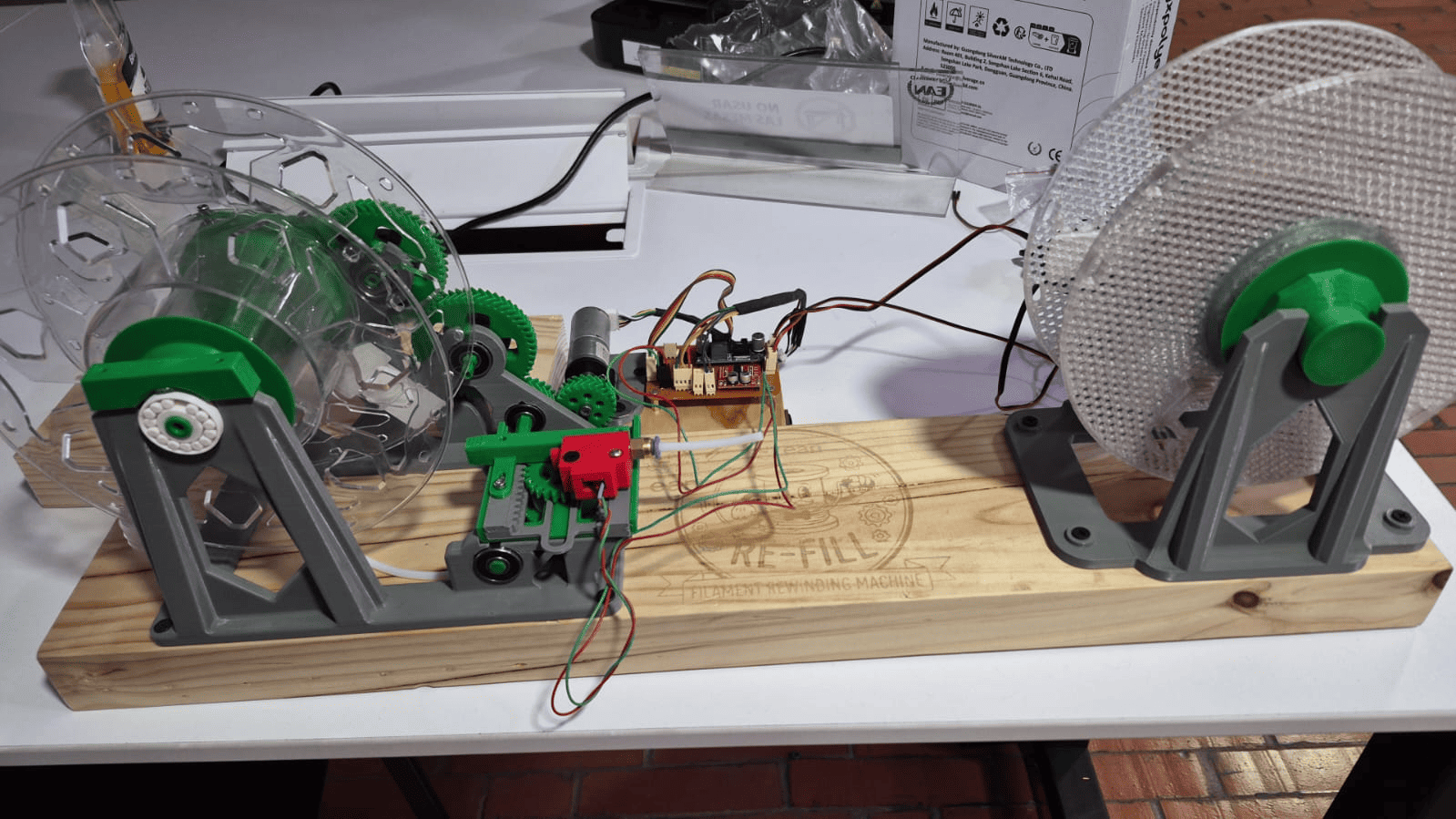
Mechanical Integration & Assembly
Once the electronic and control systems were completed, the next step was integrating them into the mechanical structure of the machine. The objective was to create a robust platform capable of supporting continuous filament rewinding while maintaining proper alignment, low friction, and reliable operation.
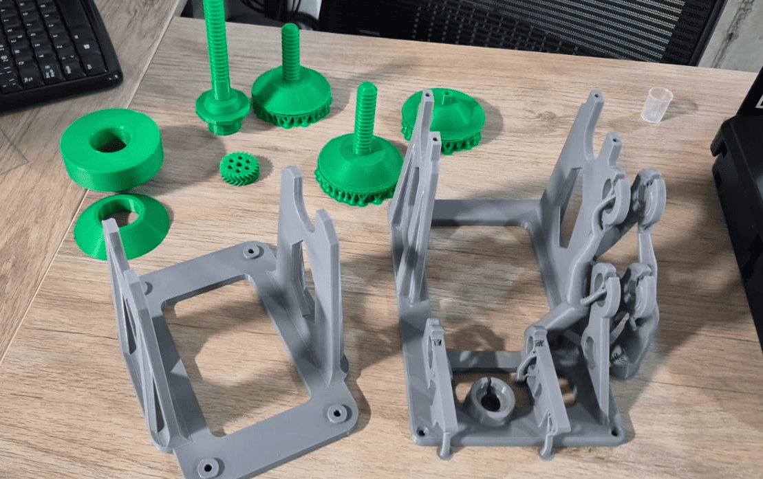
Most of the structural components were manufactured using FDM 3D printing. This approach allowed rapid iteration of the design while keeping fabrication costs low and enabling easy customization of each component according to the machine requirements.
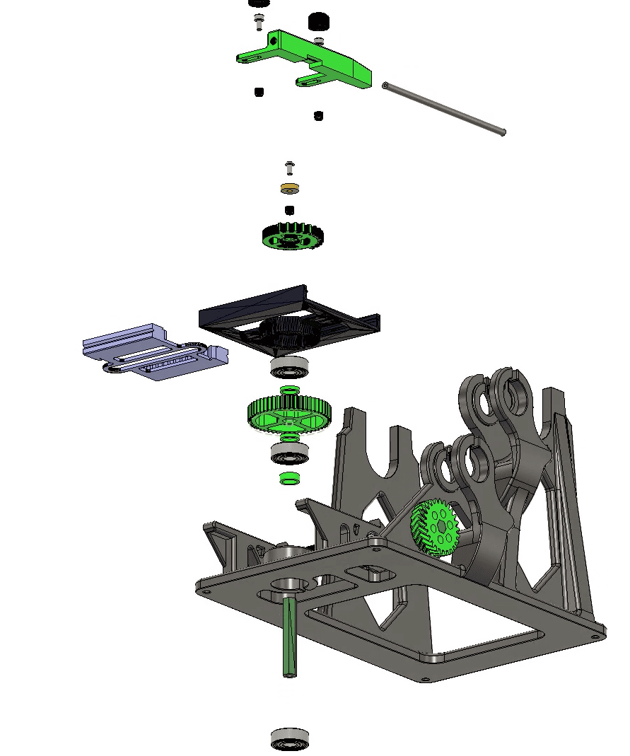
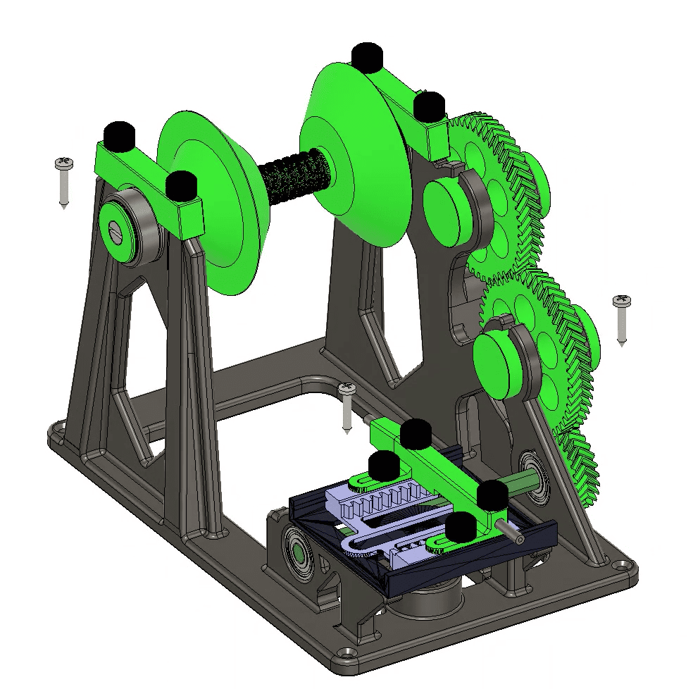
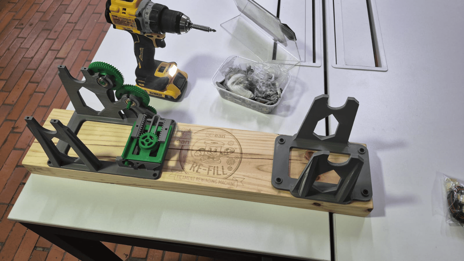
The printed parts included the main chassis, shaft supports, spool holders, transmission elements, and a complete set of herringbone gears. These gears were selected because their geometry improves load distribution and reduces axial forces during operation, resulting in smoother and more stable motion transfer.
Initial assembly of the printed mechanical components.
Structural Base
To provide rigidity and ensure proper alignment of the rotating elements, the entire assembly was mounted on a 1-inch thick wooden board. This base serves as the structural foundation of the machine and minimizes unwanted vibrations during operation.
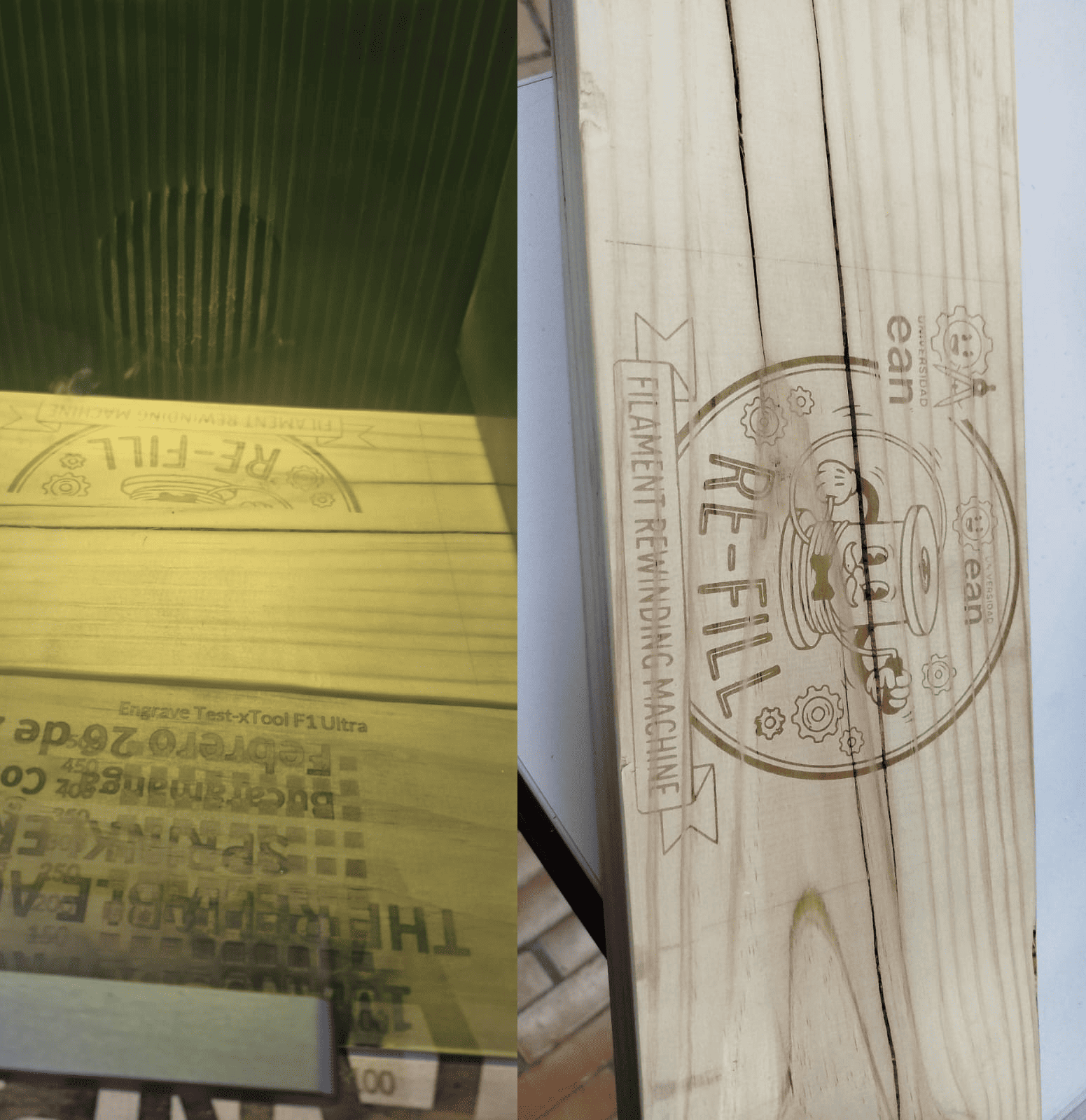
In addition to its structural role, the base was personalized with the project identity by engraving the ReFill logo using a laser cutter. This detail not only improved the aesthetics of the machine but also reinforced the project's branding and presentation.
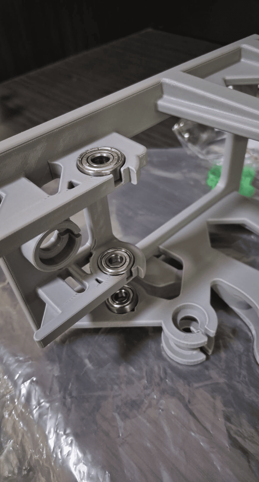
Bearing System
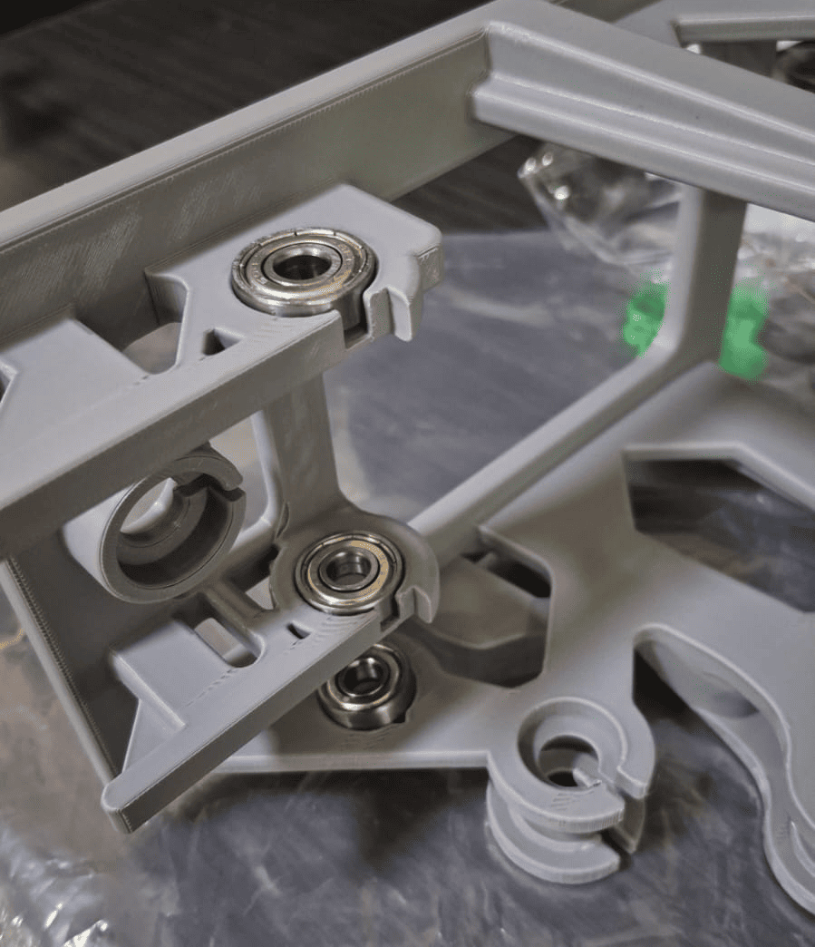
Bearing-supported shafts used to reduce friction and improve alignment.
A critical aspect of the design was minimizing friction between rotating components and their supports. To achieve this, the machine incorporates a total of eight 6006 ball bearings distributed across the different shafts.
The bearings significantly reduce rotational resistance while maintaining accurate shaft alignment. This solution prevents excessive stress on the printed PLA components and reduces the risk of wear, deformation, or dimensional changes over time.
By transferring mechanical loads from the plastic supports to the bearings, the overall durability and reliability of the system were greatly improved.
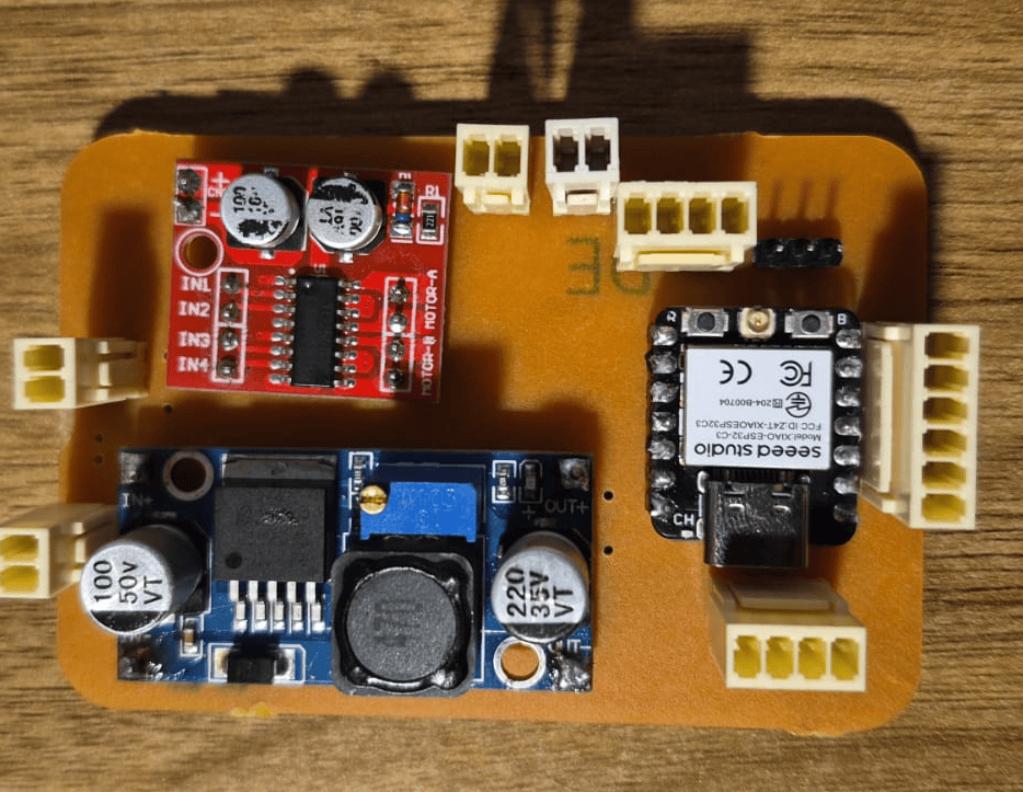
Power Distribution
The machine is powered by a 9V, 1.5A DC power adapter, selected to provide sufficient current for both the control electronics and the motor system.
For user safety and ease of operation, the power supply is connected through an external ON/OFF switch mounted directly on the machine. This arrangement allows the entire system to be energized or disconnected quickly without unplugging the power adapter.
The regulated voltage required by the electronics is then generated by the onboard LM2596 buck converter, ensuring stable operation of the ESP32 controller, OLED display, sensors, and peripheral devices.
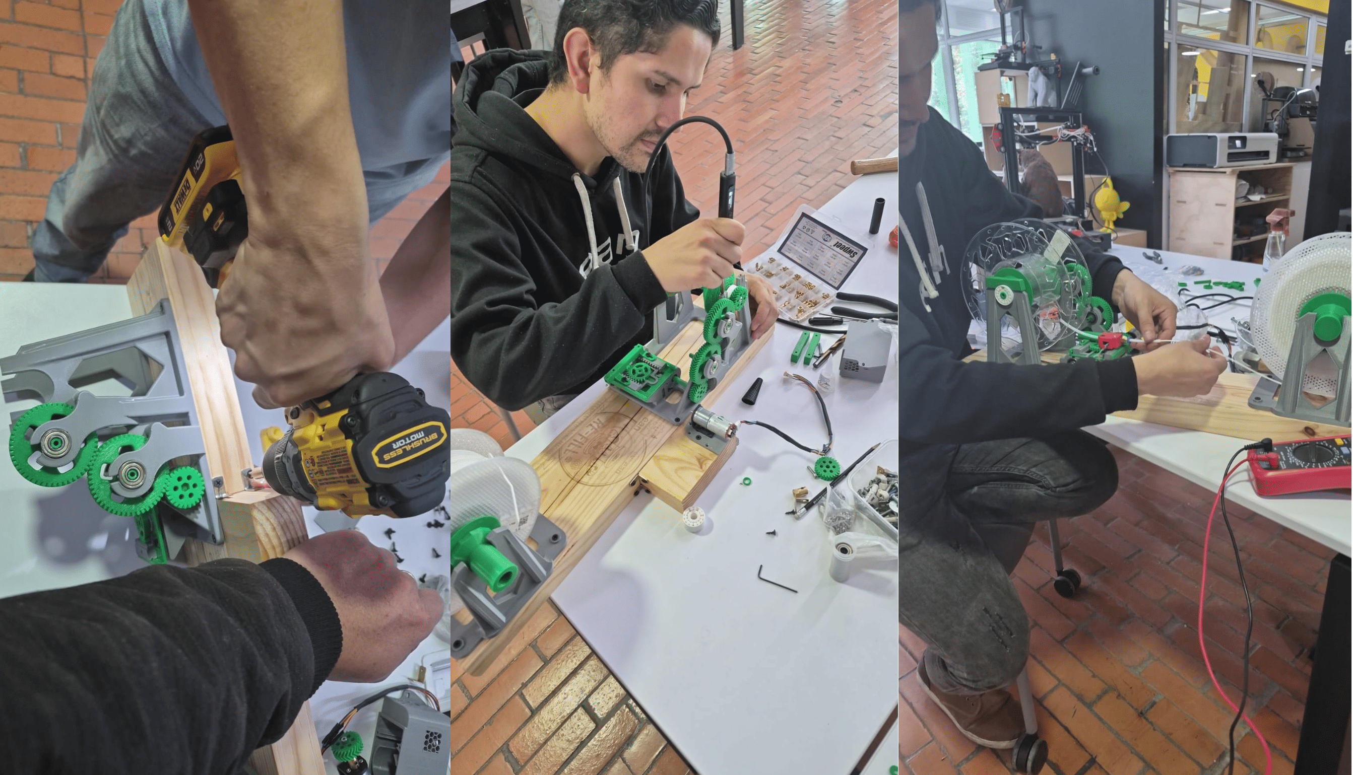
Manufacturing and Assembly Process
The following images summarize the fabrication, assembly, and integration process of the ReFill machine, from the production of individual components to the final functional prototype.
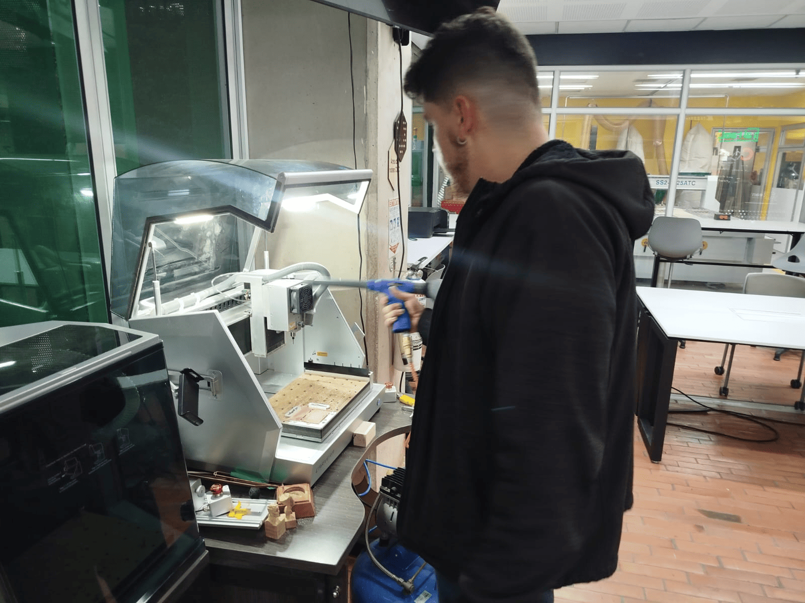
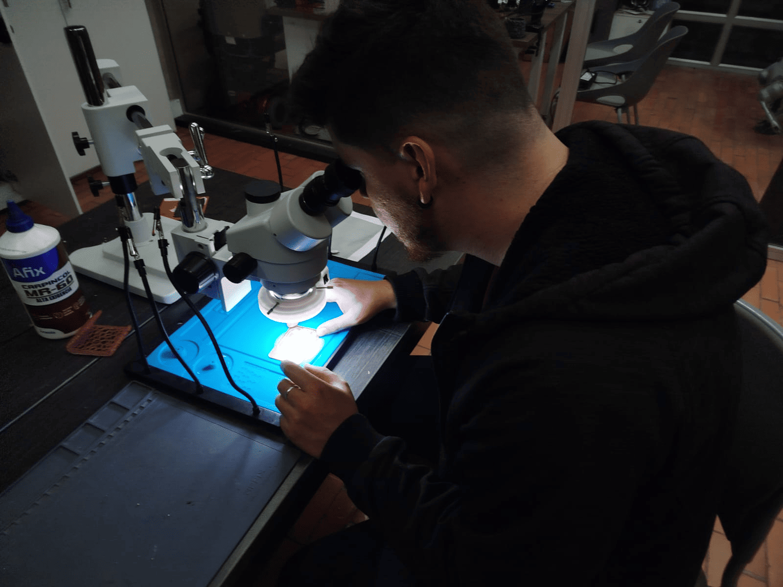
Component fabrication to final assembly and system validation.
Problems & Solutions
The development of the ReFill machine involved multiple iterations across mechanical, electronic, and programming domains. Throughout the process, several challenges emerged that required both practical and analytical problem-solving approaches. These issues were fundamental in understanding real-world fabrication constraints and improving the overall design.
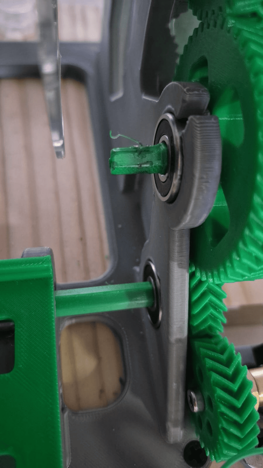
Mechanical Design – Tolerance Issues in 3D Printing
One of the main challenges encountered during the mechanical assembly was related to incorrect tolerance considerations in the 3D printed parts. Although the CAD design defined precise dimensions, the physical fabrication process introduced deviations due to printer accuracy, material expansion, and layer resolution.
This resulted in multiple components, particularly gear shafts and rotating elements, having an excessively tight fit. In some cases, the parts could not be assembled at all, while in others, rotation was blocked due to friction.
This issue highlighted a common mistake in digital fabrication: designing parts with ideal dimensions without considering manufacturing tolerances. In FDM 3D printing, even small deviations (0.1–0.3 mm) can significantly affect assembly performance.
Solution
To solve this issue, a manual post-processing approach was applied. Several parts were carefully sanded and adjusted to reduce friction and achieve proper clearance, especially in gear shafts.
While this solution allowed the system to function correctly, it also revealed the importance of incorporating tolerance offsets directly into the CAD design for future iterations.
Misalignment and tight fitting in 3D printed shaft components.
Manual sanding process applied to achieve proper tolerance.
Electronics – PCB Trace Damage During Soldering
During the PCB assembly process, an issue occurred when a copper trace was lifted while soldering one of the components. This caused a break in the electrical connection, preventing the circuit from functioning properly.
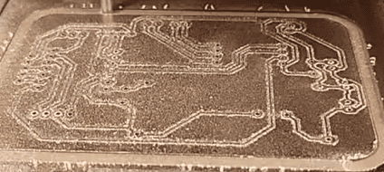
The problem was likely caused by a combination of excessive heat and mechanical stress applied during soldering. Since the PCB was fabricated using a milling process, the adhesion between copper and substrate can be weaker compared to industrial boards, making it more sensitive to damage.
Solution
Instead of redesigning and fabricating a new PCB, a practical repair solution was implemented. A small jumper wire was used to reconnect the damaged trace, restoring the electrical continuity of the circuit.
This approach allowed the system to function correctly while minimizing fabrication time, demonstrating the importance of rapid debugging and repair strategies in prototyping workflows.
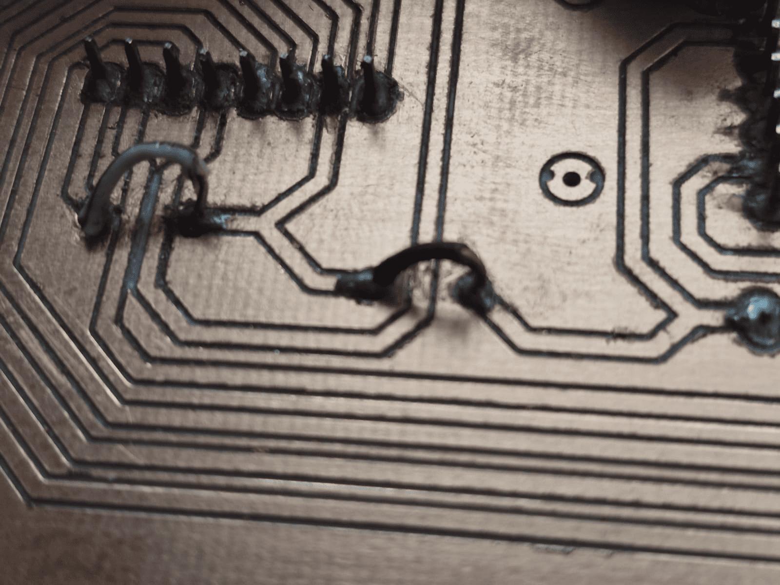
PCB repair using a jumper wire to restore a damaged trace.
Programming – Encoder Integration
The programming phase was relatively stable compared to mechanical and electronic challenges, as the firmware was built upon previously developed code from earlier assignments.
However, integrating motor encoders and user input control introduced additional complexity. Unlike simple motor control, encoder-based systems require precise signal reading and interpretation to provide accurate feedback.
Understanding how to correctly read encoder pulses, manage timing, and interpret direction required additional research and testing.
Solution
To address this, reference documentation and example implementations were studied in order to correctly integrate encoder reading into the control system. This allowed the system to improve its responsiveness and achieve more controlled filament movement.
Key Lessons Learned
- Design for manufacturing: always include tolerances in 3D printed parts
- Anticipate fabrication limitations in both mechanical and electronic design
- Develop practical repair strategies for rapid prototyping
- Reuse previous knowledge, but be prepared to research new system components
🚀 Future Improvements
While the ReFill machine successfully achieves its core functionality, several improvements were identified to enhance performance, reliability, and scalability in future iterations.
âš™ï¸ Mechanical Optimization
Future versions should include tolerance offsets directly in the CAD design to avoid post-processing and ensure smoother assembly and motion.
🔄 Filament cutter
Implement a Filament cutter system to finish the rewinding process with a clean cut, improving usability and reducing waste.
🎯 Tension Control
Add a tension control mechanism to prevent loose or overly tight winding and improve filament consistency.
🔌 Electronics Robustness
Improve PCB reliability with wider traces, better layout spacing, and protection components.
Final Reflection - Group Assignment
The development of the ReFill machine represented a comprehensive integration of mechanical design, electronics, and embedded programming. Throughout this project, the transition from digital design to physical implementation revealed important challenges that are not always evident during the conceptual phase.
One of the most significant learnings was understanding the gap between ideal CAD models and real-world fabrication. The tolerance issues encountered during 3D printing demonstrated that even small dimensional variations can directly affect system performance. This emphasized the importance of designing with manufacturing constraints in mind.
In the electronics domain, the PCB fabrication and assembly process highlighted the fragility of milled boards and the importance of careful handling during soldering. The need to repair a damaged trace reinforced the value of practical problem-solving skills and adaptability during prototyping.
From a programming perspective, the project demonstrated the advantage of building upon previous work. Reusing code from earlier assignments accelerated development, allowing more focus on system integration. However, integrating encoder feedback required additional research, reinforcing the importance of continuous learning when working with more complex control systems.
Another key aspect of this project was teamwork. The clear distribution of responsibilities between mechanical design, electronics, and programming enabled efficient progress and parallel development. Collaboration during integration and testing phases was essential to ensure that all subsystems functioned correctly as a unified machine.
Overall, this project highlighted a fundamental principle of digital fabrication: successful systems are not only the result of good design, but also of iterative testing, problem-solving, and adaptation to real-world constraints. The ReFill machine is not only a functional tool, but also a reflection of this learning process.
Downloads & Resources
This section provides access to the design resources and downloadable files developed for the ReFill Machine. The repository includes the complete mechanical design, electronics, firmware, and supporting documentation required to reproduce the system.
🛠️ Project Resources
The project combines mechanical engineering, electronics, and embedded programming into a single machine. The repository includes every design file required for fabrication, assembly, and system operation.
- ✅ Mechanical CAD Models (3MF)
- ✅ PCB Design & Gerber Files
- ✅ Embedded Firmware Source Code
- ✅ Mechanical Assembly Resources
- ✅ Manufacturing Documentation
- ✅ Project Assets & Supporting Files
📁 Downloadable Files
To improve the loading performance of this documentation website, all project files have been moved to a shared Google Drive folder.
The repository contains the complete mechanical design, PCB fabrication files, embedded firmware, manufacturing resources, and supporting documentation developed for the ReFill Machine.
Future hardware revisions, firmware updates, and additional documentation may be added as the project continues to evolve.