Individual Assignment
- Write an application for the embedded board that interfaces a user with input and/or output devices.
Learning Outcomes
- Implement a User Interface (UI) using programming.
- Explore communication protocols between a custom microcontroller board and a desktop application.
- Develop real-time interaction between software and embedded hardware systems.
Progress Status - Embedded Interface Application
Development of a desktop monitoring and control system using Java Swing, UART communication, and a custom ESP32-C3 embedded board.
Integration and programming of the custom ESP32-C3 PCB including DHT22 sensor, SSD1306 OLED display, and relay-based room lighting control.
Design and organization of graphical components in Java Swing, including status indicators, environmental monitoring panels, and interactive control elements.
Bidirectional serial communication implemented using Java JSerialComm and Arduino Serial protocol for real-time data exchange.
Real-time visualization of temperature and humidity values using the DHT22 sensor, desktop GUI, and OLED display synchronization.
Remote ON/OFF room light control using a relay module connected Normally Open (NO) and controlled directly from the Java interface.
System Demonstration
The following demonstration shows the complete operation of the embedded monitoring and control system, including UART communication, environmental monitoring, OLED visualization, and relay-based room lighting control through the Java Swing desktop application.
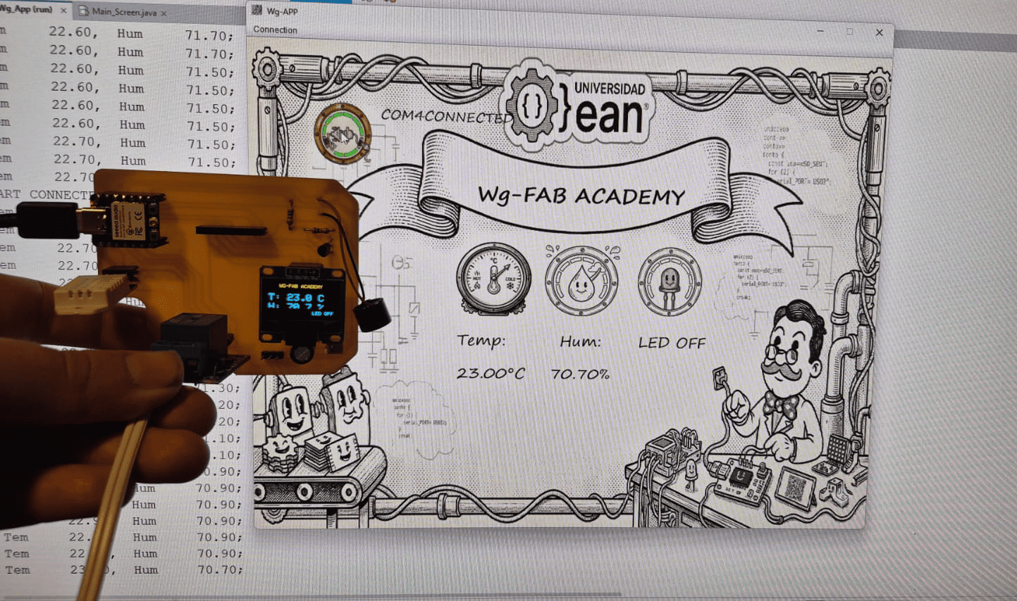
HeroShot: Complete embedded monitoring and control platform showing the Java Swing interface, ESP32-C3 system, OLED display, DHT22 sensor, and relay-based lighting control operating in real time.
Real-time interaction between the Java Swing interface and the ESP32-C3 embedded system using UART communication.
Context & System Overview
This assignment focuses on the development of a desktop application capable of communicating with a custom embedded system through the UART protocol. The project integrates both software and hardware components, allowing real-time monitoring of environmental variables and remote control of physical devices.
The graphical user interface was developed using Java Swing inside the NetBeans IDE. NetBeans provides an integrated graphical interface designer that simplifies the organization of visual components while still allowing full access to the application source code.
Using Swing made it possible to create a custom desktop interface composed of interactive elements such as icons, status indicators, environmental monitoring labels, connection management menus, and relay control buttons. The event-driven programming model also enabled real-time interaction between the GUI and the embedded system.
The embedded hardware platform used in this assignment was the custom ESP32-C3 PCB previously designed and fabricated during the Electronics Production week. The board integrates the XIAO ESP32-C3 microcontroller and provides the main communication and control interface for the sensors and actuators connected to the system.
The system includes:
- DHT22 sensor for temperature and humidity monitoring
- SSD1306 OLED display for local visualization
- Relay module for room light control
- UART serial communication between Java and ESP32-C3
Environmental data is acquired by the microcontroller, transmitted through UART, processed by the Java application, and displayed simultaneously on both the desktop interface and the OLED display. Additionally, the GUI can send commands back to the ESP32-C3 to remotely control the relay-connected lamp.
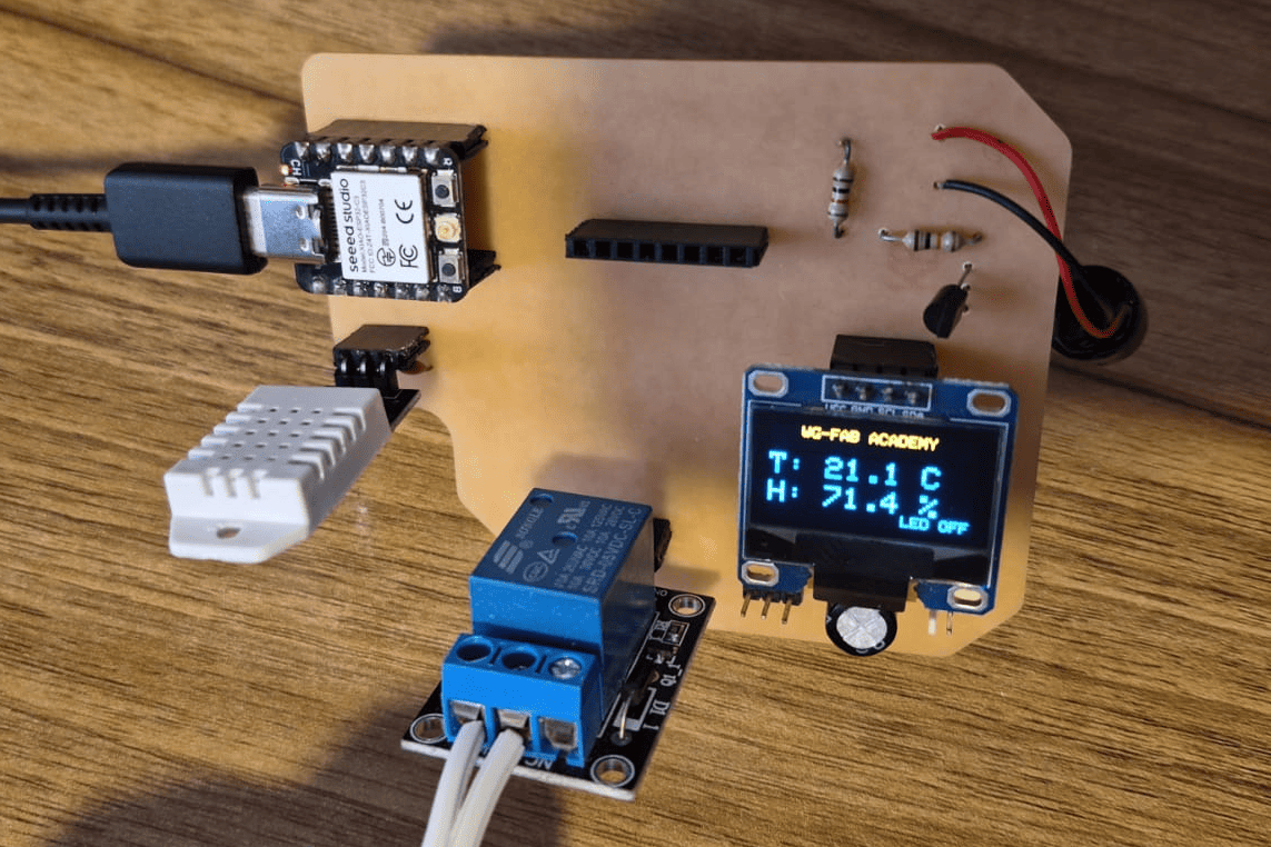
Custom ESP32-C3 PCB developed during the Electronics Production week, used as the embedded hardware platform for this assignment.
Simulation Validation - Wokwi
Before implementing the circuits on physical hardware, all experiments were first simulated using Wokwi. This allowed me to validate both the code logic and the behavior of the output devices in a controlled environment.
Through simulation, I was able to perform early debugging, verify pin configurations, and test different control strategies such as PWM signals for the servo motor and buzzer, as well as I2C communication for the OLED display.
This approach significantly reduced development time and minimized the risk of hardware errors, such as incorrect wiring or unstable signal behavior. It also provided a better understanding of how different output devices respond to microcontroller commands.
Using simulation as a first step helped ensure that each output device behaved correctly before integrating it into the final physical system based on the custom PCB.
Embedded System and UART Communication
The embedded system was developed using the custom ESP32-C3 PCB designed during the Electronics Production week. The board integrates environmental sensing, local visualization, and actuator control capabilities through a unified hardware architecture.
The system uses a DHT22 sensor to measure temperature and humidity, an SSD1306 OLED display for local real-time visualization, and a relay module connected in Normally Open (NO) configuration to control the ON/OFF state of a room lamp.
UART Communication Protocol
Communication between the desktop application and the embedded board was implemented using the UART serial protocol. The ESP32-C3 continuously transmits environmental data through the serial interface, while the Java application sends control commands back to the microcontroller.
On the embedded side,
communication was implemented using the
Arduino Serial library,
while the desktop application uses
the JSerialComm Java library
for serial port management and asynchronous data reading.
System Behavior
- DHT22 sensor measures temperature and humidity
- ESP32-C3 sends data through UART
- Java Swing GUI displays real-time values
- OLED display mirrors environmental information locally
- GUI sends relay control commands (LON / LOFF)
- ESP32-C3 activates or deactivates the relay output
Embedded monitoring and control system using ESP32-C3, DHT22 sensor, SSD1306 OLED display, and relay module.
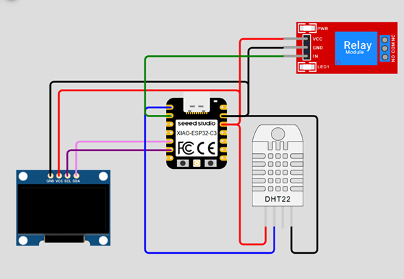
Circuit Connection
- VCC → 3.3V
- GND → GND
- DATA → D0
- VCC → 3.3V
- GND → GND
- SDA → SDA
- SCL → SCL
- VCC → 5V
- GND → GND
- IN → D1
- COM → AC Line
- NO → Lamp
Embedded Program Code
#include <Wire.h>
#include <Adafruit_GFX.h>
#include <Adafruit_SSD1306.h>
#include <DHT.h>

// ================= PINOUT =================
#define DHTPIN  D0
#define DHTTYPE DHT22

#define LED     D1

// ================= DHT =================
DHT dht(DHTPIN, DHTTYPE);

// --SSD1306--
#define height 64
#define width 128
#define rst -1

Adafruit_SSD1306 display(width, height, &Wire, rst);

//================ Variables ================
float tem = 0.0;
float hum = 0.0;

void setup() {

  pinMode(LED, OUTPUT);

  Serial.begin(115200);

  Wire.begin();

  dht.begin();

  if (!display.begin(SSD1306_SWITCHCAPVCC, 0X3C)) {

    Serial.println("Oled Display NOT Found...");

    for (;;);
  }

  printTxt("Control");

  delay(3000);

  digitalWrite(LED, LOW);

  printTxt("OFF");
}

void loop() {

  // ===== READ DHT22 =====
  tem = dht.readTemperature();
  hum = dht.readHumidity();

  // ===== VALIDATE =====
  if (isnan(tem) || isnan(hum)) {

    Serial.println("DHT ERROR");

    delay(1000);

    return;
  }

  // ===== SEND SERIAL DATA =====
  Serial.print("Tem\t");

  Serial.print(tem);

  Serial.print(",\tHum\t");

  Serial.print(hum);

  Serial.println(";");

  // ===== PRINT DATA ON DISPLAY =====
  printData(tem, hum, digitalRead(LED));

  // ===== SERIAL COMMANDS =====
  if (Serial.available() > 0) {

    String txt = Serial.readString();

    txt.trim();

    if (txt == "LON") {

      digitalWrite(LED, HIGH);

      printTxt("ON");
    }
    else if (txt == "LOFF") {

      digitalWrite(LED, LOW);

      printTxt("OFF");
    }
  }

  delay(1000);
}
Code Explanation
-
System Initialization and Peripheral Configuration:
The program initializes multiple hardware subsystems during the
setup()function, including UART communication, I2C communication, the DHT22 sensor, the OLED display, and the relay output pin. The ESP32-C3 acts as the central controller, coordinating sensor acquisition, graphical visualization, and actuator control simultaneously. -
UART Communication using Serial Protocol:
The communication between the embedded board
and the Java Swing application
is implemented through the UART serial protocol using
the Arduino
Seriallibrary. The instruction:
configures the serial interface at 115200 baud, enabling high-speed bidirectional communication between the ESP32-C3 and the desktop application. Environmental data is periodically transmitted, while control commands such asSerial.begin(115200);LONandLOFFare received from the GUI. -
DHT22 Environmental Sensor Reading:
The DHT22 sensor is used to measure both temperature
and relative humidity.
The instructions:
retrieve environmental values directly from the sensor. Since DHT sensors are relatively slow and sensitive to timing, the library internally manages communication timing and checksum validation.tem = dht.readTemperature(); hum = dht.readHumidity(); -
Sensor Validation and Error Detection:
Sensor readings are validated using:
The functionif (isnan(tem) || isnan(hum))isnan()verifies whether the sensor returned invalid numerical values. If an error occurs, the system sends a diagnostic message through UART and skips the current iteration, preventing corrupted data from propagating into the graphical interface. -
Formatted Serial Data Transmission:
Environmental information is transmitted using
a structured serial message format:
This formatting strategy simplifies parsing inside the Java application, where the incoming UART stream is processed character by character. The semicolon (Tem 25.5, Hum 60.0;;) acts as an end-of-message delimiter, allowing synchronization between the embedded system and the desktop application. -
OLED Display Rendering using I2C:
The SSD1306 OLED display communicates through
the I2C protocol using the
Wirelibrary. The display provides local real-time feedback, allowing the embedded system to operate independently even without the desktop application connected. The rendering process follows a buffered graphics approach: graphical elements are first written into memory and later transferred to the display usingdisplay.display(), minimizing flickering effects. -
Relay Control Logic:
The relay module is connected in Normally Open (NO)
configuration and controlled through a digital GPIO pin.
When the application receives:
the relay output is activated:LON
and the room lamp turns ON. Similarly, the command:digitalWrite(LED, HIGH);
deactivates the relay and disconnects the load.LOFF -
Bidirectional Human-Machine Interaction:
The system demonstrates a complete bidirectional
communication workflow:
- Embedded system → sends environmental data
- Desktop application → displays real-time monitoring
- User interaction → triggers control commands
- ESP32-C3 → actuates the relay output
-
Integrated Embedded System Architecture:
The final program integrates multiple subsystems simultaneously:
- Environmental sensing (DHT22)
- Graphical local visualization (SSD1306)
- UART communication
- Desktop GUI interaction
- Relay-based actuator control
loop()function continuously executes all these processes, creating a synchronized real-time monitoring and control platform.
Java Swing GUI Development
The desktop application was developed using Java Swing, a graphical user interface (GUI) toolkit included in the Java Foundation Classes (JFC). Swing provides a complete set of graphical components that allow developers to create desktop applications using an object-oriented and event-driven programming model.
Unlike low-code platforms, Swing applications are built entirely through code, giving full control over interface behavior, graphical customization, event management, and hardware integration. Since Swing is part of Java, applications can run across multiple operating systems through the Java Virtual Machine (JVM).
In this project, Swing was used to create a real-time monitoring and control interface connected to the ESP32-C3 embedded system through UART communication. The application includes graphical indicators, serial configuration menus, environmental monitoring panels, and relay control interaction.
Swing Components Used
| Component | Purpose | Role in the Project |
|---|---|---|
JFrame |
Main application window | Acts as the main desktop interface container |
JPanel |
Graphical container | Used to organize interface sections and render custom backgrounds |
JLabel |
Text and image display | Displays sensor values, icons, and interactive graphics |
JMenu |
Menu creation | Creates UART configuration menus |
JRadioButtonMenuItem |
Selectable options | Allows baud rate and serial parameter selection |
ButtonGroup |
Selection management | Ensures only one UART option is selected at a time |
JButton |
Standard button interaction | Evaluated during development but replaced by labels for aesthetics |
Project Creation Workflow
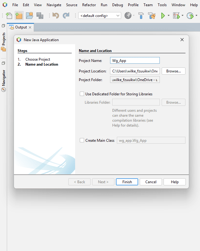
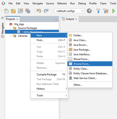
Creation of the Java Application project inside NetBeans.
Creating the Java Project
The first step consisted of creating a standard Java Application project inside NetBeans. This automatically generates the project structure, source folders, build configuration, and dependency management required by the application.
NetBeans simplifies project organization by separating:
- Source code files
- Resources and images
- Libraries and dependencies
- Build and execution configuration
This modular structure is especially useful for medium and large desktop applications.
Creating the JFrame Interface
After creating the project,
a JFrame Form was added.
A JFrame represents the main application window
and acts as the root container
for all graphical components.
Swing interfaces are constructed hierarchically, where graphical components are placed inside containers such as panels and frames.
NetBeans automatically generates part of the interface code, including:
- Component initialization
- Graphical layout configuration
- Object declarations
- Event listener structures
This reduces repetitive coding tasks while still allowing manual customization.
Creation of the JFrame form used as the main application window.
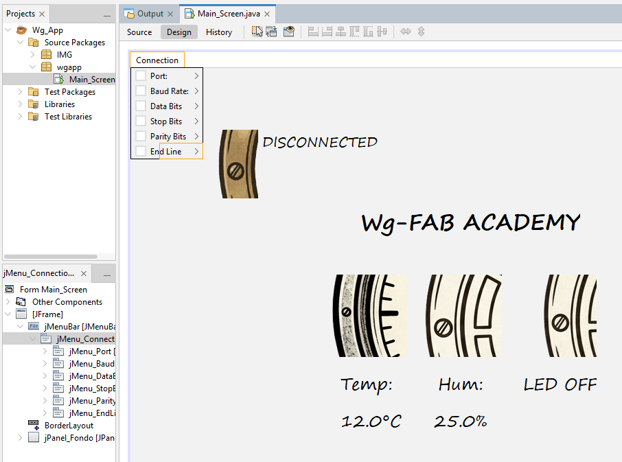
Graphical positioning of Swing components using the NetBeans editor.
GUI Layout and Component Positioning
The NetBeans GUI editor provides a visual drag-and-drop interface that allows components to be positioned interactively.
During this stage, the application layout was organized into:
- Environmental monitoring indicators
- Connection status section
- Relay control interface
- UART configuration menus
- Custom background graphics
Several graphical attributes were configured manually, including:
- Fonts and text sizes
- Object alignment
- Foreground colors
- Transparent backgrounds
- Image scaling
- Custom icons
This process allowed the interface to achieve a more personalized appearance compared to default Swing applications.
Final Interface Preview
The final application integrates graphical monitoring, serial communication, and hardware interaction inside a unified desktop interface.
One important design decision
was the use of JLabel components
instead of traditional JButton objects
for interactive controls.
Although buttons provide native interaction behavior, labels make it easier to display and scale images without default button borders or styling.
This allowed the interface to use graphical icons as interactive elements, producing a cleaner and more visually integrated design.
The application also dynamically changes icons to represent system states such as:
- Connected / Disconnected status
- Relay ON / OFF state
- Environmental indicators
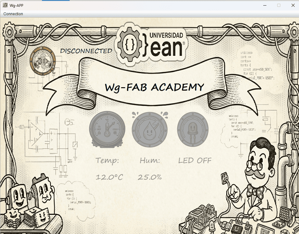
Final Java Swing interface used for real-time monitoring and relay control.
UART Communication in Java
One of the most important parts of this project was the implementation of bidirectional UART communication between the Java Swing application and the ESP32-C3 embedded system.
Unlike Arduino IDE environments where serial communication is handled automatically, desktop applications require direct management of serial ports, communication parameters, asynchronous data reading, event listeners, and exception handling.
To implement this communication layer, the project uses the JSerialComm library, which provides cross-platform serial communication support for Java.
Libraries Used
| Library | Purpose |
|---|---|
com.fazecast.jSerialComm |
UART serial communication management |
javax.swing |
Graphical user interface components |
java.io.OutputStream |
Sending serial data to the ESP32-C3 |
java.awt |
Graphics and image management |
SerialPort Object Creation
private SerialPort serialComm;
private OutputStream output;
The SerialPort object represents
the physical UART communication interface.
This object is responsible for:
- Opening and closing COM ports
- Configuring serial parameters
- Sending and receiving data
- Managing communication events
The OutputStream object is used
to transmit bytes directly to the ESP32-C3 board.
Automatic COM Port Detection
The application dynamically scans all available serial ports connected to the operating system.
Each detected COM port is automatically converted into a selectable menu option inside the GUI.
This allows the application to adapt dynamically when USB devices are connected or disconnected.
for (SerialPort p : SerialPort.getCommPorts()) {
JRadioButtonMenuItem menuPort =
new JRadioButtonMenuItem();
menuPort.setText(
p.getSystemPortName()
);
this.Port_Group.add(menuPort);
this.jMenu_Port.add(menuPort);
this.portList.add(menuPort);
}
UART Communication Parameters
this.serialComm.setBaudRate(this.baudRate);
this.serialComm.setNumDataBits(this.dataBits);
this.serialComm.setNumStopBits(this.stopBits);
this.serialComm.setParity(this.parityBits);
UART communication requires several synchronized parameters between the ESP32-C3 and the desktop application.
- Baud Rate: transmission speed
- Data Bits: size of transmitted data packets
- Stop Bits: frame synchronization
- Parity: error checking mechanism
These parameters are configurable directly from the GUI menus, allowing the application to support multiple serial configurations.
The default configuration used in this project is:
- 115200 baud
- 8 data bits
- 1 stop bit
- No parity
Asynchronous Serial Event Listener
One of the most important features of JSerialComm is its event-driven communication model.
Instead of continuously polling the serial port,
the application uses a
SerialPortDataListener
that automatically triggers
whenever new data arrives.
This asynchronous approach improves efficiency and enables real-time GUI updates without blocking the application thread.
activePort.addDataListener(
new SerialPortDataListener() {
@Override
public int getListeningEvents() {
return SerialPort
.LISTENING_EVENT_DATA_RECEIVED;
}
@Override
public void serialEvent(
SerialPortEvent event
) {
byte[] newData =
event.getReceivedData();
}
});
UART Data Processing
if (c == '\n') {
String msg =
dataBuffer.toString().trim();
SwingUtilities.invokeLater(() -> {
dataLabelProcess(msg);
});
dataBuffer.setLength(0);
}
Incoming UART data is received byte-by-byte
and accumulated inside a
StringBuilder buffer.
When the newline character is detected, the complete message is processed.
The method:
SwingUtilities.invokeLater()ensures that GUI components are updated safely inside the Swing Event Dispatch Thread (EDT), preventing concurrency problems during real-time interface updates.
Sensor Data Parsing
The ESP32-C3 sends structured messages containing temperature and humidity values.
The application validates the message format, separates the variables, extracts numerical values, and updates the interface dynamically.
This parsing stage acts as a simple communication protocol layer between hardware and software.
if(msg.charAt(0) == 'T' &&
msg.charAt(msg.length()-1) == ';') {
String[] variables = msg.split(",");
this.jLabel_TemVal
.setText(variables[0] + "°C");
this.jLabel_HumVal
.setText(variables[1] + "%");
}
Sending Commands to the ESP32-C3
private void sendData(String txt) {
txt += this.endLine;
this.output.write(txt.getBytes());
}
Communication is fully bidirectional.
The GUI can send commands such as:
LON→ Relay ONLOFF→ Relay OFF
These commands are converted into byte arrays and transmitted through the UART interface directly to the ESP32-C3.
End-line characters can also be configured dynamically using the GUI menus, supporting:
- No terminator
- New Line (\n)
- Carriage Return (\r)
- Both (\r\n)
Exception Handling
Serial communication is highly dependent on external hardware availability.
For this reason, the application includes multiple exception handling mechanisms to prevent crashes during:
- Disconnected devices
- Invalid COM port selection
- Communication failures
- I/O transmission errors
Error dialogs are displayed using
JOptionPane,
allowing the user to identify problems quickly.
catch (Exception e2) {
JOptionPane.showMessageDialog(
this,
e2,
"ERROR",
JOptionPane.ERROR_MESSAGE
);
this.enableTools();
}
Environmental Monitoring
One of the main functionalities of the application is the real-time monitoring of environmental variables using a DHT22 sensor connected to the ESP32-C3.
The system continuously measures:
- Ambient temperature
- Relative humidity
These values are transmitted through UART, processed inside the Java application, and dynamically displayed in the graphical interface using Swing labels and graphical indicators.
Reading Environmental Data from the ESP32-C3
tem = dht.readTemperature();
hum = dht.readHumidity();
The DHT22 sensor is responsible for measuring ambient temperature and relative humidity.
The ESP32-C3 periodically reads the sensor values using the DHT library, which internally handles timing synchronization and checksum validation required by the protocol.
The measured values are stored in floating-point variables and later transmitted to the Java application through UART communication.
Serial Transmission Format
The ESP32-C3 sends environmental data using a structured serial message format.
This formatting is important because it allows the Java application to identify, separate, and process incoming variables correctly.
The semicolon character acts as an end-of-message marker, while the comma separates temperature and humidity values.
Serial.print("Tem\t");

Serial.print(tem);

Serial.print(",\tHum\t");

Serial.print(hum);

Serial.println(";");
Message Validation and Parsing
if(msg.charAt(0) == 'T' &&
   msg.charAt(msg.length()-1) == ';') {

    String[] variables = msg.split(",");
}
Once the UART message arrives, the Java application validates whether the received data matches the expected protocol structure.
The program verifies:
- Correct initial character
- Correct message termination
- Presence of both variables
After validation, the message is divided into two sections using the comma separator.
Numerical Data Extraction
The incoming UART message contains both text and numerical information.
To isolate the sensor values, the application iterates character-by-character through the received string, extracting only valid numerical symbols.
This filtering process removes:
- Text labels
- Tabs and spaces
- Special formatting characters
The result is a clean numerical value ready to be displayed inside the GUI.
for(char c : variables[n].toCharArray()) {

    if(Character.isDigit(c) ||
       c == '.' ||
       c == '-') {

        aux += c;
    }
}
Dynamic JLabel Update
this.jLabel_TemVal
    .setText(variables[0] + "°C");

this.jLabel_HumVal
    .setText(variables[1] + "%");
One of the most important mechanisms in the interface is the dynamic modification of Swing labels using the method:
setText()
In Swing,
a JLabel is a graphical object
capable of displaying text or images.
The method:
setText()allows the content of the label to be updated in real time while the application is running.
This mechanism transforms the GUI into a live monitoring dashboard, where environmental values are refreshed continuously as new UART data arrives from the ESP32-C3.
Without this dynamic update capability, the interface would only display static information.
Thread-Safe GUI Updates
Since serial communication events occur asynchronously, GUI updates cannot be executed directly from the serial communication thread.
Swing requires graphical updates to be executed inside the Event Dispatch Thread (EDT) to prevent concurrency problems.
For this reason, the project uses:
SwingUtilities.invokeLater()which safely schedules the interface update inside the correct graphical thread.
SwingUtilities.invokeLater(() -> {

    dataLabelProcess(msg);

});
Real-Time Monitoring System
if(msg == null || msg.isEmpty()) {
    return;
}
The monitoring system operates continuously while validating incoming data in real time.
Before processing any message, the application verifies:
- That data actually exists
- That the message is not empty
- That the format is correct
This prevents corrupted UART messages from generating interface errors or invalid sensor readings.
The result is a stable real-time monitoring platform capable of continuously synchronizing the embedded system with the desktop GUI.
Relay Lighting Control
In addition to environmental monitoring, the application also implements remote actuator control through a relay module connected to the ESP32-C3.
The relay operates in Normally Open (NO) configuration and is used to control the ON/OFF state of a room lamp directly from the Java Swing interface.
This creates a complete Human-Machine Interface (HMI) where the desktop application can both:
- Monitor environmental variables
- Control physical hardware remotely
Interactive JLabel as a Control Element
jLabel_LedImg.addMouseListener(
    new java.awt.event.MouseAdapter() {

    public void mouseClicked(
        java.awt.event.MouseEvent evt
    ) {

        jLabel_LedImgMouseClicked(evt);
    }
});
Instead of using a traditional
JButton,
the application uses a clickable
JLabel
as the relay control interface.
The label behaves as a graphical button
by attaching a
MouseListener
event to the image component.
This approach provides greater visual customization because labels allow images to be displayed naturally without default Swing button borders, focus indicators, or platform-specific styles.
As a result, the interface achieves a cleaner and more modern visual appearance.
Dynamic Icon Switching
One of the most important visual features of the interface is the dynamic replacement of icons according to the relay state.
When the user clicks the graphical label, the application changes:
- The displayed image
- The status text
- The internal boolean state
This creates immediate visual feedback, allowing the user to understand whether the relay is currently ON or OFF.
if (this.ledOn) {

    this.setImgLabel(
        "/IMG/LedOFF.png",
        this.jLabel_LedImg
    );

    this.jLabel_LED.setText("LED OFF");

    this.ledOn = false;

} else {

    this.setImgLabel(
        "/IMG/LedON.png",
        this.jLabel_LedImg
    );

    this.jLabel_LED.setText("LED ON");

    this.ledOn = true;
}
Image Scaling and Icon Management
Image img = new ImageIcon(
    this.getClass().getResource(dir)
).getImage();

img = img.getScaledInstance(
    label.getWidth(),
    label.getHeight(),
    Image.SCALE_SMOOTH
);

label.setIcon(new ImageIcon(img));
Swing uses the
Icon
system to display graphical resources
inside components such as labels and buttons.
In this project, icons are loaded dynamically from the application resources using:
new ImageIcon()Since original images may have different resolutions, each image is automatically resized to match the dimensions of the target label.
The method:
getScaledInstance()rescales the image while:
- Maintaining aspect ratio
- Improving visual quality
- Smoothing pixel interpolation
This allows all graphical indicators to maintain a consistent visual appearance regardless of the original image size.
Relay Command Processing
After updating the GUI state, the application sends a UART command to the ESP32-C3 indicating the desired relay state.
The commands used are:
LON→ Relay ONLOFF→ Relay OFF
These messages are interpreted by the embedded system, which then activates or deactivates the relay output pin.
This creates a complete bidirectional control architecture between the desktop GUI and the embedded hardware.
this.sendData(
    this.ledOn ? "LON" : "LOFF"
);
Relay Processing inside the ESP32-C3
if (txt == "LON") {

    digitalWrite(LED, HIGH);

    printTxt("ON");

}
else if (txt == "LOFF") {

    digitalWrite(LED, LOW);

    printTxt("OFF");
}
On the embedded side, the ESP32-C3 continuously listens for incoming UART commands.
When the message
LON
is received,
the relay GPIO pin is activated,
energizing the relay coil
and turning the lamp ON.
Conversely,
the message
LOFF
deactivates the output
and disconnects the load.
The OLED display is also updated locally, providing visual confirmation directly on the embedded device.
Real-Time Human-Machine Interaction
The final relay control system demonstrates a complete Human-Machine Interface workflow:
- User interacts with the Java GUI
- GUI updates graphical indicators
- UART command is transmitted
- ESP32-C3 processes the command
- Relay activates physical hardware
- OLED display confirms system state
This architecture combines:
- Desktop software engineering
- Embedded systems programming
- Real-time communication
- Graphical interface design
- Physical actuator control
GUI Interaction
      ↓
UART Transmission
      ↓
ESP32-C3 Processing
      ↓
Relay Activation
      ↓
Physical Lamp Control
Final Reflection
This week focused on understanding how software interfaces can interact with embedded systems in real time through communication protocols and graphical user interfaces.
Throughout this assignment, I explored the complete workflow required to integrate desktop software development with embedded hardware systems. Unlike previous assignments that focused primarily on electronics or firmware, this project required combining multiple disciplines simultaneously:
- Desktop GUI development
- UART communication protocols
- Embedded programming
- Real-time data processing
- Graphical interface design
- Hardware control and monitoring
One of the most important learning outcomes was understanding how asynchronous communication works between a desktop application and a microcontroller. Implementing UART communication using JSerialComm introduced concepts such as serial configuration, event listeners, threading, message parsing, and exception handling.
Another key insight was the importance of structured communication protocols. Even though the transmitted messages were relatively simple, defining message delimiters, validation mechanisms, and parsing logic became essential for reliable real-time interaction between systems.
The graphical interface development process also provided a deeper understanding of event-driven programming. Through Java Swing, I worked with graphical components, interactive labels, icons, menus, and real-time GUI updates, transforming the application into a complete Human-Machine Interface (HMI).
One particularly interesting aspect of the project was using graphical labels instead of traditional buttons to create a cleaner and more customized interface design. This reinforced how software engineering decisions are not only functional, but also related to usability and user experience.
From the embedded systems perspective, integrating the DHT22 sensor, OLED display, and relay module into a single synchronized platform demonstrated how multiple subsystems can operate simultaneously while sharing communication resources and system logic.
Another important takeaway was understanding how desktop software can become a powerful extension of embedded systems. Instead of relying only on local displays or buttons, the project introduced remote visualization, dynamic graphical feedback, and bidirectional interaction between hardware and software.
Finally, this assignment reinforced the importance of combining software architecture, communication protocols, interface design, and embedded programming into a unified development workflow. The project demonstrated how modern embedded systems increasingly depend on integrated software ecosystems rather than isolated microcontroller programs.
Group Assignment Reflection
The group assignment complemented the individual project by providing a broader comparison of different technologies used for interface and application programming.
Analyzing multiple development frameworks helped contextualize the advantages and limitations of each approach, especially regarding scalability, graphical flexibility, communication capabilities, and integration with embedded systems.
Since I already had previous experience using MIT App Inventor, I intentionally decided not to use it for the individual assignment, even though it remains an excellent low-code platform for rapid prototyping and educational projects.
Instead, I chose to challenge myself by developing the entire application in Java Swing. This decision aligned more closely with my background in Object-Oriented Programming and allowed me to apply software engineering concepts within a real embedded systems workflow.
Working with Java Swing reinforced concepts such as:
- Modularity and software structure
- Event-driven programming
- Graphical component management
- Object-oriented architecture
- Thread-safe GUI updates
- Communication protocol implementation
Developing the interface entirely through code also provided significantly greater flexibility and architectural control compared to visual low-code tools. Although the workflow required more planning and debugging, the resulting system became more scalable and professionally structured.
The comparison between technologies also motivated me to continue exploring the Java ecosystem. As a future personal learning objective, I am interested in studying the Spring framework series, particularly Spring Boot and related web technologies, in order to develop scalable web and mobile applications connected to embedded and IoT systems.
Overall, both the individual and group assignments reinforced the importance of selecting technologies not only based on simplicity, but also according to scalability, maintainability, software architecture, and long-term development goals.
Downloads & Resources
This section provides access to the simulation and downloadable resources created during the Interface and Application Programming assignment. The project combines embedded firmware running on the XIAO ESP32-C3 with a Java Swing desktop application for real-time monitoring and control.
🔗 References & Simulations
The following Wokwi simulation reproduces the embedded monitoring system used during this assignment, including the ESP32-C3, DHT22 sensor, OLED display, UART communication, and relay control.
📁 Downloadable Files
To improve the loading performance of this documentation website, all project files have been moved to a shared Google Drive folder.
The repository contains the embedded firmware, Java Swing desktop application, NetBeans project, supporting libraries, and additional documentation developed during the assignment.
The files include the complete embedded software, desktop interface, communication resources, and project assets required to reproduce the entire system.