Group Assignment Requirements
- Complete lab safety training for CNC operation.
- Test runout and spindle alignment.
- Evaluate fixturing methods.
- Test speeds, feeds, and toolpaths.
- Test machining performance on different materials.
- Document results on the group page.
Learning Outcomes
- Understand CNC machining constraints.
- Evaluate machine precision and alignment.
- Analyze cutting parameters and material response.
- Interpret how toolpaths affect surface quality and accuracy.
Progress Status
Summary of completed tasks for Week 07 – Computer-Controlled Machining.
Documented CNC structure, safety systems, electrical infrastructure and auxiliary systems.
Designed test model, configured tools, defined machining parameters and generated G-code.
Evaluation of runout, alignment, speeds, feeds, fixturing and material response.
1. CNC Machine Overview and Safety Infrastructure
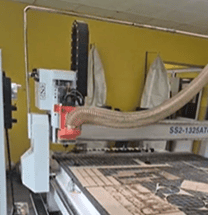
The CNC router used in our lab was designed by SYNTEC. It integrates Japanese control software, Italian motors, and a Chinese structural chassis.
The machine operates under the G-code standard and supports up to 8 different tools in a single project. It follows a 3-axis prismatic milling method, where the material remains fixed and only the tool moves.
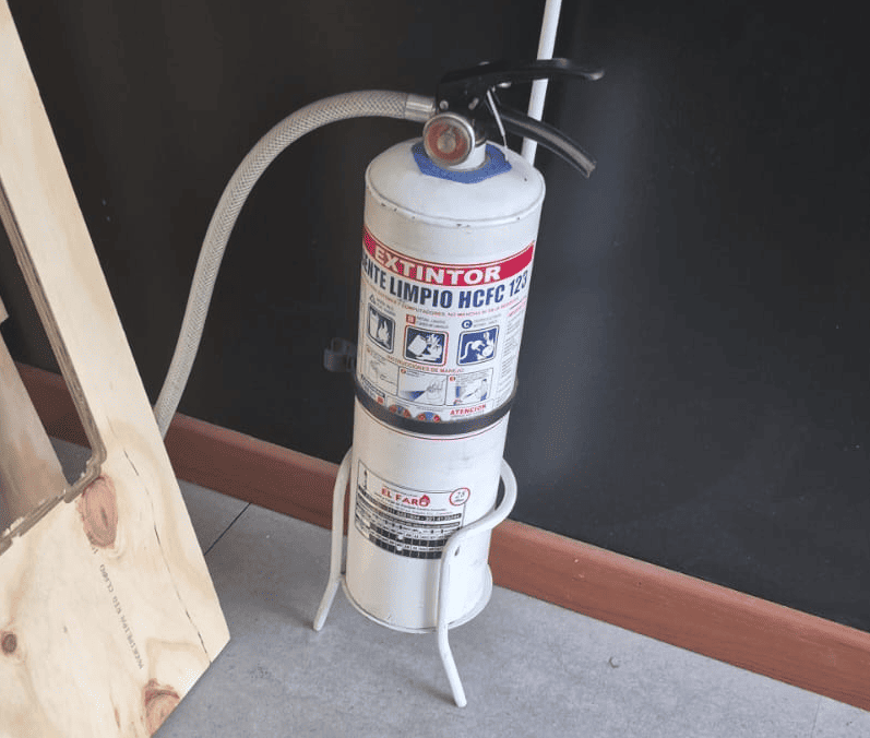
Safety Zone and Fire Protection
The machine includes a marked safety perimeter on the floor, indicating the restricted operator zone during operation.
Fire extinguishers are strategically placed both inside the machining room and at the Fab Lab entrance.
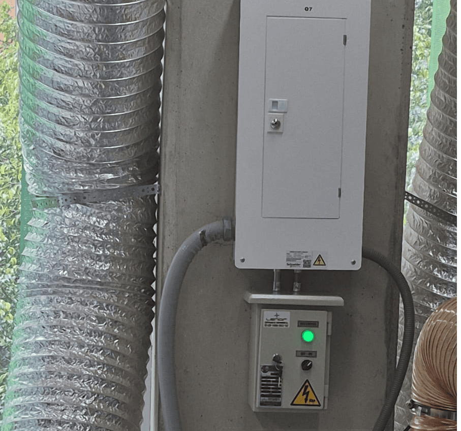
Electrical System and Power Control
The machine is connected to a regulated electrical panel that prevents overcurrent spikes and short circuits.
A master power switch controls the entire system, ensuring safe startup and shutdown procedures.
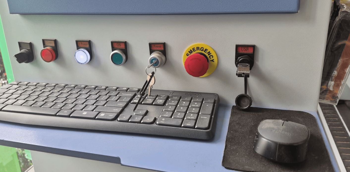
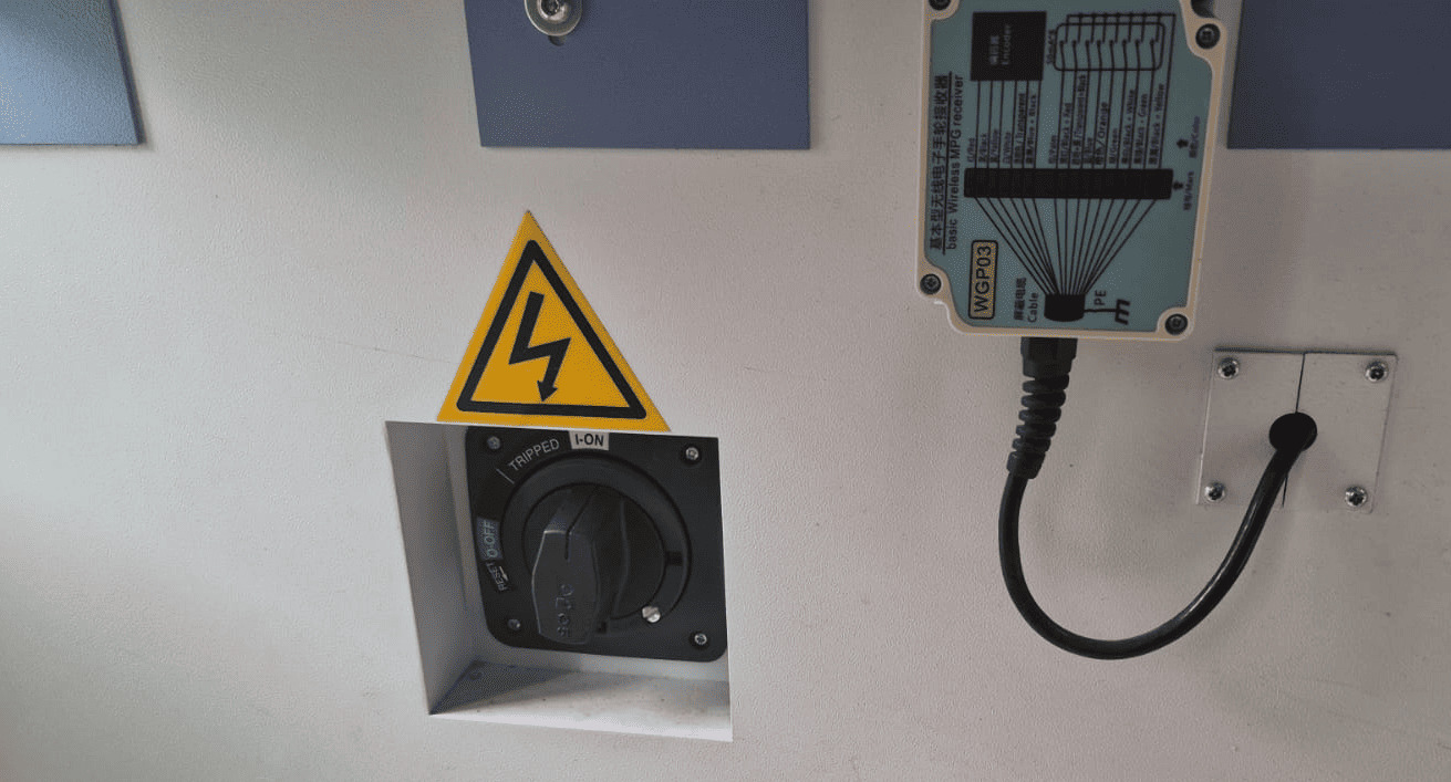
Control Panel and Emergency Systems
The control panel includes:
- Security key switch
- Phase activation switches
- Emergency stop button
- Visual alarm indicators
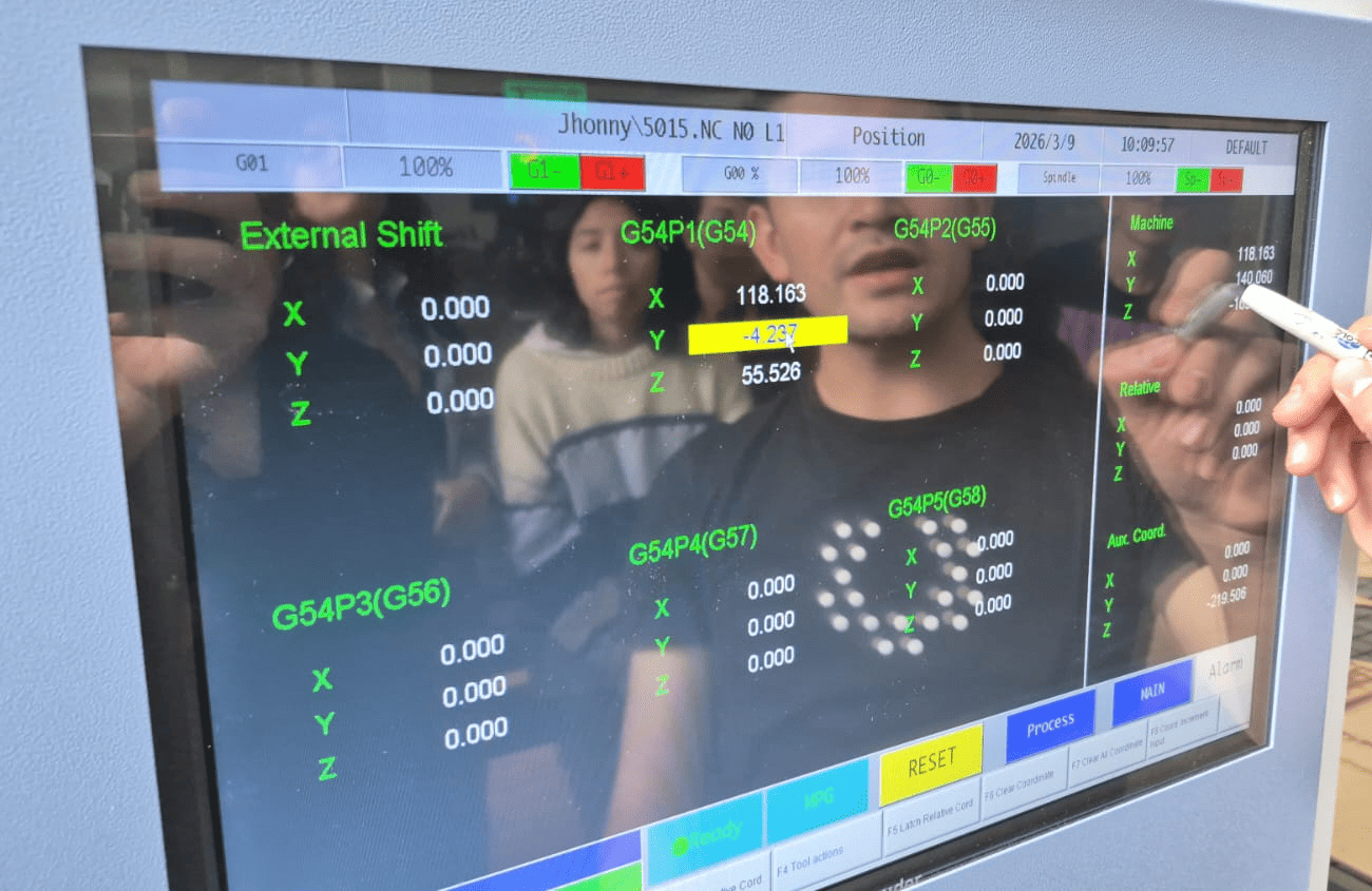
The interface allows monitoring of operational states: cutting mode, stop mode, and error alerts.
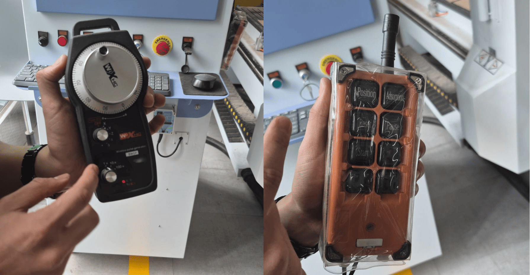
Remote Control Systems
Two remote controllers allow:
- Manual positioning of the spindle
- Work mode adjustments
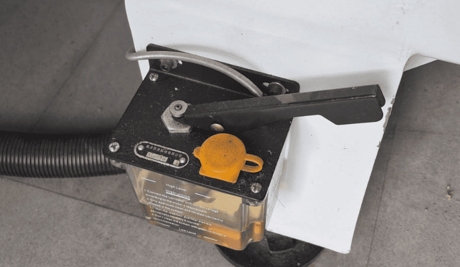
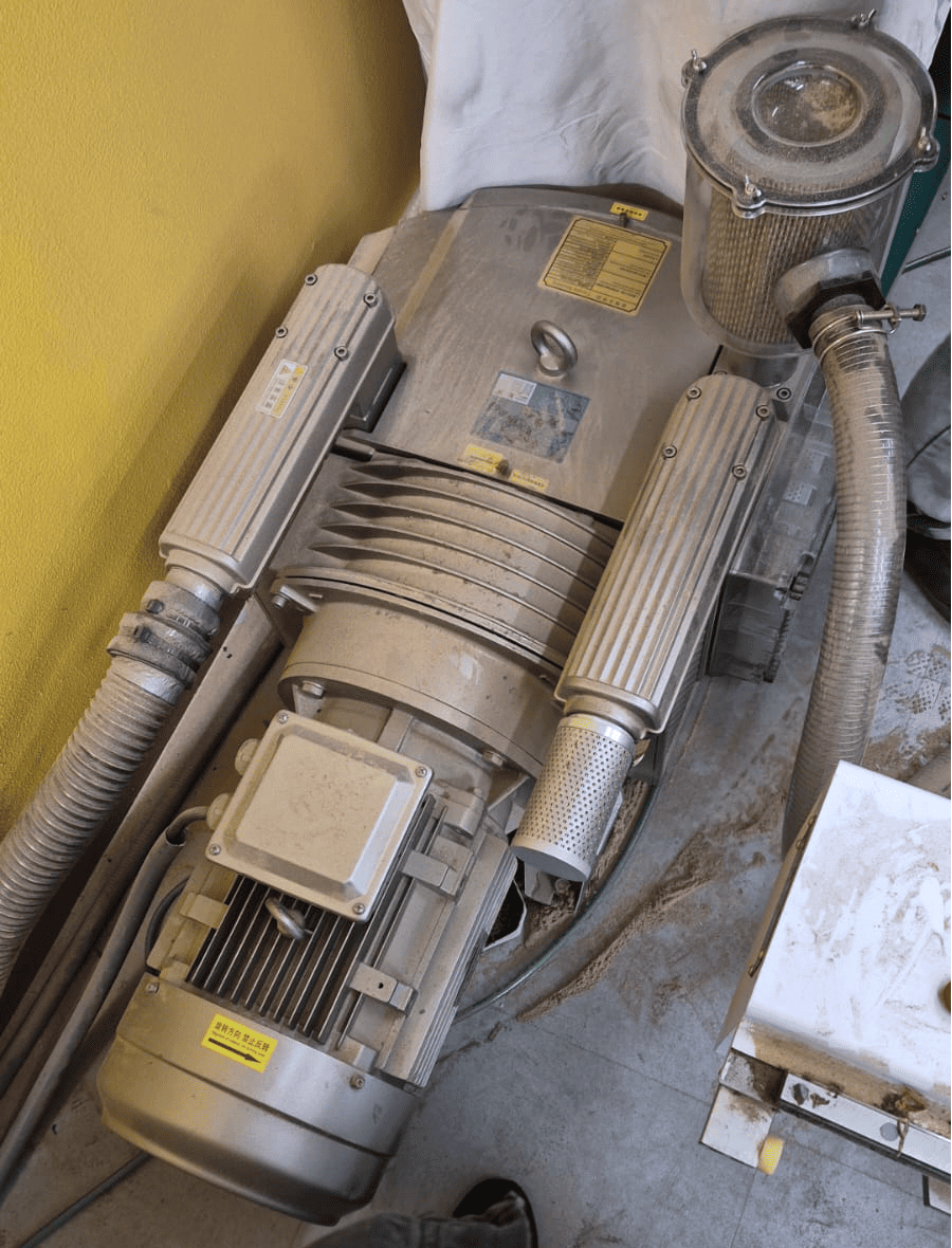
Lubrication and Air Systems
The machine includes a pedal-controlled oil pump for lubricating moving components.
An air compressor ensures proper tool and material clamping.
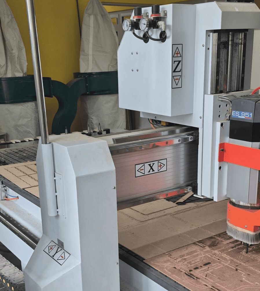
Axes, Tools and Automatic Tool Change
The CNC router operates using a 3-axis prismatic system (X, Y, Z), where the tool moves along three orthogonal directions while the material remains fixed. This configuration allows precise control of tool position and depth, which is essential for both surface engraving and full-depth cutting operations.
Each axis plays a specific role in the machining process:
- X and Y axes: define the horizontal movement of the tool across the material surface.
- Z axis: controls the cutting depth and is critical for defining tool engagement with the material.
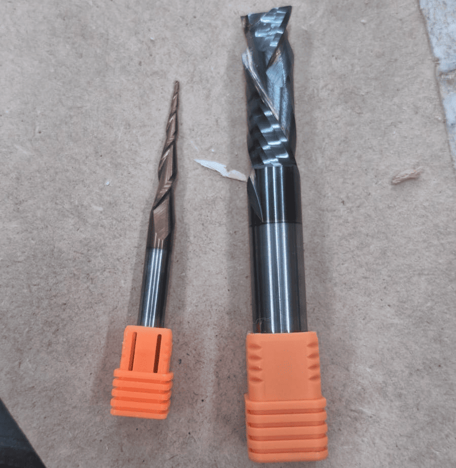
The machine supports multiple cutting tools, each designed for a specific type of operation. During this assignment, different tools were used depending on the machining stage:
- Engraving / routing tool: used for shallow cuts and detailed features.
- End mill (1/4 inch): used for contour cutting and material separation.
One of the most important features of the machine is its automatic tool change system, which allows switching between tools without manual intervention. The machine can store multiple tools in predefined positions and select them automatically according to the programmed G-code.
This system significantly improves workflow efficiency, as it enables complex machining sequences—such as engraving followed by cutting—to be executed in a single operation. It also reduces setup time and minimizes human error during tool changes.
Understanding how tool selection, tool diameter, and cutting depth interact with each axis is essential for achieving accurate results. Incorrect tool choice or improper Z calibration can lead to poor surface quality, incomplete cuts, or even tool breakage.
CNC Router in Operation
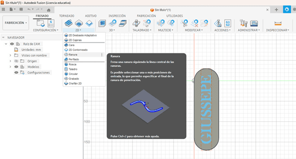
2. Test Model Processing and CAM Workflow in Fusion 360
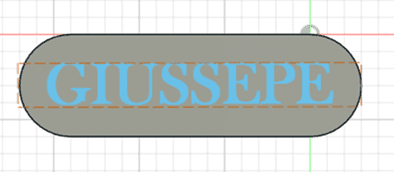
For the cutting and routing tests, a simple test model was designed in Fusion 360. The geometry consisted of a semi-oval block with engraved text on top (in this case, my name: Giussepe).
The objective was to machine the model on a 12 mm plywood sheet (triplex) to evaluate toolpath behavior and surface finish quality.
CAM Setup and Work Origin
After completing the solid model, the workflow moved to the Manufacturing (CAM) workspace.
The first step was defining the stock dimensions and establishing the work origin point. This ensures that the physical material aligns correctly with the virtual coordinate system.
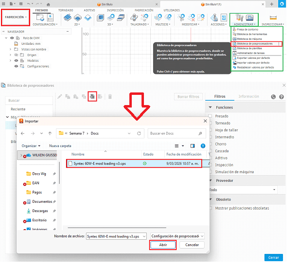
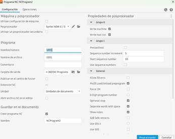
Post-Processor Selection
The appropriate post-processor was imported to ensure compatibility with the CNC controller.
Selecting the correct post-processor guarantees that the generated G-code follows the syntax required by the machine.

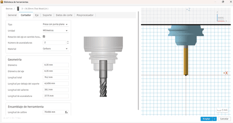
Tool Geometry Configuration
Tool parameters were configured according to the actual milling bit used.
Measurements were verified using a digital caliper, considering tool diameter, flute length, and holder dimensions.
Cutting Parameters
Cutting parameters were defined as:
- Spindle speed: 19,000 RPM
- Feed rate: 1500 mm/min
These parameters were selected to ensure stable chip formation and avoid overheating during plywood machining.
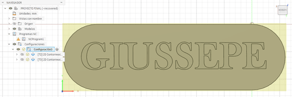
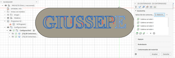
2D Contour Operation
A 2D contour operation was selected to define the outer cutting boundaries.
A ramp-style entry strategy was used, with a 2.0° inclination and a 4 mm step-down, reducing tool stress during material penetration.
Toolpath Preview
The roughing contours and cutting direction vectors were visualized before execution.
Reviewing toolpaths helps detect potential collisions or inefficient movements.
Post-Processing and G-code Generation
Once validated, the operation was post-processed, generating the final G-code file.
This file contains the machine instructions controlling spindle speed, feed rates, and tool movement across X, Y, and Z axes.
CAM Simulation
3. Machining Tests and Results – Routing and Cutting
After generating the G-code, the machining process was executed on the CNC router. The file was first imported into the machine controller software.
The material was positioned and secured using a combination of pneumatic clamps and mechanical fixtures, ensuring stability during the machining process.
The work origin (X, Y) and the ΔZ reference were defined using the machine’s automatic calibration system, guaranteeing proper alignment between the digital model and the physical material.
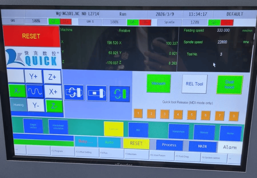
Routing Process (Engraving Phase)
Once the setup was completed, the vacuum system and dust hood were activated to ensure proper material fixation and debris removal.
The machine automatically selected the first tool and began the routing process, performing the engraving operation on the material surface.
Cutting Process (Contour Phase)
After completing the engraving phase, the CNC machine automatically changed to a 1/4 inch end mill for the contour cutting operation.
This step removed the material along the external boundaries of the geometry, separating the part from the stock while maintaining structural supports until the final stage.
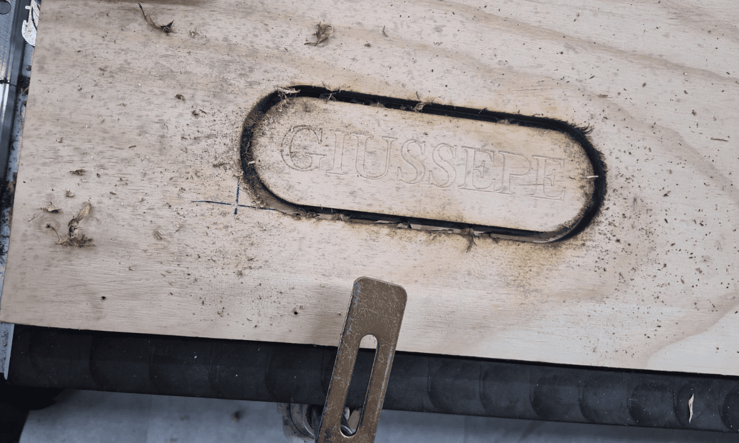
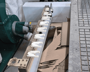
Machining Result
After the machining process, the material remained attached to the stock through small holding tabs, preventing displacement during cutting.
At this stage, the geometry was fully defined but required post-processing to remove burrs and release the final part.
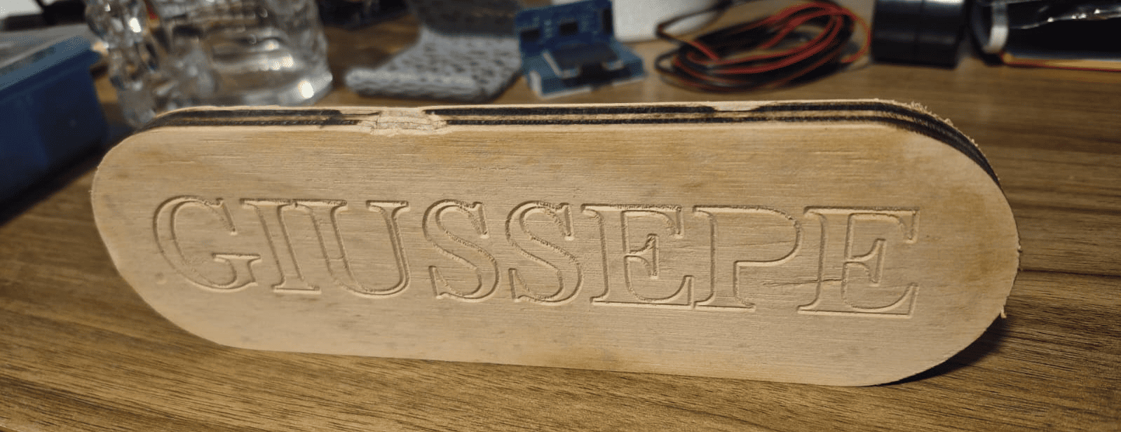
Final Result After Post-Processing
After removing the holding tabs and performing light sanding, the final part was obtained with clean edges and improved surface finish.
This step highlights the importance of post-processing in CNC workflows, as machining alone does not always produce a ready-to-use surface.
General Group Conclusion
This group assignment provided a comprehensive understanding of the full CNC machining workflow, from machine setup and safety procedures to CAM preparation and real-world fabrication.
One of the most important insights was that CNC machining is not only a digital process, but a physical system that requires careful interaction between software, machine, and material. While CAM tools allow precise definition of toolpaths, the final result depends heavily on machine calibration, workholding strategies, and correct parameter selection.
The machining tests demonstrated how factors such as tool selection, feed rate, spindle speed, and toolpath strategy directly affect cutting quality and accuracy. The use of multiple tools and automatic tool changes highlighted the importance of planning operations in the correct sequence.
Additionally, the routing and contour cutting processes showed the necessity of dividing operations into stages, ensuring that engraving and internal features are completed before releasing the final geometry from the material.
The setup phase also revealed the critical role of workholding and alignment. Proper positioning, secure clamping, and accurate definition of the work origin and Z reference are essential to avoid machining errors and ensure dimensional precision.
Another key takeaway was the importance of post-processing. Even when machining is executed correctly, additional steps such as burr removal and sanding are necessary to achieve a clean and functional result.
Overall, this assignment reinforced that successful CNC fabrication requires a holistic approach, where design, CAM strategy, machine setup, and material behavior must be considered as a single integrated workflow.
Downloads & Resources
This section provides access to the design resources and downloadable files created during the Computer-Controlled Machining assignment. The repository includes the complete CNC workflow, from parametric design and CAM preparation to machine configuration and G-code generation.
🛠️ Project Resources
The project repository contains all files required to reproduce the modular bookshelf, including CAD designs, CAM setup, CNC machine configuration, and machining programs.
- ✅ SolidWorks Parametric Design Files
- ✅ Fusion 360 CAM Project
- ✅ Syntec CNC Post Processor (.cps)
- ✅ CNC G-Code Program (.nc)
- ✅ Syntec Machine Configuration (.mch)
- ✅ CNC Tool Library & Project Assets
📁 Downloadable Files
To improve the loading performance of this documentation website, all project files have been moved to a shared Google Drive folder.
The repository contains the complete CAD models, CAM setup, Syntec post processor, CNC machining program, machine configuration files, and supporting documentation developed during this assignment.
Additional machining strategies, updated tool libraries, and future design revisions may be added as the project evolves.