Individual Assignment Requirements
- Design, document and 3D print an object (small, few cm³, limited by printer time) that could not be easily made subtractively.
- 3D scan an object and document the process (optionally print it).
- Include original design files used for 3D printing.
- Provide clear documentation of the workflow, including design decisions, printing parameters, and results.
- Include hero shots of the final printed object.
Learning Outcomes
- Identify the advantages and limitations of 3D printing.
- Apply design methods considering additive manufacturing constraints.
- Understand and operate 3D printing workflows and parameters.
- Demonstrate how 3D scanning technologies digitize physical objects.
- Evaluate when additive manufacturing is preferable over subtractive methods.
Progress Status
Summary of completed tasks for Week 05 – 3D Scanning and Printing.
Tested design rules including overhangs, bridging, tolerances and minimum feature size.
Designed a small object specifically optimized for additive manufacturing constraints.
Configured slicing parameters and successfully printed the designed object.
Digitized a physical object using 3D scanning and processed the resulting mesh.
Reflection on Printer Characterization (Group Assignment)
Based on the group assignment, I focused my analysis on the Creality Hi 3D printer with a 0.4 mm nozzle, which showed a strong balance between resolution, precision, and printing speed.
One of the most important insights was understanding how the nozzle diameter directly affects print quality and design constraints. Compared to larger nozzles (such as 0.8 mm), the 0.4 mm nozzle allows:
- Higher resolution in small details
- Better definition of text and fine geometries
- More precise tolerances and clearances
- Improved surface finish
This was clearly observed in the multicolor prints, where the surface quality, detail definition, and overall finish were significantly improved compared to larger nozzle configurations.
From the characterization tests, I also learned that printing parameters play a critical role. For example, a layer height of 0.2 mm combined with high printing speeds can affect dimensional accuracy, overhang quality, and surface finish if not properly calibrated.
Another key takeaway was the relationship between temperature and material behavior. The temperature tower test showed that:
- Low temperatures caused stringing and poor layer adhesion
- High temperatures caused slight deformation
- An optimal range (~210–215°C) provided the best balance
This reinforced that 3D printing is not only about geometry, but also about process control and material behavior.
Finally, I understood that design must adapt to the capabilities of the machine. With a 0.4 mm nozzle, it is possible to design smaller features and tighter tolerances, but parameters such as speed, cooling, and support strategy must still be considered to ensure successful prints.
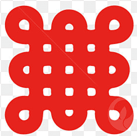
3D Design – Chinese Knot Geometry
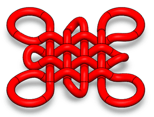
For this assignment, I selected a Chinese knot geometry as my design object. This structure is characterized by a continuous interwoven path that creates a complex pattern of loops and crossings.
The reference was based on a traditional Chinese knot pattern, which was later translated into a 3D parametric model using SolidWorks :contentReference[oaicite:0]{index=0}.
This geometry was intentionally chosen due to its high complexity and its suitability for additive manufacturing.
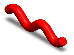
Base Geometry Definition
The design process started by creating a curved path profile, which defines the fundamental shape of the knot.
This profile acts as the building block of the entire structure, allowing the generation of smooth and continuous geometry.
Pattern Generation
Once the base profile was defined, it was replicated using a linear pattern to create a matrix of parallel elements.
This step allowed the construction of the woven structure by repeating the same parametric element.
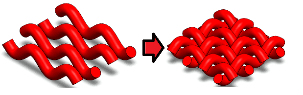
Interwoven Structure
The most critical step was defining the over-under relationships between the different segments.
This created the characteristic woven structure of the knot, requiring careful control of geometry and spatial positioning.
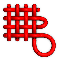
Final 3D Model
The final result is a continuous 3D geometry where all elements are interconnected, forming a single solid structure.
This type of geometry is ideal for additive manufacturing due to its complexity and continuous topology.
Modeling Process – SolidWorks
The following video shows the complete modeling process of the Chinese knot in SolidWorks, including profile creation, pattern generation, and the construction of the interwoven structure.
This process demonstrates the use of parametric modeling techniques such as sweep features, patterns, and controlled intersections to generate complex geometry.
Why This Object Cannot Be Made Subtractively
- The geometry contains interwoven elements that cannot be accessed by standard cutting tools.
- It includes internal and hidden regions that are unreachable in subtractive processes.
- The structure has undercuts and multi-directional features.
- It is a continuous topology, meaning it cannot be split into simpler machinable parts without altering its design.
Additive manufacturing allows this object to be produced layer by layer, making it possible to fabricate geometries that would otherwise be impossible using traditional subtractive methods.
3D Printing Process – Creality Hi
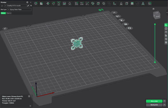
After completing the design, the model was exported as an STL file and imported into Creality Print for slicing and preparation.
This step allowed me to visualize the model within the printer workspace and begin configuring the printing parameters :contentReference[oaicite:0]{index=0}.
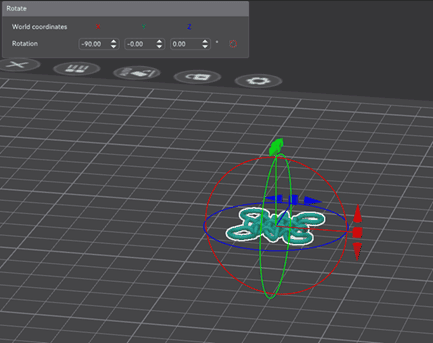
Model Orientation
One of the most important steps was adjusting the orientation of the model to minimize the use of supports.
Due to the interwoven geometry, an incorrect orientation would generate excessive supports and affect surface quality. By optimizing the orientation, I reduced material usage and improved the final finish.
Slicing and Printing Parameters
Before printing, the model was processed in the slicer software, where all manufacturing parameters were defined. This step translates the 3D model into machine instructions (G-code), determining how the printer builds the object layer by layer.
The material used was PLA (Hyper PLA), selected due to its ease of printing, low warping, and good surface finish. PLA is ideal for prototyping and detailed geometries such as the Chinese knot.
Layer and Speed Configuration
A 0.2 mm layer height was used as a balance between print speed and resolution. Lower layer heights improve detail but increase printing time.
- First layer speed: 60 mm/s (for better adhesion)
- Outer wall: 150 mm/s (surface quality)
- Inner wall: 300 mm/s (structural speed optimization)
- Top surface: 200 mm/s
Slower speeds in critical areas improve print quality, while higher speeds reduce overall printing time.
Support and Overhang Strategy
Due to the interwoven geometry, automatic supports were enabled with a threshold angle of 30°, ensuring that unsupported regions could be printed without collapsing.
Additionally, overhang speed reduction was activated to slow down printing in critical areas, improving layer adhesion and reducing defects.
Adhesion and Stability
A brim was used to improve bed adhesion and prevent the part from detaching during printing. This is especially important for small contact areas.
The skirt was also configured to prime the nozzle before printing, ensuring consistent material flow from the first layer.
Process Optimization
Features such as prime tower and controlled extrusion settings were used to stabilize material flow and maintain consistent extrusion throughout the print.
The slicing preview allowed verification of toolpaths, support distribution, and layer structure, ensuring that the geometry could be printed successfully before starting the fabrication process.
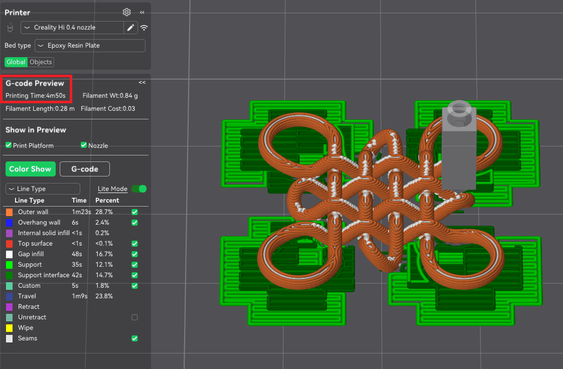
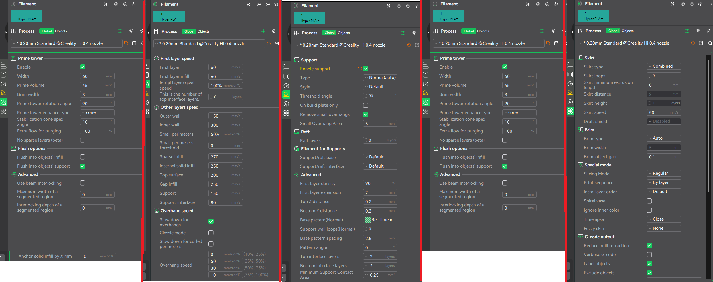
Slicing preview and detailed configuration of printing parameters.
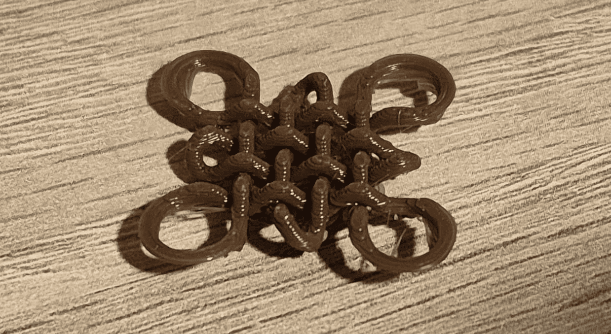
Final Printed Result
The final printed object successfully reproduced the complex geometry of the Chinese knot.
The interwoven structure was clearly visible, demonstrating that additive manufacturing can handle geometries that would be impossible to fabricate using subtractive methods.
Reflection on the Printing Process
- Orientation is critical: it directly affects support usage, surface quality, and print success.
- Complex geometries require careful slicing: especially when dealing with overhangs and intersections.
- Short prints are useful for validation: this allowed quick iteration and verification of the design.
- Additive manufacturing advantages: the knot could be printed as a single piece without assembly.
This process reinforced the importance of understanding both design and manufacturing constraints when working with 3D printing technologies.
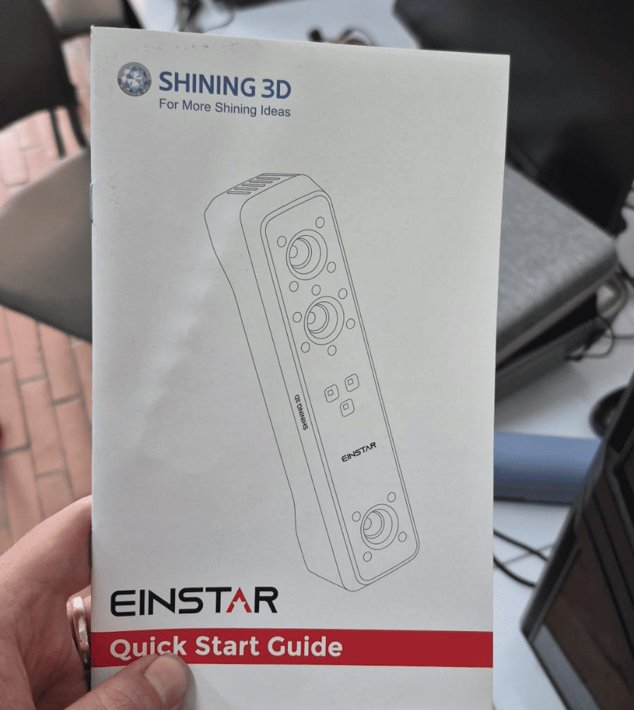
3D Scanning Process – EINSTAR Shining 3D
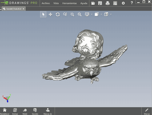
For the 3D scanning assignment, I used the EINSTAR Shining 3D scanner to digitize a physical object.
The selected object was a Funko Pop of Gandalf riding an eagle. This object was chosen due to its complex geometry and fine details, making it suitable for evaluating scanning capabilities :contentReference[oaicite:0]{index=0}.
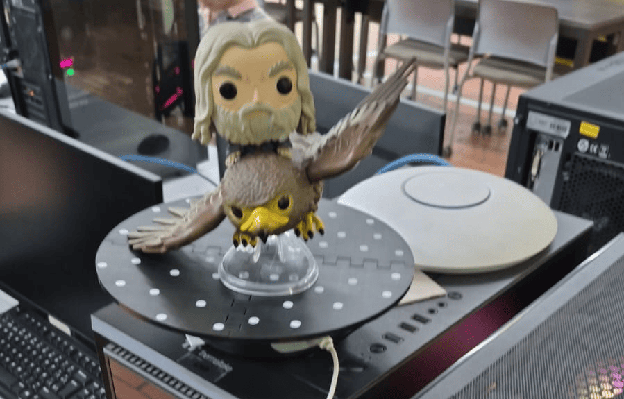
Scanning Setup
The object was placed on a rotating base with reference markers (black surface with white dots), which helps the scanner track position and orientation during the scanning process.
The rotating platform allowed continuous capture from multiple angles, improving coverage of the geometry.
Scanning Process
The following video shows the scanning process using the EINSTAR scanner, capturing multiple passes to reconstruct the full geometry of the object.
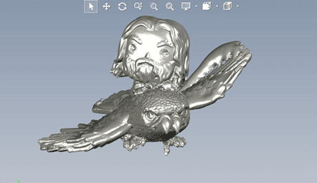
Scan Result
After processing the captured data, the result was a 3D mesh in STL format.
The model preserved most of the geometric features of the original object, including complex surfaces such as the wings and facial details.
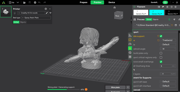
Post-processing and Preparation
The scanned model was imported into Creality Print for further processing and preparation for printing.
A cylindrical base was added to improve stability during printing and ensure proper adhesion to the build plate :contentReference[oaicite:1]{index=1}.
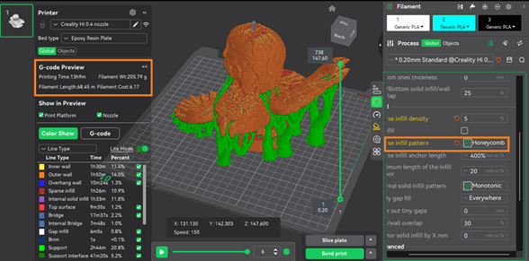
Printing Configuration
Due to the complexity of the scanned geometry, tree supports were used to properly support overhangs and delicate features such as the wings.
The slicing preview showed the support distribution and confirmed that the geometry required extensive support structures.
Final Printed Scan
The scanned model was successfully printed, preserving the overall geometry and recognizable features of the original object. The main proportions of the character and the eagle are clearly identifiable, demonstrating that the scanning workflow was able to capture the global structure of the object.
However, a deeper analysis reveals that although the global shape is accurate, surface quality and fine details are affected by reconstruction errors introduced during the scanning process.
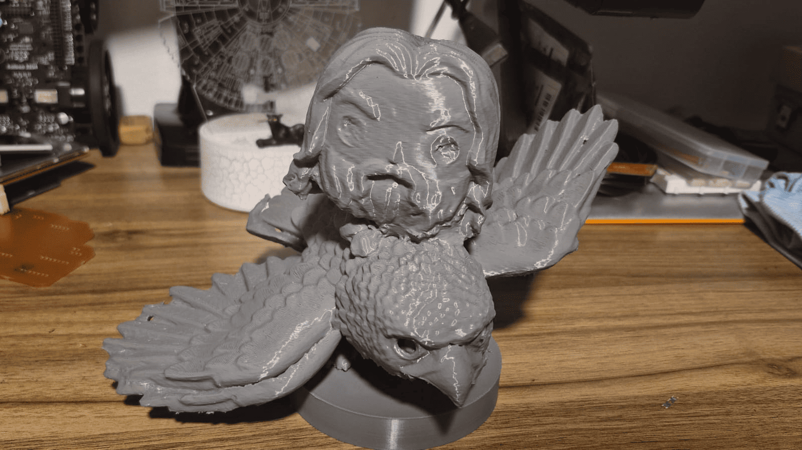
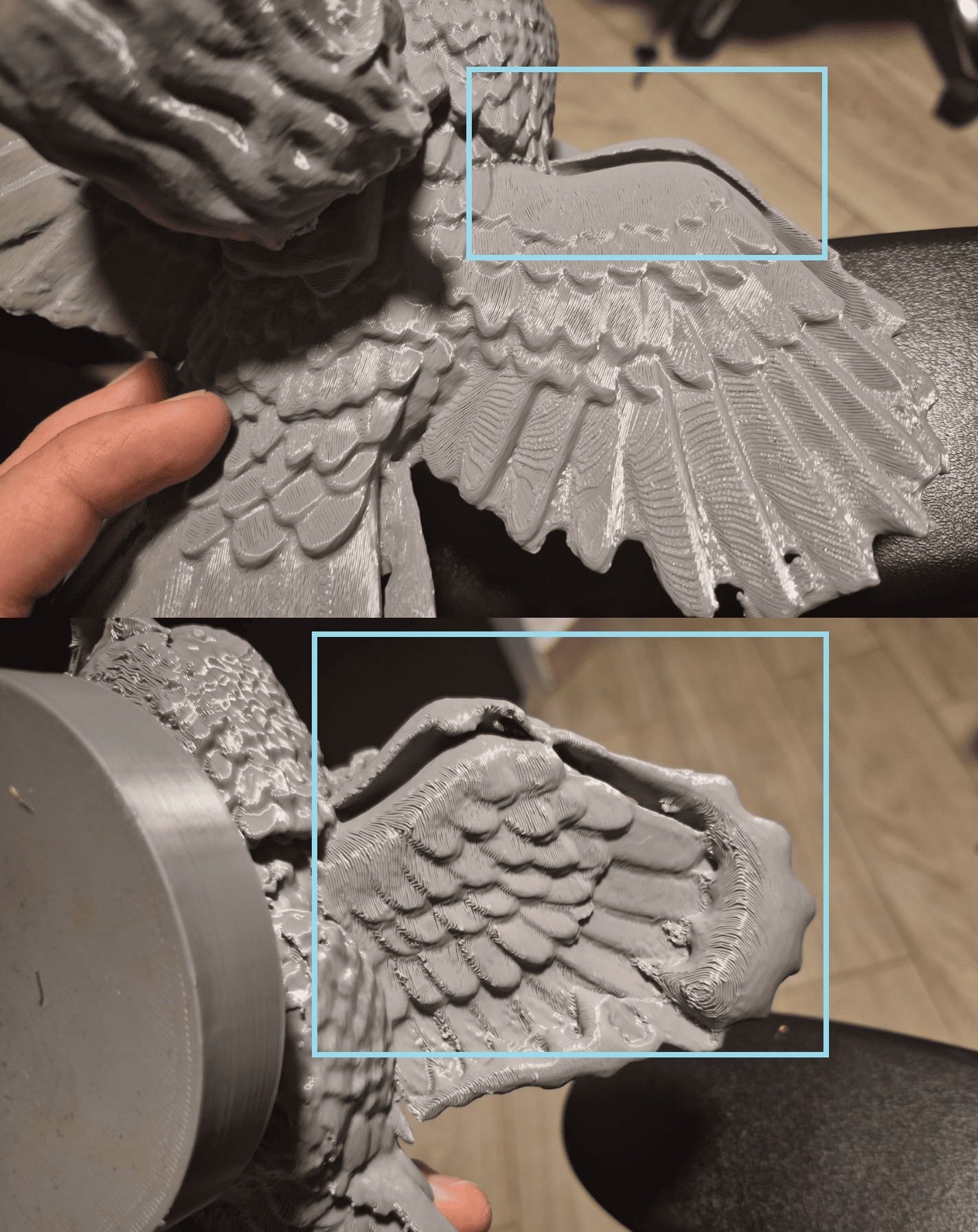
Detailed Analysis of Defects
As shown in the detailed view, several surface irregularities are present, particularly in the wings of the eagle. These defects appear as bulges, double layers, and inconsistent surface textures.
These artifacts originate from errors in the point cloud reconstruction. When multiple scanning passes are misaligned, overlapping geometry is generated, producing duplicated surfaces that later appear as thickness inconsistencies.
Additionally, holes are visible in critical areas, such as the eyes of both the rider and the eagle. These defects are typically caused by:
- Occluded regions during scanning
- Insufficient capture angles
- Low point cloud density in small features
Since these areas were not fully captured, the mesh reconstruction left missing surfaces that were not automatically repaired during post-processing.
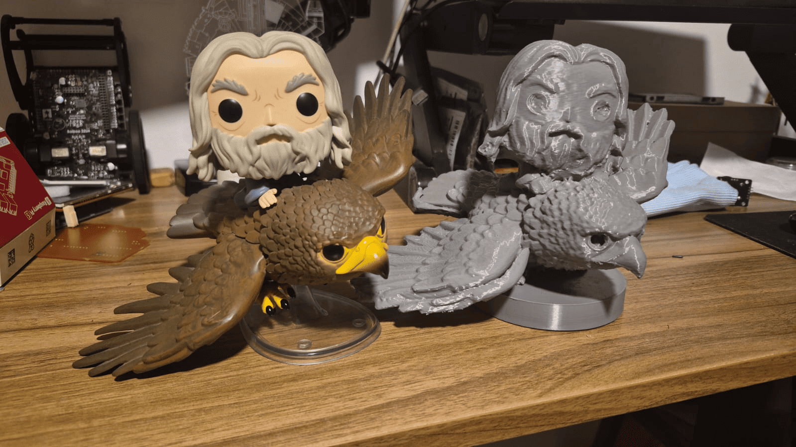
Hero Shot – Final Result Comparison
The final result is presented alongside the original Funko Pop figure, allowing a direct comparison between the scanned model and the reference object.
While the printed model successfully captures the overall form and scale, differences in surface quality and fine detail resolution are evident. The original object shows smooth and well-defined features, whereas the scanned model presents noise, layer artifacts, and minor geometric distortions.
This comparison highlights a key insight: the quality of a 3D print based on scanning is directly dependent on the accuracy of the data acquisition stage. Proper scanning strategy and mesh cleanup are essential to achieve high fidelity results.
Challenges and Errors
Scanning Errors
During the first scanning attempt, multiple passes were performed over the same region of the object. This caused the scanner to lose tracking and spatial reference.
As a result, the point cloud became misaligned, generating duplicated and distorted geometry in the final mesh.
- Duplicated features (eagle with two beaks)
- Deformation in the left wing
- Incorrect alignment of point cloud data
- Noise and overlapping geometry
Technical Analysis
This issue is directly related to how structured-light scanners track geometry. The scanner relies on continuous spatial references (markers and geometry features) to maintain alignment between frames.
When too many passes are made over the same area without proper progression, the system may incorrectly interpret the position, causing a shift in the reconstructed mesh.
Additionally, dark surfaces and complex geometries (such as the wings and small details) can reduce tracking reliability, increasing the probability of alignment errors.
Correction Process
To fix the issue, a manual mesh cleaning process was required.
- Removal of duplicated and overlapping geometry
- Cleaning of noisy regions in the mesh
- Correction of distorted areas
- Reconstruction of missing or damaged surfaces
This process required careful inspection of the model to ensure that the corrected geometry matched the original object.
Lessons Learned
- Controlled and progressive scanning is essential to maintain tracking stability.
- Avoid scanning the same area repeatedly without changing perspective.
- Complex geometries require multiple angles, but with structured movement.
- Post-processing is a critical step in converting raw scan data into usable models.
This experience demonstrated that 3D scanning is not only about capturing data, but also about understanding the limitations of the technology and applying proper strategies during acquisition and processing.
General Reflection
This week provided a comprehensive understanding of the relationship between design, fabrication, and digital reconstruction through 3D printing and scanning technologies.
One of the most important insights was realizing that additive manufacturing is not only a fabrication method, but a design paradigm. The Chinese knot project demonstrated how complex geometries—such as interwoven structures and continuous paths—can be designed specifically to take advantage of layer-by-layer fabrication, something that would be extremely difficult or impossible using subtractive processes.
Through the printer characterization and the use of the Creality Hi with a 0.4 mm nozzle, I understood how machine parameters directly influence design decisions. Factors such as resolution, tolerances, overhang limitations, and print orientation became essential constraints that guided the modeling process.
The printing phase reinforced the importance of slicing strategy and process control. Adjusting orientation to reduce supports, analyzing toolpaths, and validating prints through quick iterations showed that successful fabrication depends as much on preparation as on the design itself.
The 3D scanning process introduced a different perspective: instead of creating geometry, the challenge was to capture and reconstruct reality. This highlighted limitations related to tracking, surface properties, and data alignment. The scanning errors—such as duplicated geometry and distortions—demonstrated that raw data is often imperfect and requires careful post-processing to become usable.
A key takeaway from this week is that both technologies—printing and scanning—are deeply interconnected. While 3D printing transforms digital models into physical objects, 3D scanning enables the reverse process, bridging the gap between the physical and digital worlds.
Overall, this week strengthened my understanding of how to design for manufacturing, how to adapt to machine constraints, and how to critically evaluate both the capabilities and limitations of digital fabrication tools.
Downloads & Resources
This section provides access to the design resources and downloadable files created during the 3D Scanning and Printing assignment. The project includes CAD models, additive manufacturing files, slicing configurations, and scanned objects generated throughout the complete digital fabrication workflow.
🛠️ Project Resources
The resources developed during this assignment cover the complete workflow from 3D design to fabrication and reverse engineering through 3D scanning.
- ✅ SolidWorks CAD Model
- ✅ STL File for 3D Printing
- ✅ 3MF Slicer Configuration
- ✅ 3D Scanned Object (STL)
- ✅ Manufacturing & Documentation Files
📁 Downloadable Files
To improve the loading performance of this documentation website, all project files have been moved to a shared Google Drive folder.
The repository contains the original SolidWorks model, STL files, 3MF printing configuration, scanned object, and supporting documentation developed during the assignment.
Additional versions, optimized print profiles, and updated documentation may be added as the project evolves.