Group Assignment Requirements
- Complete lab safety training.
- Characterize the laser cutter’s focus, power, speed, kerf, joint clearance, and engraving parameters.
- Document the group work and reflect on the learning outcomes.
Learning Outcomes
- Understand and apply lab safety protocols.
- Calibrate laser focus and evaluate cutting parameters.
- Experimentally determine optimal speed and power settings.
- Measure and define kerf compensation values.
- Evaluate engraving performance on different materials.
Progress Status
Summary of completed tasks for Week 03 – Group Assignment.
Machine safety procedures, electrical system, and air extraction protocols documented.
Z-axis calibration and experimental speed/power characterization.
Joint clearance testing and definition of -0.15 mm compensation.
Comparative engraving analysis on MDF and acrylic materials.
1. Safety Training
The laser cutter is installed inside a clearly marked safety zone defined by yellow and black floor markings. The operator must remain within this area during machine operation. The electrical system includes a dedicated high-power control panel, a safety breaker, and an emergency stop button. Air quality is managed through a dual extraction system consisting of a ceiling-mounted extractor and a secondary extractor directly connected to the laser cutter. Extracted air is filtered and redirected through a particulate retention system. All systems are maintained under periodic preventive maintenance protocols established by the Fab Lab.
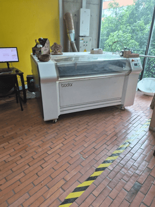
Work Area Control
Laser cutting area delimited by floor safety markings.
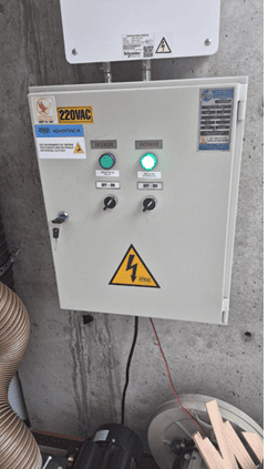
Electrical Control Panel
Main electrical panel powering the laser cutter and extractors.
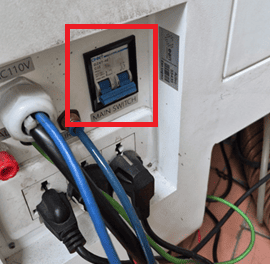
Safety Breaker
Dedicated electrical breaker for emergency power isolation.
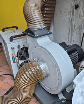
Air Extraction Pump
Extraction system connected directly to the laser cutter.
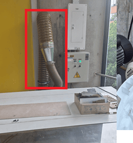
Air Filtration System
Filtration and particulate redirection system.
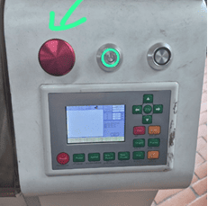
Control Interface
Control panel including emergency stop and power controls.
Image files: S1Img1.png – S1Img6.png
2. Characterize your Lasercutter — Focus, Power and Speed
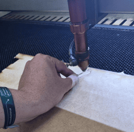
Step 1 — Z-Axis Focus Calibration
The laser focus was calibrated by adjusting the Z-axis to a working distance of 5 mm from the material surface. A custom-cut acrylic guide was used to ensure consistent and repeatable positioning.
Proper focus calibration is critical to achieve maximum energy concentration at the cutting point, improving edge quality and cutting efficiency.
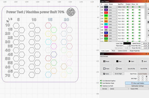
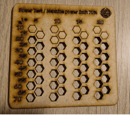
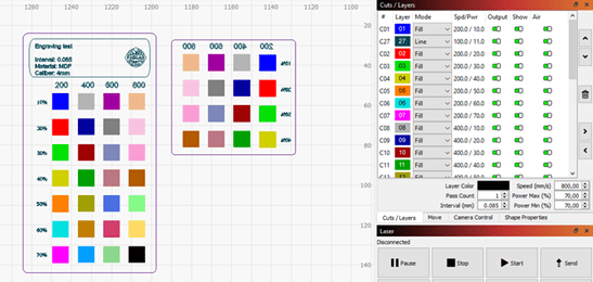
Step 2 — Speed and Power Matrix Testing
A test matrix was created in LightBurn using color-coded layers to vary cutting speed and power parameters. Each color represented a different speed and power combination.
Due to Fab Lab safety protocols, the machine is limited to a maximum of 70% of nominal power. Therefore, all tests were conducted within this safe operational range.
Step 3 — Experimental Results
After evaluating the cutting samples, the cleanest and most consistent cut on 4 mm MDF was achieved at a speed of 10 mm/s with a power range between 30% and 35%.
These parameters produced complete material penetration with minimal burning and smooth edge finishing, making them ideal baseline settings for MDF cutting using the Boodor W6 130W CO₂ laser.
3. Kerf Characterization
Kerf refers to the material removed by the laser beam during cutting. Since the laser has a finite beam diameter, the actual cut width is slightly larger than the design geometry. This material loss directly affects joint tolerances and press-fit assemblies.
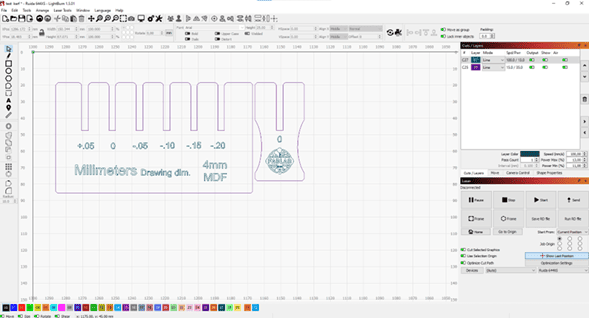
To quantify this effect, a kerf calibration pattern was prepared in LightBurn, including incremental slot variations ranging from +0.05 mm to -0.20 mm. Each variation was designed to evaluate how different tolerances influence mechanical fit when assembling interlocking components made from 4 mm MDF.
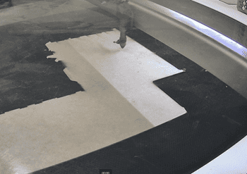
The test was performed using leftover MDF material available at the Fab Lab node of EAN University. Although the material was not new stock, it provided realistic fabrication conditions representative of typical use. Care was taken to properly align the sheet on the laser bed to ensure consistent cutting performance.
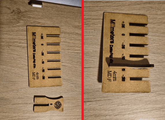
After cutting and manually assembling the test samples, each tolerance level was evaluated based on insertion force, friction stability, and structural rigidity. Larger tolerances resulted in loose joints, while smaller tolerances required excessive force and risked material damage.
The optimal mechanical performance was achieved at a kerf compensation value of -0.15 mm. This adjustment produced a firm press-fit: components could be assembled without tools, remained stable under handling, and did not cause edge deformation.
Based on these results, -0.15 mm was defined as the baseline kerf compensation value for future press-fit designs fabricated on the Boodor W6 130W CO₂ laser cutter at this Fab Lab.
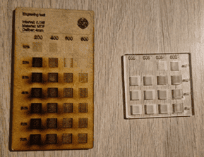
4. Engraving Tests — MDF & Acrylic
In addition to cutting characterization, engraving tests were performed on both 4 mm MDF and acrylic in order to evaluate surface quality, depth consistency, and visual contrast.
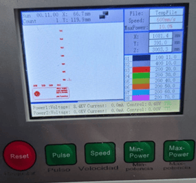
The engraving parameters were configured in LightBurn using different combinations of power and speed values. These settings were also verified directly from the machine control panel to ensure consistency between software configuration and machine execution.
For MDF, the most consistent engraving quality was achieved within a power range of 20% to 40% and speeds between 400 mm/s and 600 mm/s. Lower power values produced shallow markings, while higher power levels caused excessive burning and darkening of the surface.
In contrast, acrylic demonstrated superior engraving clarity at lower power levels. Optimal results were obtained between 20% and 30% power with speeds ranging from 600 mm/s to 800 mm/s. These settings produced clean, frosted engraving with minimal thermal distortion.
The comparison indicates that acrylic responds more efficiently to laser engraving due to its homogeneous composition and predictable thermal behavior. MDF, being a fibrous composite material, requires more energy control to prevent surface degradation.
Based on these tests, acrylic is considered a more suitable material for high-precision engraving applications, while MDF remains adequate for structural or decorative marking where surface uniformity is less critical.
Personal Conclusions
Participating in the laser cutter characterization process allowed me to better understand the relationship between digital parameters and physical outcomes. Adjusting focus, speed, power, and kerf values demonstrated how small numerical changes can significantly impact material behavior and fabrication quality.
One of the most important insights was recognizing that laser settings are not universal; they depend strongly on material composition. MDF, being a fibrous composite, reacts differently to thermal energy compared to acrylic, which has a more homogeneous structure. This directly influences engraving contrast, cutting efficiency, and dimensional accuracy.
The kerf characterization reinforced the importance of tolerance calibration in press-fit design. Defining a baseline compensation value of -0.15 mm provides a reliable reference for future projects fabricated on this machine.
Beyond technical parameters, this assignment strengthened my understanding of machine safety protocols and operational discipline. Knowing how the electrical system, extraction system, and emergency controls function increases confidence and reduces fabrication risks.
Overall, this experience shifted my perspective from simply “using a laser cutter” to understanding it as a calibrated manufacturing tool whose performance must be characterized, measured, and optimized.
Downloads & Resources
This section provides access to the design resources and downloadable files created during the Computer-Controlled Cutting assignment. The project includes parametric CAD models, laser cutting files, and LightBurn projects used throughout the fabrication workflow.
🛠️ Project Resources
This assignment was developed using parametric CAD software and laser cutting preparation tools. The project resources include design models, manufacturing files, and machine configuration projects used to validate the fabrication process.
- ✅ Parametric CAD Models (SolidWorks)
- ✅ DXF Files for Laser Cutting
- ✅ LightBurn Engraving Projects
- ✅ Kerf Calibration Tests
- ✅ Power & Speed Test Files
📁 Downloadable Files
To improve the loading performance of this documentation website, all project files have been moved to a shared Google Drive folder.
The repository contains the complete SolidWorks project, DXF files, LightBurn projects, laser cutting test files, and additional resources required to reproduce the fabrication workflow.
Updated versions and additional documentation may be added as the project continues to evolve.