Individual Assignment Requirements
- Browse through the datasheet of a microcontroller and document key architectural features.
- Write and test a program for an embedded system using a microcontroller.
- Implement interaction with local input and/or output devices.
- Demonstrate communication using wired or wireless protocols.
Learning Outcomes
- Implement programming protocols.
- Interpret and apply information from a microcontroller datasheet.
- Program a board to interact with input/output devices.
- Structure embedded software using logical architecture.
- Include source code and document the development process.
Progress Status
Summary of completed tasks for Week 04 – Embedded Programming.
Explored ESP32-C3 architecture, ADC characteristics, peripherals, and RISC-V core structure.
Implemented digital I/O testing and 12-bit analog input processing with signal scaling and analysis.
Integrated 128x64 OLED display via I2C and implemented structured frame rendering.
Developed a joystick-controlled Pong game using finite state machine architecture and hardware interrupts.
1. Exploring the Microcontroller – XIAO ESP32-C3
Board Selection and Documentation Review
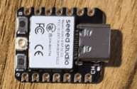
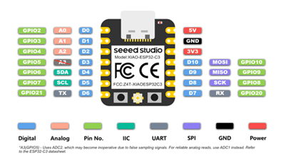
For this assignment, I decided to work with the Seeed Studio XIAO ESP32-C3, a compact development board based on the ESP32-C3 microcontroller.
Before starting the programming phase, I explored both the official documentation and the ESP32-C3 datasheet in order to understand the internal architecture and hardware capabilities of the system.
The official Seeed Studio Getting Started guide was especially helpful:
Seeed Studio XIAO ESP32-C3 Getting Started
This guide allowed me to:
- Install board support in Arduino IDE
- Configure USB communication correctly
- Understand pin mapping
- Identify ADC-capable pins
- Verify I2C and GPIO functionality
Core Architecture and ADC Capabilities
In addition to the board documentation, I reviewed the official
ESP32-C3 datasheet provided by Espressif:
ESP32-C3 Datasheet
The ESP32-C3 is based on a 32-bit RISC-V single-core processor, which differs significantly from the classic ESP32 (WROOM), built on a dual-core Xtensa architecture.
Key characteristics of the ESP32-C3 include:
- 32-bit RISC-V CPU (up to 160 MHz)
- 12-bit SAR ADC
- WiFi 802.11 b/g/n (2.4 GHz)
- Hardware cryptographic acceleration
- Multiple communication peripherals (I2C, SPI, UART)
- GPIO interrupt capability
- Native USB support (on boards like XIAO)
From the datasheet, I confirmed that the ADC resolution is 12 bits, meaning it provides 4096 discrete levels (0–4095). It also supports configurable attenuation and multiple ADC channels multiplexed to GPIO.
This was especially important because my project relied heavily on analog input (joystick control). Understanding the ADC resolution and input range allowed me to correctly scale and interpret signals.
Board Comparison and Design Decisions
It was also important to understand the difference between the ESP32 microcontroller family and the XIAO ESP32-C3 development board.
The classic ESP32 (e.g., ESP32-WROOM-32) features:
- Dual-core Xtensa architecture
- More available GPIO pins
- Larger board form factor
- Designed for feature-rich IoT systems
In contrast, the XIAO ESP32-C3 provides:
- Single-core RISC-V architecture
- Ultra-compact footprint
- Limited GPIO count
- Native USB programming
- Optimized for space-constrained embedded systems
These differences influenced my design decisions:
- I had fewer pins available.
- I had to carefully select ADC-capable pins.
- I relied on I2C to minimize GPIO usage for the display.
Reading the datasheet also clarified several key aspects:
- The real ADC resolution (12-bit, not 10-bit like classic Arduino).
- The importance of using signed integers for motion physics.
- The availability of hardware interrupts.
- The internal structure of the RISC-V core.
Instead of treating the board as a “black box,” I developed an understanding of the hardware capabilities that ultimately made the Pong game implementation possible.
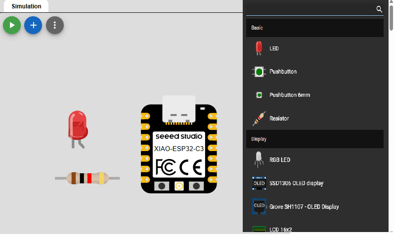
2. Simulation Workflow – Wokwi Platform
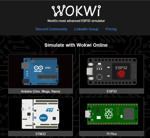
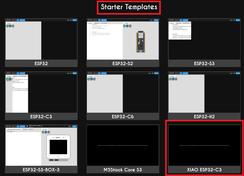
Before working with physical hardware, I used Wokwi, an online simulation platform that allows building and testing embedded systems directly in the browser.
Wokwi simulates both the microcontroller behavior and electronic components, enabling developers to write code, connect virtual circuits, and observe results in real time without requiring physical devices.
This approach is especially useful during early development stages, where errors in wiring or code could damage real hardware or slow down the debugging process.
Selecting the Embedded System
The first step is selecting the microcontroller that will act as the central processing unit of the system.
In Wokwi, this is done by choosing a predefined board (such as Arduino or ESP32). For this project, I selected a configuration equivalent to the ESP32 architecture, ensuring compatibility with the XIAO ESP32-C3 used in the real implementation.
Adding Components and Wiring
Wokwi provides a library of electronic components such as LEDs, resistors, sensors, and displays, which can be added visually to the workspace.
Each component can be connected using virtual wires, replicating the same process used in real breadboard prototyping.
This allows validating pin connections, power distribution, and communication buses (such as I2C) before assembling the circuit physically.
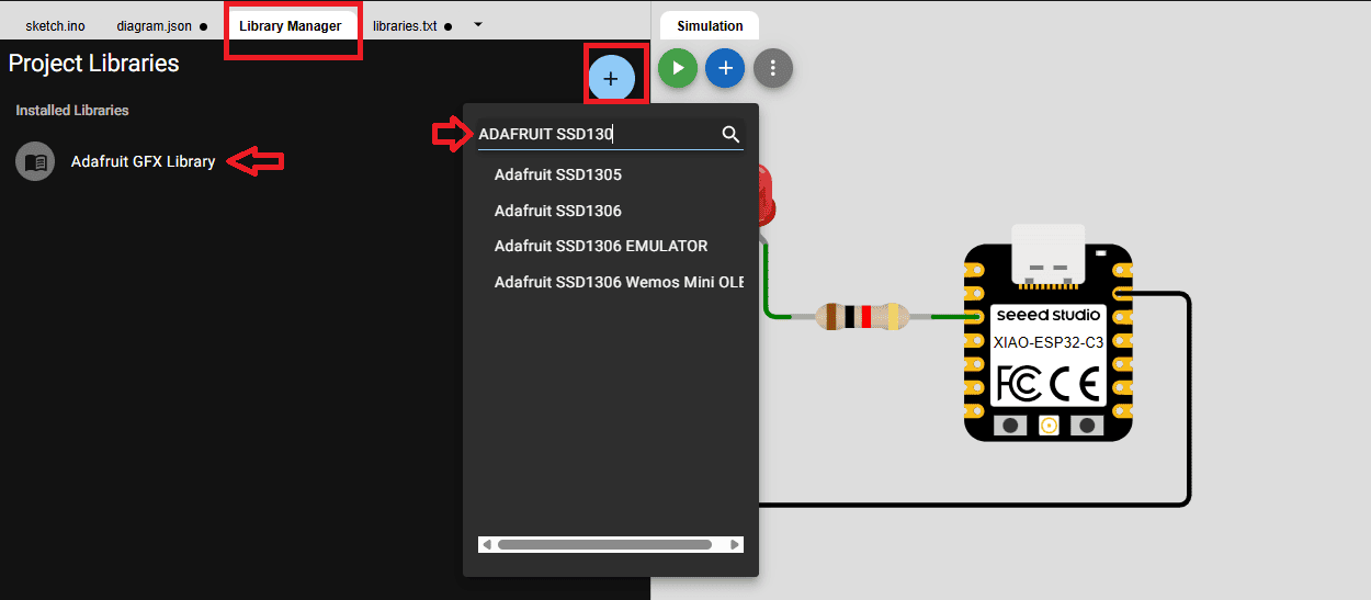
Library Integration
Similar to real embedded development, external libraries can be included to control specific hardware components.
In this project, I used:
- Adafruit GFX: for graphics rendering
- Adafruit SSD1306: for OLED display control
These libraries abstract low-level communication details, allowing faster implementation of complex functionalities such as text and graphical interfaces.
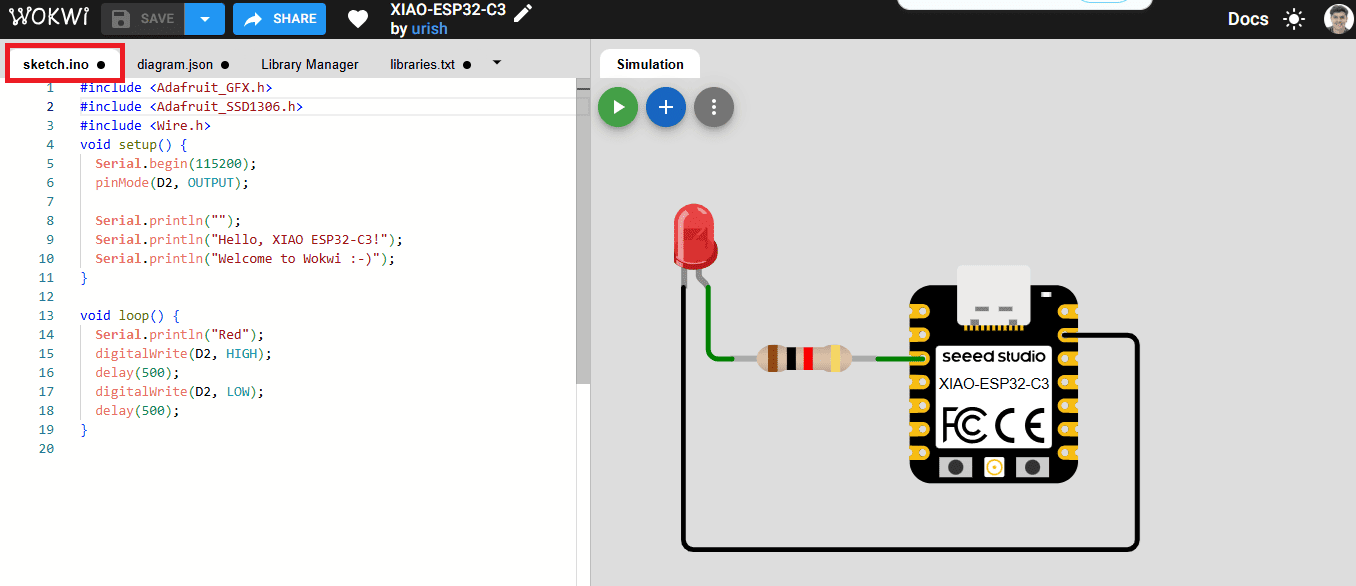
Code Development
The program is written directly in the integrated code editor, using standard Arduino-style C/C++.
The code interacts with the virtual hardware exactly as it would in a real system,
using functions such as pinMode(), analogRead(), and
library-based display functions.
This creates a realistic development environment where logic, timing, and communication protocols can be tested before deployment.
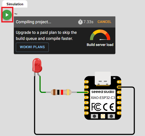
Simulation and Debugging
Once the system is configured, the simulation can be executed in real time.
During simulation, the user can observe how inputs affect outputs, verify display behavior, and analyze system responses without physical risks.
This makes Wokwi a powerful tool for debugging, as errors in logic or wiring can be identified and corrected before working with actual hardware.
Reflection on Simulation Workflow
Using Wokwi significantly improved the development workflow by enabling rapid prototyping and safe testing.
It reduced debugging time, prevented hardware damage, and allowed me to better understand system behavior before implementing the circuit physically. This demonstrates how simulation tools can bridge the gap between conceptual design and real-world embedded systems.
First Experiments – Understanding GPIO and Basic I/O
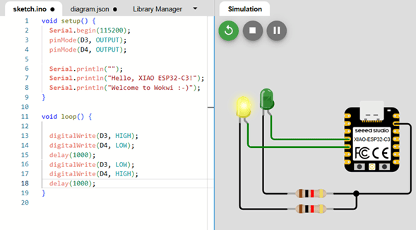
Digital Output Test – Alternating LEDs
Before moving to analog input and display communication, I started with fundamental digital input/output tests. Even though blinking LEDs may seem simple, this step is essential when working with a new microcontroller.
This basic experiment allowed me to verify:
- Pin mapping correctness
- Board configuration in Arduino IDE
- Upload process and USB communication
- Toolchain functionality
- Power stability
I connected two LEDs to digital pins and programmed them to turn on
alternately every second. During this process, I discovered an important
detail about the XIAO ESP32-C3: unlike classic Arduino boards, digital
pins must be referenced using the D prefix
(e.g., D3, D4).
Initially, I attempted to define pins using only numeric values, and the LEDs did not behave as expected. After reviewing the board documentation and checking the pin mapping, I declared:
#define LED1 D3
#define LED2 D4
Once properly defined, the alternating LED pattern worked correctly. This small issue reinforced how board abstraction layers differ between microcontroller architectures.
Demonstration Video
The following video demonstrates the alternating LED behavior, confirming correct GPIO configuration and board setup.
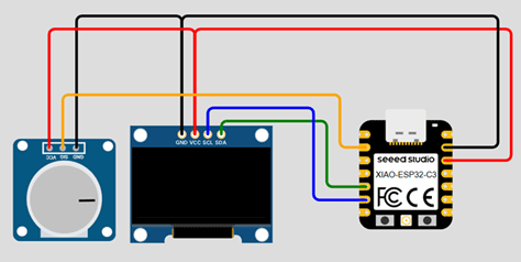
Analog Input, I2C Communication and Signal Analysis
After validating digital GPIO functionality, I moved to analog input and display communication. The objective of this phase was to:
- Read a potentiometer using the ESP32-C3 ADC
- Display the value on an OLED screen
- Analyze signal behavior using the Serial Plotter
This step allowed me to integrate multiple subsystems:
- ADC (Analog-to-Digital Converter)
- I2C communication
- Serial communication for debugging
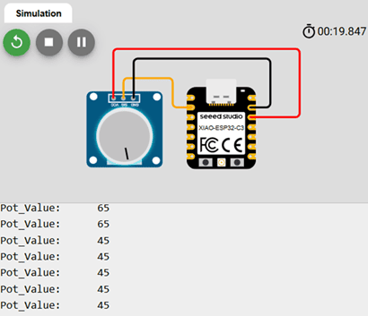
Understanding the ADC in the ESP32-C3
From the ESP32-C3 datasheet, I confirmed that the ADC resolution is 12 bits. This means:
212 = 4096 discrete levels
Therefore, the theoretical range of values is: 0 – 4095.
This differs from classic Arduino boards (such as the Uno), which use 10-bit ADC resolution (0–1023). Understanding this difference was critical when scaling and mapping values.
When I first tested analogRead(), I verified that
readings indeed fell within the expected 12-bit range.
Resolution vs Precision
At this stage, I reflected on an important concept: resolution does not equal precision.
Even though the ADC provides 4096 discrete levels, effective precision depends on:
- Electrical noise
- Power stability
- Signal source impedance
- Internal ADC characteristics
By keeping the potentiometer at a fixed position, I observed small fluctuations in readings. This demonstrated real-world analog noise and reinforced that embedded signals are never perfectly stable.
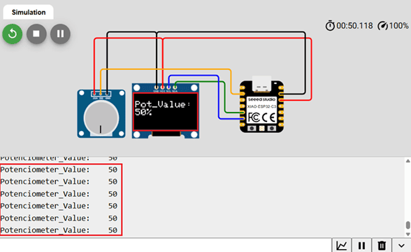
Mapping and Scaling the ADC Values
Since the OLED display space is limited and the application did not require full 12-bit precision, I scaled the ADC range (0–4095) into a smaller, meaningful range (0–100).
potValue = analogRead(POT);
potValue = map(potValue, 0, 4095, 0, 100);
This allowed me to:
- Represent the potentiometer value as a percentage
- Simplify on-screen visualization
- Reduce unnecessary resolution for human interpretation
This reinforced an important embedded design principle: the useful resolution of a signal depends on the application context, not only on hardware capability.
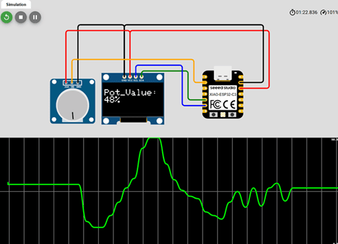
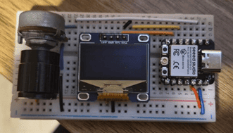
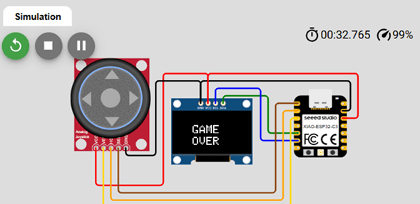
Implementing the OLED Display (I2C)
To visualize the analog value, I connected a 128x64 OLED display using I2C communication.
I chose I2C because:
- It uses only two lines (SDA and SCL)
- It conserves GPIO pins
- It is ideal for compact boards like the XIAO
Using the Adafruit SSD1306 library, I initialized the display, cleared the buffer, printed the scaled value, and updated the screen. The communication worked reliably after confirming the I2C address (0x3C).
Physical Implementation Demonstration
The following video shows the full physical implementation, including potentiometer input, OLED visualization, and real-time serial monitoring.
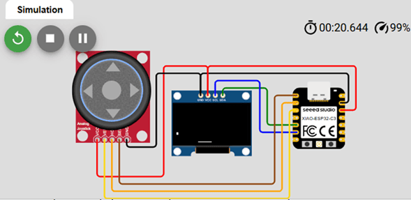
From Signal Processing to Game Logic – Designing the Pong System
After validating analog input and OLED output independently, I moved to the main objective of this assignment: building an interactive embedded game using a joystick and a display.
Instead of directly mapping the joystick value to a screen position, I began thinking about control logic, system architecture, and physics modeling. This section marks the transition from simple I/O testing to structured embedded system design.
From Analog Mapping to Control Strategy
position = map(analogValue, 0, 4095, 0, 127);
During testing, I observed small ADC fluctuations even when the joystick was centered. A direct linear mapping caused constant paddle jitter.
Instead of aggressive filtering, I implemented a threshold-based control system with a dead zone:
- If joystick value > upper threshold → move right
- If joystick value < lower threshold → move left
- If value remains within dead zone → no movement
This converted a continuous analog signal into discrete directional control, which is more appropriate for game interaction.
Designing the Game Loop
I structured the program into three conceptual phases:
- Read inputs
- Update game state (physics)
- Render frame
Inside the PLAYING state, the logic sequence became:
- Read joystick
- Update paddle position
- Update ball position
- Detect collisions
- Render full frame
- Update display buffer
Separating physics and rendering eliminated unstable behavior encountered in earlier versions.
Implementing Ball Physics
posX += velX;
posY += velY;
Ball movement was modeled using signed velocity variables. Using signed integers allowed natural representation of direction and velocity inversion.
Wall Collisions
Collision detection followed a consistent logic:
- Update position first
- Check screen boundaries
- Correct position if outside limits
- Invert the corresponding velocity component
Example:
Left or right wall → invert velX
Top wall → invert velY
This created stable and predictable bouncing behavior.
Paddle Collision Detection
- Detect if the ball reached paddle height
- Verify horizontal overlap between ball and paddle
- Invert vertical velocity if collision occurred
- Trigger GAME_OVER if no overlap
I refined rebound behavior by modifying the horizontal velocity depending on impact position:
- Hit near left side → stronger negative X velocity
- Hit near center → minimal X change
- Hit near right side → stronger positive X velocity
This produced dynamic and more realistic gameplay.
Frame Rendering Strategy
Earlier versions caused flickering because display.display()
was called multiple times per frame.
- display.clearDisplay()
- Draw paddle
- Draw ball
- display.display()
Performing only one buffer transfer per frame significantly improved visual stability.
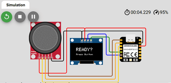
Finite State Machine (FSM)
As logic complexity increased, multiple boolean flags became confusing. I implemented a Finite State Machine using an enum:
- WAIT_START
- PLAYING
- GAME_OVER
Each state controls:
- What is drawn
- What logic runs
- How transitions occur
Transitions are triggered by button interrupt or game-over condition, simplifying the architecture and improving scalability.
Using an Interrupt for the Start Button
pinMode(startButton, INPUT_PULLUP);
attachInterrupt(..., FALLING);
Instead of polling continuously, I used a hardware interrupt.
The ISR only sets a volatile flag, while the main loop
handles state transitions. This enabled event-driven behavior.
Embedded System Concepts Applied
- ADC signal interpretation
- Dead zone implementation
- Signed integer physics modeling
- Collision detection logic
- Frame-based rendering
- Finite State Machine architecture
- Hardware interrupt handling
What started as a simple joystick + display experiment evolved into a structured real-time embedded system.
Gameplay Demonstration
5. Challenges, Errors and Debugging Process
During development, several issues appeared. Instead of avoiding them, I documented and analyzed each one to understand its underlying cause. Debugging was not a separate phase — it was part of the learning process.
1️⃣ 🖥️ OLED Not Detected
Problem: Serial monitor displayed “OLED Display NOT Found…” even though wiring seemed correct.
Cause: Incorrect initialization order and I2C logic configuration.
Solution: Verified I2C address (0x3C), SDA/SCL mapping,
and correct Wire.begin() usage. Reinforced the importance of
understanding library initialization instead of assuming hardware failure.
2️⃣ 📊 Serial Plotter Not Displaying Data
Cause: Printed text together with numeric values:
Serial.print("Potentiometer:");
Serial.println(value);
Solution: Output pure numeric data only:
Serial.println(value);
This highlighted how formatting directly affects debugging tools.
3️⃣ 🎾 Ball Blinking but Not Moving
Cause: Movement function was written but not called inside loop().
Solution: Corrected execution order: Update physics → Clear display → Draw → display.display().
4️⃣ 💡 Screen Flickering
Cause: Multiple calls to display.display() per frame.
Solution: Consolidated rendering into a single buffer transfer per frame, eliminating flicker and stabilizing visuals.
5️⃣ 🔄 Incorrect Rebound in Corners
Cause: Both X and Y axes modified simultaneously during wall collision.
Solution: Separated axis logic:
Horizontal collision → invert velX
Vertical collision → invert velY
6️⃣ ⚠️ Unsigned Velocity Overflow
unsigned int velX;
velX = -velX;
Cause: Unsigned integers cannot represent negative values.
Solution: Replaced with signed integers (int).
Critical lesson about numeric types in embedded systems.
7️⃣ 🚫 Immediate Game Over at Start
Cause: Ball initialized too close to boundary.
Solution: Adjusted initial position and refined boundary detection.
8️⃣ 🎮 Game Over Screen Not Displayed
Cause: Mixed rendering and logic using multiple boolean flags.
Solution: Implemented Finite State Machine: WAIT_START → PLAYING → GAME_OVER.
9️⃣ 🔧 Interrupt Function Not Declared
Cause: ISR used before declaration.
Solution: Declared handleStart() before setup().
Reinforced understanding of C++ compilation order.
Reflection on the Debugging Process
Each error forced me to re-read documentation, review the datasheet, reconsider assumptions, and improve system structure.
Debugging was not separate from learning — it was the learning process itself.
General Reflection
This week marked a significant transition in my understanding of embedded systems. What began as independent experiments with GPIO, ADC readings, and display communication evolved into the design of a structured, real-time interactive system.
One of the most important insights was realizing that embedded programming is not only about writing code that works, but about understanding how hardware constraints influence software architecture. Reading the ESP32-C3 datasheet allowed me to move beyond abstraction and understand the microcontroller’s internal capabilities — including ADC resolution, peripheral mapping, interrupt handling, and processor architecture.
The transition from raw analog values to structured control logic reinforced the importance of signal interpretation. Concepts such as resolution versus precision, dead zones, scaling, and noise management became practical tools rather than theoretical ideas.
Implementing ball physics and collision detection required careful thinking about numeric types, execution order, and system state. Small implementation details — such as using signed integers or separating rendering from logic — had significant effects on system stability.
The introduction of a Finite State Machine and hardware interrupts represented a conceptual shift toward event-driven design. Instead of building a sequence of instructions, I structured the system as a coordinated interaction between inputs, logic, and rendering phases.
Perhaps the most valuable lesson came from debugging. Every error revealed something about timing, architecture, numeric behavior, or communication protocols. Debugging was not a separate activity from development — it was the mechanism through which understanding deepened.
By the end of this assignment, I was no longer simply reading analog inputs or updating a display. I had designed a small but complete embedded system with structured logic, physics modeling, state management, and real-time interaction.
Individual Reflection – Group Assignment
Through the comparative analysis of different embedded platforms, I gained a deeper understanding of how processor architecture directly impacts toolchain selection, development workflow, and overall system capability. Moving from AVR to Xtensa and then to RISC-V and ARM architectures clearly shows the evolution of embedded systems toward higher performance and greater flexibility.
Although Arduino (ATmega328P – AVR) remains an excellent platform for learning fundamentals, its 8-bit architecture, limited memory, and lack of native wireless connectivity make it less competitive for modern embedded applications. For projects involving multitasking, communication protocols, or IoT functionality, more advanced 32-bit platforms provide significantly better scalability.
Among the evaluated systems, the ESP32 ecosystem stands out as the most complete solution due to its strong hardware capabilities, integrated WiFi and Bluetooth, 12-bit ADC resolution, and broad peripheral support. The ESP32-S3 is especially suitable for projects requiring multiple inputs and outputs or higher processing performance, while the XIAO ESP32-C3 offers an excellent balance between compact size and modern RISC-V processing power.
The Raspberry Pi Pico (RP2040) impressed me with its clean workflow and dual-core architecture, but the absence of native wireless connectivity limits its versatility compared to ESP32-based solutions.
Overall, this group comparison reinforced that selecting a microcontroller is not only about writing code. It requires evaluating architecture, ecosystem maturity, connectivity needs, hardware peripherals, and development complexity. Capability and configuration effort grow together, and choosing the right platform depends on the technical requirements and constraints of the project.
Downloads & Resources
This section provides access to the external simulations and downloadable resources developed during the Embedded Programming assignment. The project includes Arduino source code for the XIAO ESP32-C3 together with interactive Wokwi simulations used to validate the programs before hardware implementation.
🔗 References & Simulations
The following Wokwi simulations were created to test analog inputs, OLED communication, and interactive embedded applications before programming the physical XIAO ESP32-C3 development board.
📁 Downloadable Files
To improve the loading performance of this documentation website, all downloadable resources have been moved to a shared Google Drive folder.
The repository contains the complete Arduino source code, project files, firmware examples, and supporting documentation developed during the Embedded Programming assignment.
Additional examples and updated program versions may be added as the project continues to evolve.