Assignment Requirements
- Design, laser cut, and document a parametric construction kit, accounting for the laser cutter kerf.
- Cut something using the vinyl cutter.
Learning Outcomes
- Demonstrate and describe parametric 2D modeling processes.
- Identify and explain the processes involved in using the laser cutter.
- Develop, evaluate, and construct a parametric construction kit.
- Identify and explain the processes involved in using the vinyl cutter.
Progress Status
Summary of completed tasks for Week 03.
Design and development of a fully parametric construction kit using 2D modeling tools, focused on modularity and press-fit assembly.
Preparation of files, machine setup, material selection, and fabrication of the parametric kit using the laser cutter.
Design and fabrication of a vinyl-cut graphic, including vector file preparation and cutting workflow.
Parametric Plant Stand Design
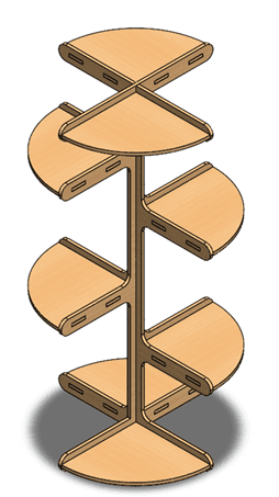
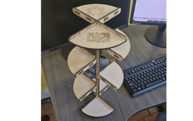
For the parametric construction kit, I designed a plant stand intended to organize the plants my wife and I have at home. The objective was to create a modular, scalable structure that could be easily adapted by modifying a limited number of parameters.
The design process started with a conceptual sketch inspired by larger commercial plant stands, later adapted to a laser-cut structure using 4 mm MDF as a test material.
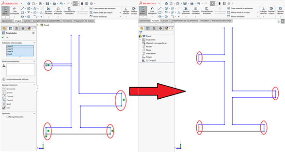
Sketch Relations and Structural Logic
Each part was designed using parametric sketch relations instead of relying solely on dimensions. Relations such as horizontal, vertical, equal, and collinear were applied to control alignment, direction, and proportionality.
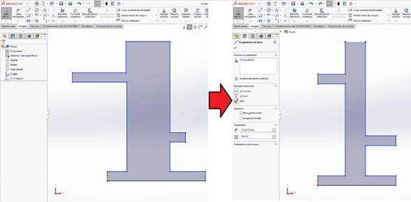
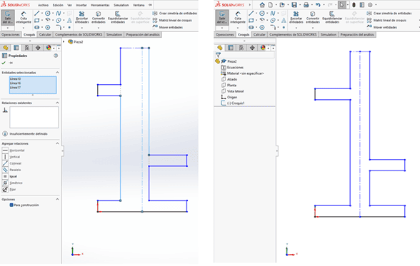
Symmetry relations were used to ensure balance and consistency across the design. By defining reference axes, mirrored features remained equidistant without adding redundant dimensions.
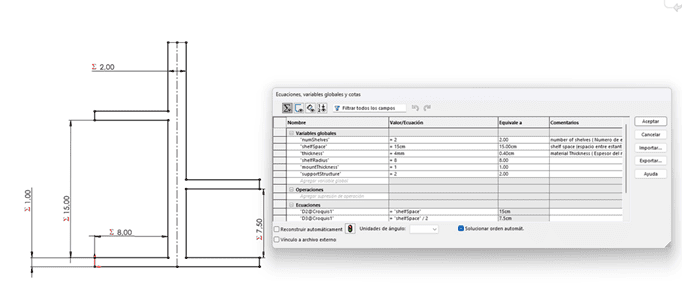
Global Variables and Equations
Once the sketch behavior was defined, global variables were created to control critical parameters such as total height, shelf spacing, shelf width, material thickness, and number of shelves.
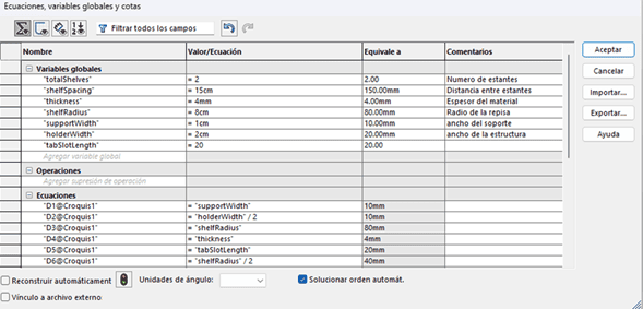
These variables were linked to both sketch dimensions and feature parameters, ensuring that the entire model responded consistently to any change.
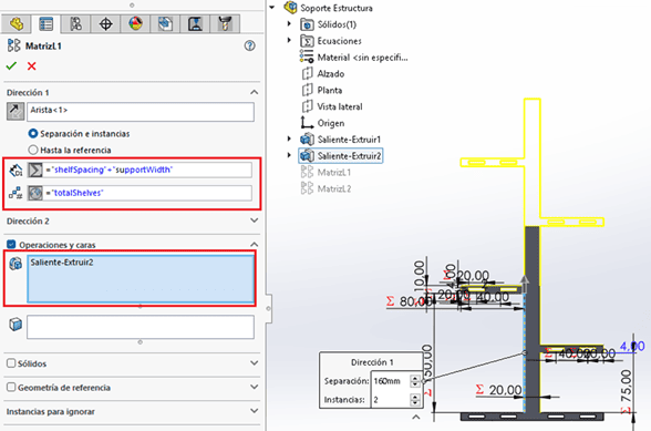
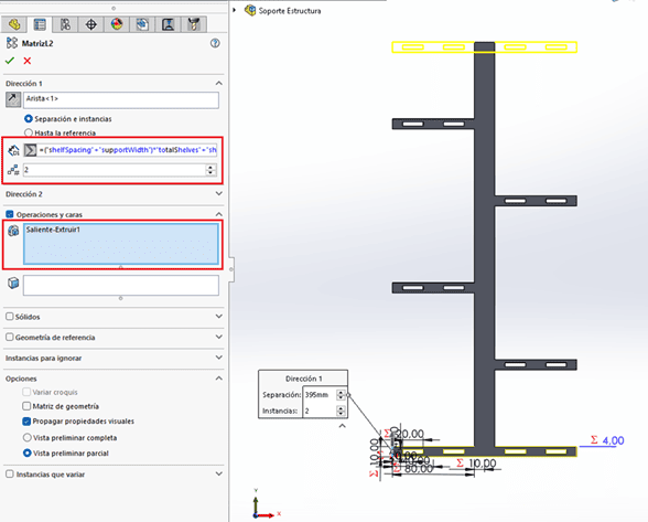
Parametric Linear Patterns
After extruding the base geometry, linear pattern features were used to replicate the shelves vertically. Both the spacing and the number of instances were controlled using global variables.
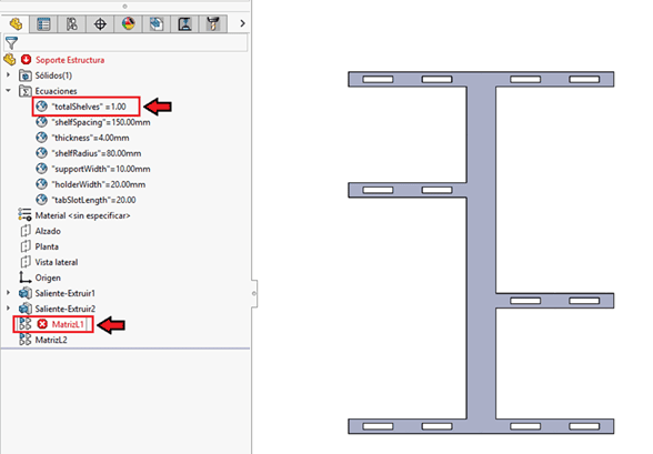
Parametric Error Identified
During testing, a parametric error occurred when the global variable
totalShelves was set to a value of 1. Linear pattern
features require more than one instance, and when this condition was not met,
SolidWorks generated errors that propagated through the model.
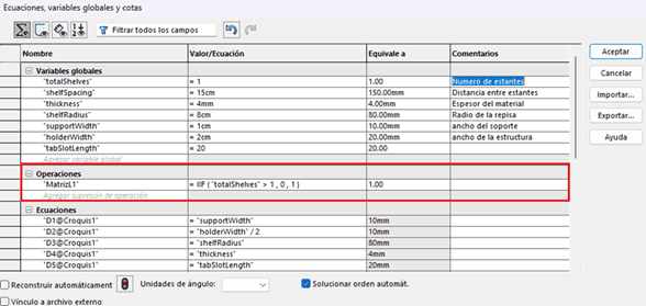
Conditional Suppression Solution
To solve this issue, I implemented a conditional suppression strategy using the
IIF() function within the equations table. This function allows
operations to be automatically suppressed based on a logical condition.
In this case, the linear pattern feature is suppressed when
totalShelves ≤ 1, preventing SolidWorks from attempting to generate an
invalid pattern.
Parametric Consistency Across Parts
The shelf component was designed using the same global variables as the main structure. These variables were exported to a text file and imported into the new part, ensuring full parametric consistency across all components.

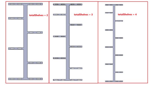
Fully Parametric Assembly
The final assembly was created using component linear patterns, resulting in a fully parametric system where the number of shelves, shelf size, and total height can be modified without breaking mates or constraints.
Parametric Behavior Demonstration
The following video demonstrates how modifying a small set of parameters dynamically updates the number of shelves, shelf dimensions, and overall height, while preserving the integrity of both the parts and the assembly.
Laser Cutting Process
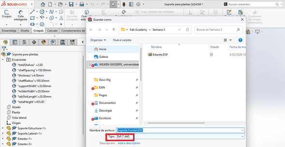
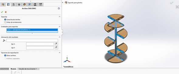
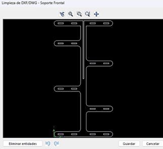
1. DXF Export from SolidWorks
Once the parametric model was finalized, the cutting profiles were exported as DXF files directly from SolidWorks. This was done using the surface export tool, which allows generating vector geometry from selected faces without redrawing the design.
This workflow ensures that any modification in the parametric model can be updated and re-exported quickly, maintaining design accuracy.
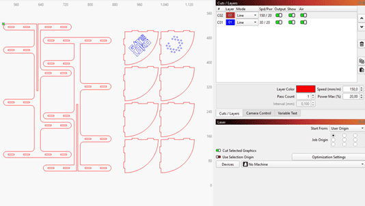
2. Layout Preparation in LightBurn
The DXF files were imported into LightBurn, where the layout of all parts was arranged to optimize material usage and reduce waste.
Cutting and engraving operations were assigned to different layers, allowing independent control of speed and power settings.
3. Material and Fit Strategy
The fabrication material was 4 mm MDF. A kerf compensation value of 0.15 mm was applied to achieve a tight press-fit between components.
The objective was to ensure structural stability without using adhesives, relying only on friction-fit joints.
4. Cutting and Engraving Process
During fabrication, both cutting and engraving operations were executed. Two panels were engraved with my band logo and the university logo, demonstrating multi-operation workflow within the same setup.
Laser Cutting Video
The following video shows the laser cutting process in operation, including engraving and contour cutting of the MDF sheet.
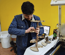
5. Final Assembly
After fabrication, all parts were carefully removed from the machine bed and assembled manually. The press-fit joints worked as expected, confirming that the applied kerf compensation ensured accurate alignment and structural rigidity.
Vinyl Cutting
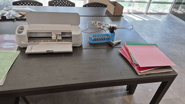
1. Machine Overview
The vinyl cutting assignment was performed using a Cricut Maker 3 available at the Fab Lab. This desktop cutting machine operates using vector paths to precisely cut thin materials such as adhesive vinyl.
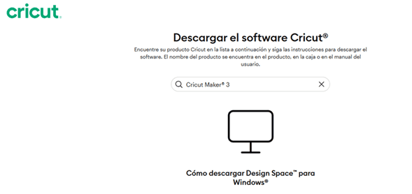
2. Software Setup
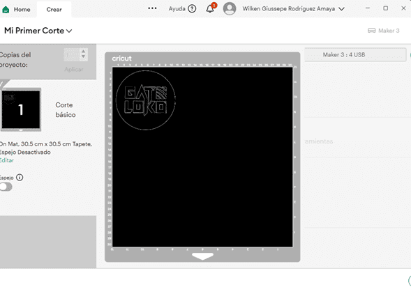
To operate the machine, the official software Cricut Design Space was downloaded and installed. After installation, an account was created and a new blank workspace was initialized.
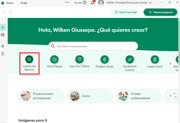
3. Vector File Import
A vector file containing my rock band logo, “Gato Loko”, was imported into the workspace. Since vinyl cutting requires vector geometry rather than raster images, the file was verified to ensure that all paths were properly defined.

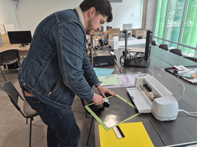
4. Material Preparation
The vinyl sheet was placed on a 30 × 30 cm cutting mat, ensuring proper alignment to avoid displacement during the cutting process. The mat was then loaded into the machine.
5. Cutting Operation
After confirming material settings, the cutting process was started. The machine followed the vector contours and completed the job in approximately five minutes.
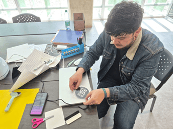
6. Weeding and Transfer
Once the cutting operation finished, the excess vinyl was removed in a process known as weeding, leaving only the desired graphic. Transfer tape was then applied to lift the design from the backing layer.
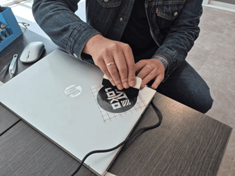
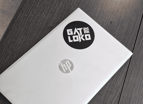
7. Final Application
The sticker was applied to the back surface of my laptop. A scraper tool was used to ensure proper adhesion and eliminate air bubbles, resulting in a clean and professional finish.
Reflection
This week reinforced the importance of parametric thinking in digital fabrication. Instead of designing static geometry, I focused on building a system controlled by variables, equations, and logical relationships. This approach significantly improves adaptability and scalability.
One of the most valuable lessons was understanding that parametric modeling is not only about linking dimensions, but about anticipating potential failures. The issue encountered with the linear pattern when the number of shelves was set to one highlighted how important it is to think beyond geometry and consider feature logic. Implementing conditional suppression using the IIF() function transformed a model error into a robust solution.
The transition from CAD to fabrication also emphasized the relationship between digital design and physical constraints. Applying kerf compensation and validating press-fit joints demonstrated how small dimensional adjustments directly affect structural performance.
In the laser cutting workflow, I gained a clearer understanding of file preparation, layer control, and multi-operation management (cutting and engraving). The ability to move seamlessly from a parametric model to a manufacturable DXF file reinforces the value of maintaining clean and structured design logic.
The vinyl cutting assignment, although simpler, highlighted the importance of vector-based workflows and material preparation. Even small fabrication tasks require attention to detail, precision, and process understanding.
Overall, this week strengthened my confidence in parametric modeling and computer-controlled cutting processes. More importantly, it reinforced a mindset: design should not only define shape, but define behavior.
Downloads & Resources
This section provides access to the design resources and downloadable files created during the Computer-Controlled Cutting assignment. The project includes parametric CAD models, laser cutting files, and LightBurn projects used throughout the fabrication workflow.
🛠️ Project Resources
This assignment was developed using parametric CAD software and laser cutting preparation tools. The project resources include design models, manufacturing files, and machine configuration projects used to validate the fabrication process.
- ✅ Parametric CAD Models (SolidWorks)
- ✅ DXF Files for Laser Cutting
- ✅ LightBurn Engraving Projects
- ✅ Kerf Calibration Tests
- ✅ Power & Speed Test Files
📁 Downloadable Files
To improve the loading performance of this documentation website, all project files have been moved to a shared Google Drive folder.
The repository contains the complete SolidWorks project, DXF files, LightBurn projects, laser cutting test files, and additional resources required to reproduce the fabrication workflow.
Updated versions and additional documentation may be added as the project continues to evolve.