Individual Assignment Requirements
- Make (design + mill + assemble) something big.
- Demonstrate 2D design development for CNC milling production.
- Describe workflows and operation for large format CNC machining.
Learning Outcomes
- Develop 2D parametric designs for CNC milling.
- Prepare files for large format machining.
- Understand stock preparation and workholding.
- Document assembly and structural stability.
Progress Status - CNC Bookshelf Project
Complete workflow from design to final assembly.
Developed a fully parametric system in SolidWorks using global variables and linked equations for scalable design.
Generated toolpaths in Fusion 360, including nesting, dogbones, and multi-step cutting strategy.
Fabricated parts using CNC router, including machine setup, calibration, and multi-session machining process.
Cleaned parts, removed burrs, and assembled the structure using press-fit joints without glue or screws.
1. Project Description - Modular Hexagonal Bookshelf
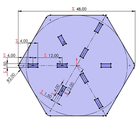
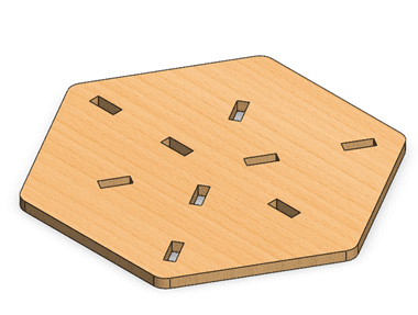
The project consists of a modular bookshelf with a hexagonal base geometry. The design is based on parametric modeling principles developed in Week 03, allowing flexible adjustment of dimensions and number of levels.
The structure was designed to be fully assembled without glue, screws, or additional hardware. All joints rely on press-fit tolerances calculated according to the 12 mm plywood thickness.
The modular system allows the incorporation of additional floors, making the bookshelf scalable and adaptable.
1. Parametric Design Development - SolidWorks
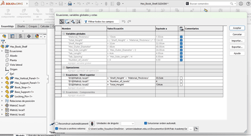
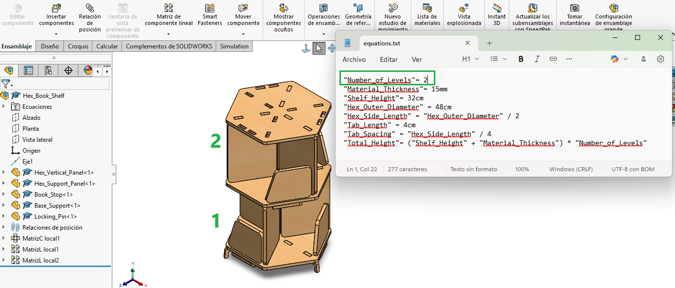
The bookshelf was developed using a fully parametric workflow in SolidWorks. Global variables and linked equations were defined to control critical dimensions such as material thickness, hexagonal base geometry, slot width, structural height, and floor spacing.
All dimensional relationships were exported and managed through an external .txt equation file, allowing centralized control of the entire design system. This approach ensures that modifying a single variable automatically updates all related components.
The project consists of 7 different parts, all parametrically linked to the same equation file. This guarantees geometric consistency and structural coherence across the entire assembly.
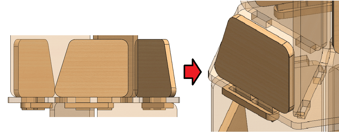
For the assembly stage, retention pins were integrated into the outer book supports to reduce mechanical wear caused by torsional stress from book weight. This reinforcement improves structural durability without compromising the modular press-fit concept.
The parametric strategy enables scalable customization, allowing the number of floors to be modified dynamically without redesigning each individual component.
2. CAM Processing and Toolpath Strategy - Fusion 360
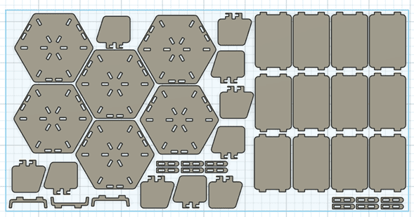
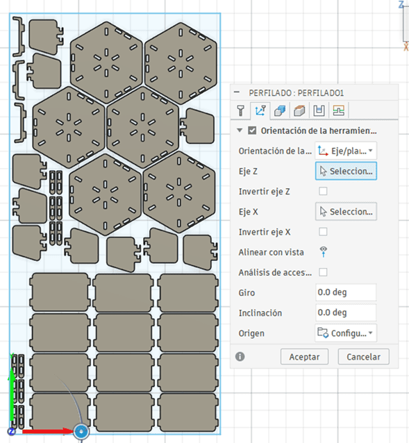
The SolidWorks parametric parts were first imported into Fusion 360. All components were arranged on the TOP plane, matching the real plywood sheet dimensions: 1220 mm x 2440 mm.
Proper nesting was performed to optimize material usage while maintaining safe spacing between parts.
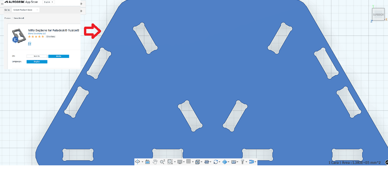
The DogBone plugin was installed and applied to all internal corners. Since CNC milling uses a cylindrical tool, sharp internal 90° corners cannot be produced. Without dogbone fillets, the rounded tool radius would prevent proper press-fit assembly.
By applying dogbone corrections, internal joints were modified to ensure accurate interlocking between components.
In the Manufacturing workspace, the cutting strategy was defined using the parameters tested during the group assessment.
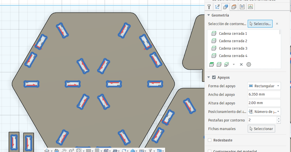
Two separate 2D Contour operations were created:
- First operation: internal holes and slots
- Second operation: outer profile cutting
Although my tutor mentioned it was not strictly necessary, I chose to separate the operations as a precaution. This ensures that small internal features are completed before the final outer cut releases the part from the sheet.
Cutting parameters were adjusted to reduce material burning:
- Feed rate: 150 mm/min
- Spindle speed: 3500 RPM
These parameters were selected to prevent overheating and excessive edge charring observed during group tests.
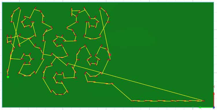
Finally, a full simulation was executed to verify toolpath behavior, cutting order, and collision safety before exporting the G-code.
3. CNC Fabrication and Machine Setup
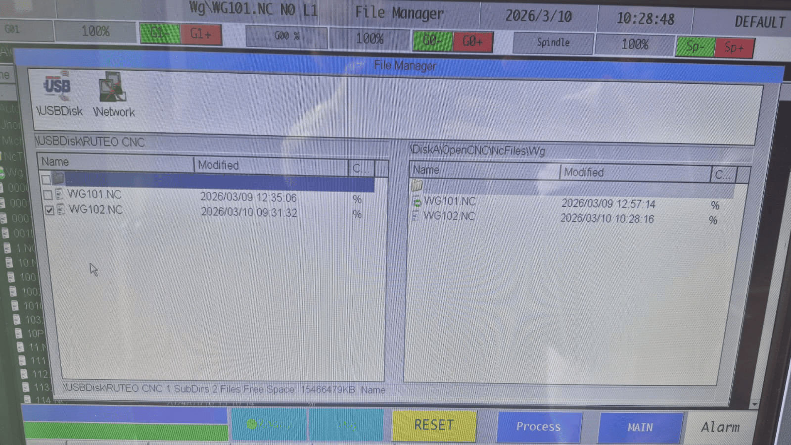
After completing the CAM preparation, the G-code file was exported using the post-processing tool and uploaded to the CNC router controller.
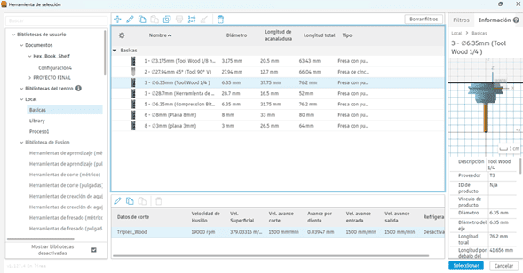
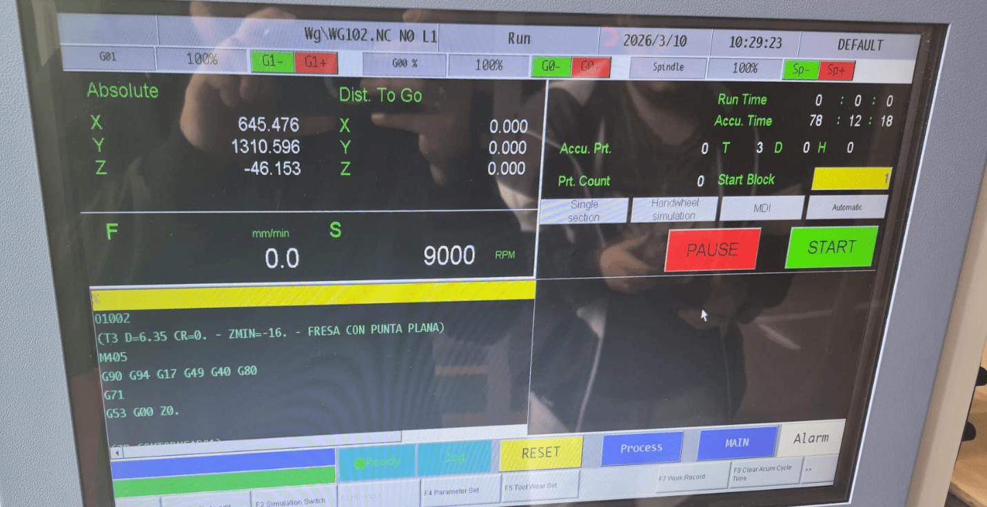
The milling bit was installed in tool position 3, and manual calibration was performed to determine the minimum Z reference.
Using the manual positioning controls, the work origin (X, Y) and the ΔZ offset were configured to correctly align the plywood sheet within the machine coordinate system.
Before starting the process, the preview function on the CNC control screen was used to verify the cutting sequence and estimated machining time.
The total estimated time was approximately 10 hours, which required dividing the fabrication into multiple cutting sessions.
Identified Error and Correction
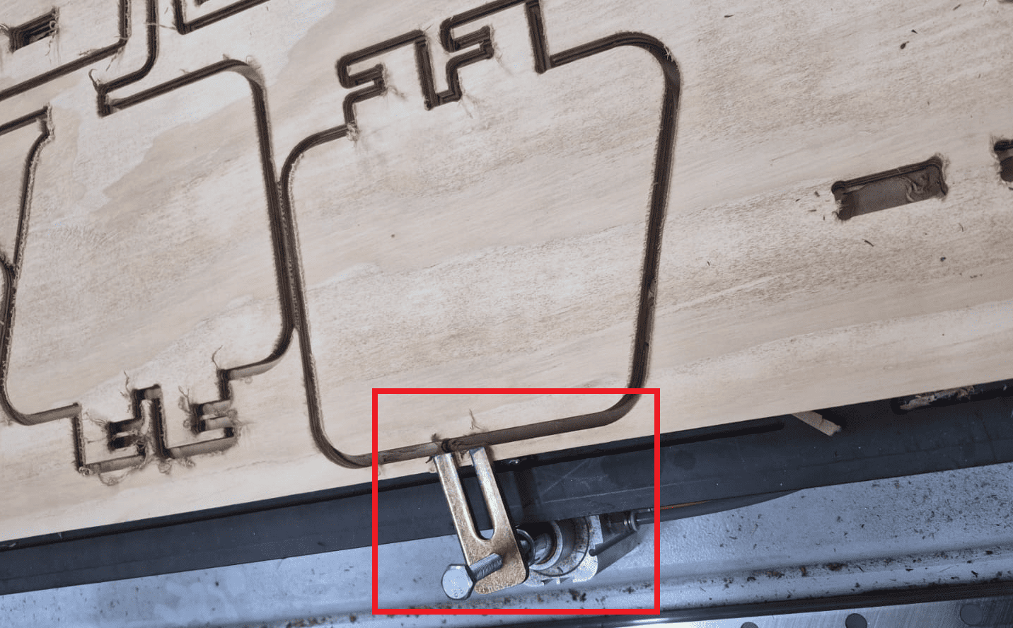
During the first cutting attempt, an error occurred due to improper planning of the clamping system.
The layout was positioned without accurately accounting for the physical space occupied by the pneumatic clamps. The placement was estimated visually instead of measured precisely.
As a result, the CNC tool collided with one of the metallic pneumatic clamps, partially cutting it.
The process was immediately stopped, the material was repositioned, and the layout was adjusted to maintain safe clearance from all clamping components.
This experience reinforced the importance of:
- Accurate measurement of clamping zones
- Planning safe machining boundaries
- Never relying on visual estimation
- Simulating real-world constraints beyond digital models
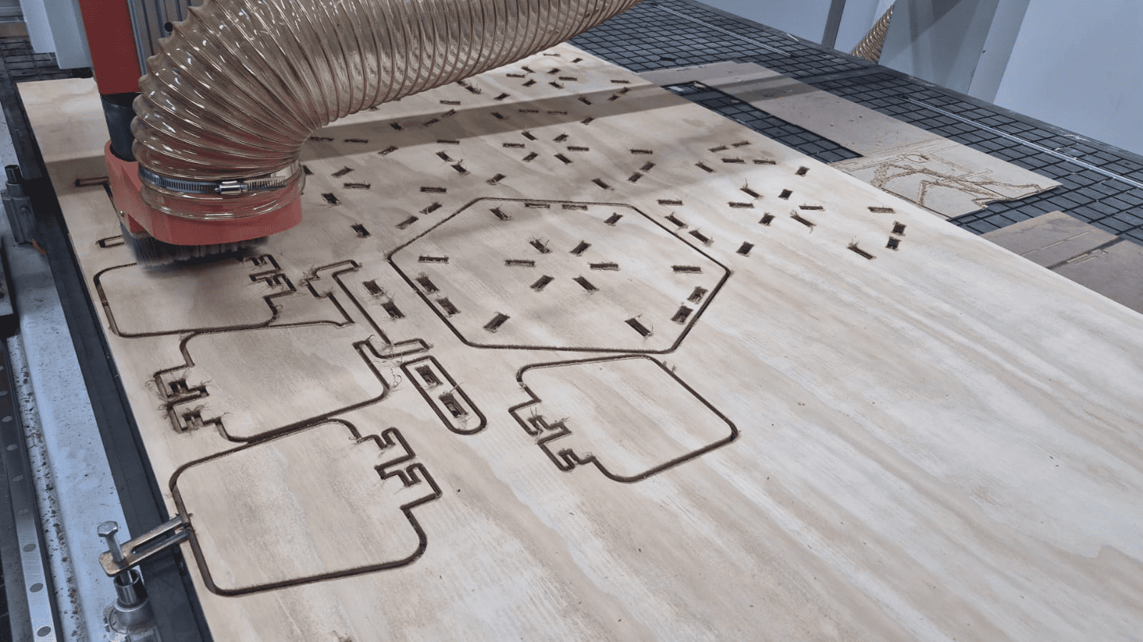
After correcting the layout, the machining process continued successfully.
4. Post-Processing and Assembly
Material Cleaning and Finishing
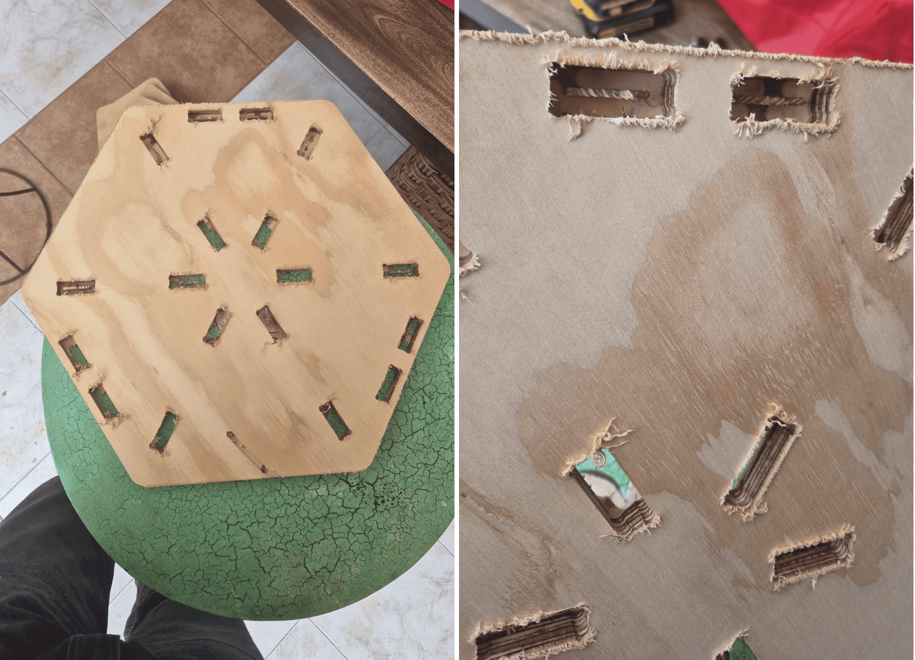
After the CNC machining process, the wooden parts presented a significant amount of burrs and excess material, especially along the edges and internal cuts.
To clean and refine the pieces, I used an oscillating multitool (DeWalt), which allowed controlled material removal without damaging the geometry of the parts.
This step was essential to ensure proper fitting during assembly, as even small imperfections can affect press-fit joints.
Post-Processing Process
Assembly Process
Once all parts were properly cleaned, the assembly process began. The structure was designed using press-fit joints, eliminating the need for glue or screws.
Due to the tight tolerances defined in the parametric design, the assembly required applying controlled force to fit the parts together.
In some cases, a small mallet was used to assist the insertion of joints, ensuring a firm and stable connection.
The full assembly process took approximately 20 minutes, resulting in a rigid and self-supporting structure.
Assembly Process (Timelapse)
Assembly process shown in accelerated time (x10).
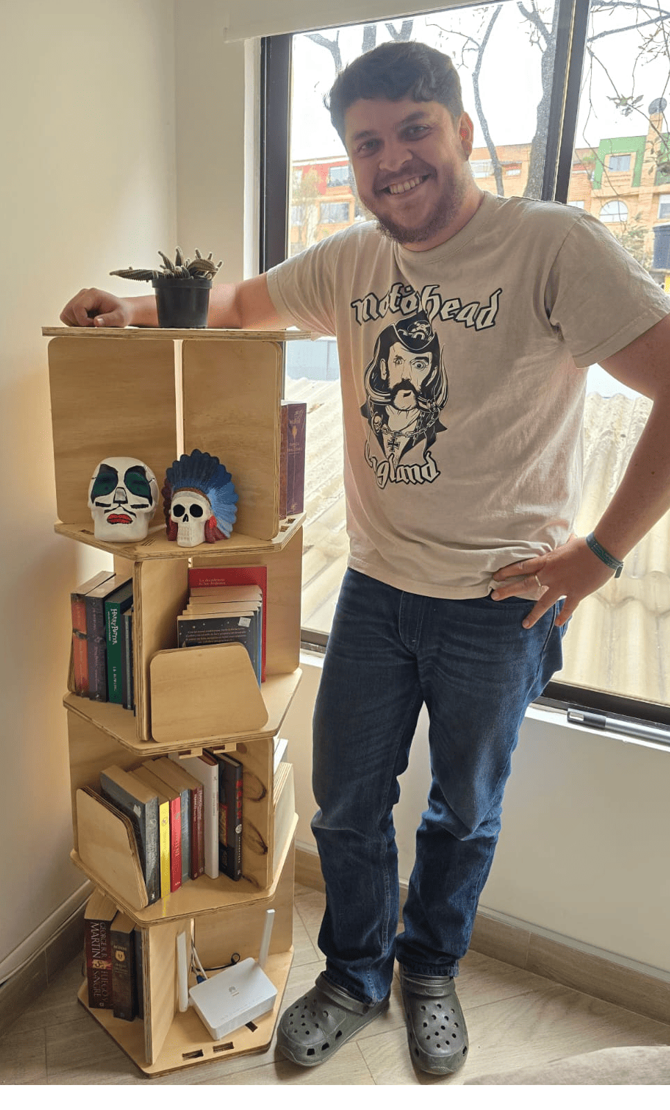
Final Result - Hero Shot
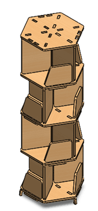
The final result is a modular hexagonal bookshelf fully assembled and integrated into a real environment. The structure successfully supports multiple books and decorative elements, demonstrating both functional stability and aesthetic coherence.
The press-fit design proved to be highly effective, as all joints were assembled without the need for glue, screws, or additional fastening elements. The tight tolerances defined during the parametric design phase ensured a rigid and self-supporting structure.
This project highlights how computer-controlled machining can be used to fabricate large-scale objects with high precision, where design decisions directly influence assembly behavior and structural performance.
Additionally, the modular nature of the bookshelf allows scalability and adaptability, enabling the addition of more levels or reconfiguration of the structure depending on user needs. This demonstrates the potential of parametric design combined with CNC fabrication for creating customizable and functional furniture.
Final Reflection
This week provided a comprehensive understanding of the complete workflow involved in computer-controlled machining, from parametric design to large-scale fabrication and physical assembly.
One of the most important insights was the role of parametric design in controlling complex systems. By defining global variables and linking all components through a centralized equation file, the entire structure became scalable and adaptable. This approach allowed modifying dimensions and configuration without redesigning each individual part.
The CAM process in Fusion 360 reinforced the importance of translating design into manufacturable geometry. Operations such as nesting, toolpath separation, and the use of dogbone fillets demonstrated how digital models must be adapted to the physical limitations of CNC tools. Understanding tool diameter and cutting behavior was essential to ensure proper press-fit assembly.
During the CNC fabrication stage, I learned that machine setup and planning are as critical as the design itself. The collision with the clamp highlighted the importance of considering real-world constraints that are not always visible in the digital environment. This experience emphasized the need for accurate measurement, proper workholding strategies, and safety-aware planning.
The post-processing phase revealed how material behavior affects final results. Removing burrs and imperfections was necessary to achieve proper fitting, showing that fabrication does not end with machining, but continues through finishing and adjustment.
The assembly process demonstrated the effectiveness of press-fit joints. Tight tolerances allowed the structure to be assembled without glue or screws, resulting in a rigid and stable system. This reinforced the importance of precision in both design and machining, as small deviations can significantly affect assembly performance.
Overall, this week highlighted that CNC fabrication is not just about cutting material, but about understanding the relationship between design, tools, materials, and assembly. Each stage influences the next, and successful results depend on integrating all these factors into a coherent workflow.
This experience strengthened my ability to design for manufacturing, anticipate fabrication constraints, and approach large-scale projects with a more systematic and engineering-oriented mindset.
Individual Reflection
This assignment allowed me to fully understand the relationship between parametric design, CNC machining, and physical assembly. Designing a large-scale object required thinking beyond geometry and considering how each decision would affect fabrication and final usability.
One of the most important lessons was the importance of designing for manufacturing. Parameters such as material thickness, tolerances, and tool diameter directly influenced the performance of press-fit joints. Even small variations in machining or material behavior could significantly impact the assembly process.
The CAM workflow reinforced how digital models must be adapted to real-world constraints. Features such as dogbone fillets and toolpath sequencing were essential to ensure that parts could be correctly fabricated and assembled.
During fabrication, I learned that machine setup and planning are critical. The collision with the clamp highlighted the importance of considering physical constraints that are not always visible in the digital environment. This experience emphasized the need for precision, safety awareness, and careful preparation before machining.
The post-processing and assembly stages demonstrated how material behavior affects the final result. Removing burrs and adjusting tight joints required additional effort, confirming that CNC machining is not only about cutting, but also about finishing and fitting.
Finally, this project showed that press-fit design can be a powerful strategy for creating strong and modular structures without additional hardware. The final bookshelf validated the complete workflow from digital design to physical product.
Overall, this week strengthened my ability to approach large-scale fabrication projects with a more integrated and engineering-oriented mindset, considering design, machining, and assembly as a unified process.
Downloads & Resources
This section provides access to the design resources and downloadable files created during the Computer-Controlled Machining assignment. The repository includes the complete CNC workflow, from parametric design and CAM preparation to machine configuration and G-code generation.
🛠️ Project Resources
The project repository contains all files required to reproduce the modular bookshelf, including CAD designs, CAM setup, CNC machine configuration, and machining programs.
- ✅ SolidWorks Parametric Design Files
- ✅ Fusion 360 CAM Project
- ✅ Syntec CNC Post Processor (.cps)
- ✅ CNC G-Code Program (.nc)
- ✅ Syntec Machine Configuration (.mch)
- ✅ CNC Tool Library & Project Assets
📁 Downloadable Files
To improve the loading performance of this documentation website, all project files have been moved to a shared Google Drive folder.
The repository contains the complete CAD models, CAM setup, Syntec post processor, CNC machining program, machine configuration files, and supporting documentation developed during this assignment.
Additional machining strategies, updated tool libraries, and future design revisions may be added as the project evolves.