Group Assignment
- Send a message between two independent embedded projects.
- Demonstrate wireless communication using an embedded networking protocol.
- Document the communication workflow on the group work page.
- Reflect on the learning experience on the individual page.
Learning Outcomes
- Understand the workflow required to establish communication between embedded devices.
- Configure peer-to-peer wireless communication using ESP-NOW.
- Exchange data reliably between two ESP32-based systems.
Project Context
This group assignment demonstrates wireless communication between two independent embedded systems using the ESP-NOW protocol. Unlike conventional Wi-Fi communication, ESP-NOW allows ESP32 devices to exchange data directly without requiring a wireless router or internet connection, making it an efficient solution for low-latency embedded applications.
The system was implemented using two Seeed Studio XIAO ESP32-C3 development boards. One board acts as the transmitter, reading two push buttons and sending a message whenever one of them is pressed. The second board acts as the receiver, listening for incoming ESP-NOW packets and displaying the received value on an SSD1306 OLED display through the I²C interface.
Communication Workflow
Before communication can begin, both ESP32 boards must identify their unique MAC addresses and register each other as trusted peers. Once paired, the transmitter sends an integer value whenever a button is pressed, and the receiver automatically processes the incoming packet through an event-driven callback function, updating the OLED display in real time.
This architecture demonstrates how multiple embedded systems can cooperate wirelessly, combining digital inputs, peer-to-peer networking, and graphical feedback without relying on external networking infrastructure.
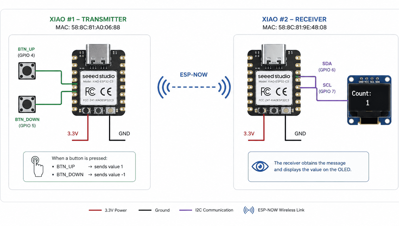
System architecture showing the ESP-NOW communication between two XIAO ESP32-C3 boards. The transmitter reads two push buttons and sends the corresponding command wirelessly to the receiver, which displays the received value on an SSD1306 OLED display.
Device Identification – MAC Address
Unlike traditional Wi-Fi communication, ESP-NOW establishes a direct peer-to-peer connection between ESP32 devices. Each board is identified by a unique 48-bit MAC (Media Access Control) address, which acts as its hardware identifier on the wireless network.
Before sending any data, both XIAO ESP32-C3 boards must discover their own MAC addresses. These addresses are then used to register each board as a trusted peer, allowing secure point-to-point communication without requiring a Wi-Fi router.
Detected Devices
| Device | Role | MAC Address |
|---|---|---|
| XIAO ESP32-C3 #1 | Transmitter | 58:8C:81:A0:06:88 |
| XIAO ESP32-C3 #2 | Receiver | 58:8C:81:9E:48:08 |
Key Functions
-
WiFi.mode(WIFI_STA)configures the ESP32 as a Wi-Fi station. -
WiFi.macAddress()retrieves the unique MAC address stored in the ESP32 wireless interface. -
Serial.println()prints the address through the USB serial monitor for later use during peer configuration.
#include <WiFi.h>

void setup() {

  Serial.begin(115200);
  delay(1000);

  WiFi.mode(WIFI_STA);

  Serial.println("Getting MAC Address...");

  Serial.print("MAC: ");
  Serial.println(WiFi.macAddress());

}

void loop() {

}
ESP-NOW uses the MAC address as the destination identifier for every transmitted packet. Instead of connecting through an access point, the transmitter sends data directly to the receiver by specifying its MAC address when registering the communication peer.
Code Explanation
#include <WiFi.h>
Imports the ESP32 Wi-Fi library, which provides access to the wireless interface and allows the program to retrieve the device's MAC address.
Serial.begin(115200)
Initializes the serial communication used to print the detected MAC address to the Arduino IDE Serial Monitor.
WiFi.mode(WIFI_STA)
Configures the ESP32 as a Wi-Fi Station (STA). ESP-NOW requires the wireless interface to be initialized in Station mode before any peer-to-peer communication can be established.
WiFi.macAddress()
Reads the unique 48-bit MAC address stored in the ESP32 hardware and returns it as a formatted string. This address is later used to identify the board when configuring ESP-NOW peers.
loop()
No continuous execution is required for this sketch because the MAC address only needs to be printed once during startup.
ESP-NOW Transmitter
Once both XIAO ESP32-C3 boards were identified, the first device was configured as the ESP-NOW transmitter. Its purpose is to continuously monitor two push buttons and send a wireless message whenever the user presses one of them.
The transmitted packet contains a single integer value representing the user's
action. A value of 1 is sent when the UP button
is pressed, while -1 is transmitted when the
DOWN button is activated. These packets are delivered directly
to the receiver using its MAC address without requiring a Wi-Fi router.
Communication Workflow
- Initialize ESP-NOW.
- Register the receiver as a communication peer.
- Read both push buttons.
- Detect a new button press.
- Create the message structure.
- Transmit the packet wirelessly.
BTN_UP →
accion = 1BTN_DOWN →
accion = -1
Code Explanation
typedef struct
Defines the structure of the packet transmitted through ESP-NOW.
In this experiment the packet contains a single integer named
accion.
esp_now_init()
Initializes the ESP-NOW protocol. If initialization fails, communication cannot begin.
esp_now_add_peer()
Registers the receiver using its MAC address. This creates a trusted peer that can receive wireless packets from the transmitter.
digitalRead()
Reads the state of both push buttons to detect user interaction. The previous state is stored to identify only new button presses.
esp_now_send()
Sends the message structure directly to the receiver through ESP-NOW using the receiver's MAC address.
#include  <WiFi.h <
#include  <esp_now.h<

#define BTN_UP    4
#define BTN_DOWN  5

typedef struct {
  int accion;
} mensaje_t;

mensaje_t msg;

// Reemplazar por la MAC real
uint8_t receptorMAC[] = {0x64,0xE8,0x33,0x12,0x34,0x56};

bool lastUp = HIGH;
bool lastDown = HIGH;

void setup() {

  Serial.begin(115200);

  pinMode(BTN_UP, INPUT_PULLUP);
  pinMode(BTN_DOWN, INPUT_PULLUP);

  WiFi.mode(WIFI_STA);

  if (esp_now_init() != ESP_OK) {
    Serial.println("Error ESPNOW");
    return;
  }

  esp_now_peer_info_t peerInfo = {};

  memcpy(peerInfo.peer_addr, receptorMAC, 6);
  peerInfo.channel = 0;
  peerInfo.encrypt = false;

  esp_now_add_peer(&peerInfo);
}

void loop() {

  bool up = digitalRead(BTN_UP);
  bool down = digitalRead(BTN_DOWN);

  if (lastUp == HIGH && up == LOW) {

    msg.accion = 1;

    esp_now_send(
      receptorMAC,
      (uint8_t *)&msg,
      sizeof(msg)
    );

    delay(50);
  }

  if (lastDown == HIGH && down == LOW) {

    msg.accion = -1;

    esp_now_send(
      receptorMAC,
      (uint8_t *)&msg,
      sizeof(msg)
    );

    delay(50);
  }

  lastUp = up;
  lastDown = down;
}
Edge Detection
The variables lastUp and lastDown store the
previous state of each button. This allows the program to detect only the
transition from HIGH to LOW (button press), preventing multiple wireless
messages from being transmitted while the button remains pressed.
ESP-NOW Receiver
The second XIAO ESP32-C3 was configured as the ESP-NOW receiver. Its role is to continuously listen for incoming wireless packets sent by the transmitter. Every received message contains an integer value that is used to update a counter displayed on an SSD1306 OLED screen connected through the I²C interface.
Unlike the transmitter, the receiver does not actively poll for data. Instead, it uses an event-driven callback that is automatically executed whenever a new ESP-NOW packet arrives. This approach reduces processor usage and provides an efficient communication workflow.
Communication Workflow
- Initialize the OLED display.
- Initialize ESP-NOW.
- Register the receive callback.
- Wait for incoming packets.
- Update the counter.
- Refresh the OLED display.
accion = 1 → Increment counteraccion = -1 → Decrement counter
Code Explanation
Adafruit_SSD1306 display(...)
Creates the OLED display object using the I²C interface. The display provides real-time visual feedback of the received messages.
Wire.begin(6,7)
Initializes the I²C bus using GPIO 6 (SDA) and GPIO 7 (SCL), which correspond to the XIAO ESP32-C3 hardware connections.
esp_now_register_recv_cb()
Registers the callback function executed automatically whenever a new ESP-NOW packet is received.
memcpy()
Copies the received bytes into the message structure, allowing the transmitted integer value to be accessed safely.
actualizarPantalla()
Refreshes the OLED display every time a new message arrives, showing the updated counter value in real time.
#include <WiFi.h<
#include <esp_now.h<

#include <Wire.h<
#include <Adafruit_GFX.h<
#include <Adafruit_SSD1306.h<

#define SCREEN_WIDTH 128
#define SCREEN_HEIGHT 64

Adafruit_SSD1306 display(
  SCREEN_WIDTH,
  SCREEN_HEIGHT,
  &Wire,
  -1
);

typedef struct {
  int accion;
} mensaje_t;

volatile int contador = 0;

void actualizarPantalla() {

  display.clearDisplay();

  display.setTextSize(2);
  display.setTextColor(SSD1306_WHITE);

  display.setCursor(0, 0);
  display.println("PULSOS");

  display.setTextSize(4);
  display.setCursor(10, 25);
  display.println(contador);

  display.display();
}

void onReceive(
  const esp_now_recv_info_t *info,
  const uint8_t *incomingData,
  int len
) {

  mensaje_t msg;

  memcpy(&msg, incomingData, sizeof(msg));

  contador += msg.accion;

  actualizarPantalla();
}

void setup() {

  Serial.begin(115200);

  Wire.begin(6, 7); // SDA,SCL XIAO ESP32-C3

  if (!display.begin(
        SSD1306_SWITCHCAPVCC,
        0x3C)) {

    Serial.println("OLED no encontrada");
    while (1);
  }

  actualizarPantalla();

  WiFi.mode(WIFI_STA);

  if (esp_now_init() != ESP_OK) {

    Serial.println("Error ESPNOW");
    return;
  }

  esp_now_register_recv_cb(onReceive);
}

void loop() {
}
Event-Driven Programming
One of the most important concepts demonstrated by this receiver is
event-driven programming. Instead of continuously checking
whether a message has arrived, the ESP32 automatically executes the
onReceive() callback whenever a new ESP-NOW packet is detected.
This event-based architecture improves efficiency by allowing the processor
to remain idle until communication occurs.
volatile int contador
The keyword volatile informs the compiler that the variable
may change unexpectedly outside the normal program flow. Since
contador is modified inside the ESP-NOW callback function,
declaring it as volatile prevents compiler optimizations that
could otherwise produce incorrect behavior.
Physical Implementation
After programming both XIAO ESP32-C3 boards, the system was assembled and tested physically. One board worked as the transmitter, reading the state of two push buttons, while the second board worked as the receiver, displaying the received value on an SSD1306 OLED screen.
Since ESP-NOW uses wireless peer-to-peer communication, no router or physical data cable was required between the two projects. Each board only needed power, and the communication was established using the receiver's MAC address registered in the transmitter code.

Physical setup showing the transmitter XIAO ESP32-C3 with push buttons and the receiver XIAO ESP32-C3 connected to the OLED display.
Implementation Workflow
- Program the first XIAO ESP32-C3 as the ESP-NOW transmitter.
- Program the second XIAO ESP32-C3 as the ESP-NOW receiver.
- Connect two push buttons to the transmitter board.
- Connect the SSD1306 OLED display to the receiver through I²C.
- Power both boards independently.
- Press the buttons and verify that the OLED counter updates wirelessly.
Pressing the UP button sends
accion = 1 and increases the
counter, while pressing the DOWN button sends accion = -1
and decreases the counter on the receiver display.
Individual Reflection
This group assignment expanded my understanding of embedded communication by introducing wireless networking between independent microcontrollers. While my individual assignment focused on wired protocols such as UART and I²C, working with ESP-NOW allowed me to explore a completely different communication approach, where devices exchange information directly without requiring cables, routers, or internet connectivity.
One of the most valuable aspects of this experience was learning how peer-to-peer communication is established using MAC addresses. Understanding that each ESP32 must identify its communication partner before exchanging data helped me better appreciate how wireless embedded networks are organized. I also reinforced my knowledge of event-driven programming through the use of callback functions, which process incoming messages only when new data is received.
Another important lesson was recognizing how different communication protocols are selected according to the application requirements. UART is ideal for serial debugging, I²C efficiently connects multiple peripherals on the same board, and ESP-NOW provides a lightweight wireless solution for communication between independent embedded systems. Understanding the strengths of each protocol has given me a broader perspective on designing distributed electronic systems.
This experience will be especially useful for my future embedded projects and Final Project, where reliable communication between multiple devices may be required. Learning to configure wireless peers, exchange structured data, and validate communication in real time has strengthened both my programming skills and my understanding of modern embedded networking architectures.
Downloads & Resources
This section provides access to the simulations and downloadable resources created during the Output Devices assignment. The experiments demonstrate different techniques for controlling actuators, graphical displays, and audio output devices using the XIAO ESP32-C3.
🔗 References & Simulations
The following Wokwi simulations reproduce each experiment developed during this assignment, allowing the programs to be tested and validated before running them on the physical hardware.
📁 Downloadable Files
To improve the loading performance of this documentation website, all project files have been moved to a shared Google Drive folder.
The repository contains the complete Arduino source code, project configurations, supporting libraries, and additional documentation developed during the Output Devices assignment.
The examples demonstrate PWM motor control, graphical OLED visualization, and audio signal generation using programmable output devices.