Individual Assignment
- Design and produce something with a digital process not covered in another assignment, documenting the workflow and including everything necessary to reproduce it.
Learning Outcomes
- Demonstrate workflows used in the chosen process.
- Select and apply suitable digital fabrication processes and materials.
- Integrate CAD/CAM workflows into physical fabrication.
Progress Status – Wildcard Fabrication Workflows
Exploration of alternative digital fabrication technologies including digital embroidery and UV texture printing workflows.
Vector preparation using Inkscape and Ink/Stitch, followed by digital fabrication using the Brother single-thread embroidery machine.
Acrylic preparation through laser cutting followed by high-resolution UV texture printing using the EufyMake E1 3D-Texture UV Printer.
Integration of digitally fabricated elements combining textile embroidery, acrylic fabrication, and textured UV graphics.
Context & System Overview
Wildcard Week focuses on exploring digital fabrication workflows that are not covered during the standard Fab Academy assignments. The objective is to experiment with alternative manufacturing technologies while integrating computer-aided design (CAD) and computer-aided manufacturing (CAM) processes.
For this assignment, two different fabrication technologies were explored:
- Digital embroidery using a Brother embroidery machine
- UV texture printing on acrylic using the EufyMake E1 UV Printer
Both workflows share a common design pipeline based on vector graphics generation inside Inkscape. The vector artwork was later adapted to the specific requirements of each manufacturing process.
Digital Fabrication Workflow
The embroidery workflow used the Ink/Stitch extension for Inkscape, which converts vector graphics into stitch paths readable by embroidery machines. Through this process, the vector geometry is transformed into sequential needle movements, thread paths, and stitch density instructions.
The second workflow combined laser cutting and UV texture printing. Acrylic sheets were first prepared using laser cutting, generating the final substrate geometry. Afterwards, the acrylic surface was printed using the EufyMake E1, a high-resolution UV printer capable of producing textured and layered surface finishes.
Unlike conventional inkjet printing, UV printing cures the ink instantly using ultraviolet light, allowing direct printing over rigid materials such as acrylic, wood, glass, and metal surfaces. The EufyMake E1 additionally supports 3D texture generation, creating raised surface effects directly during the printing process.
Compared Fabrication Technologies
| Technology | Software Workflow | Material | Fabrication Output |
|---|---|---|---|
| Digital Embroidery | Inkscape + Ink/Stitch | Fabric / Textile | Thread-based stitched graphics |
| UV Texture Printing | Vector + UV Print Workflow | Laser-cut Acrylic | High-resolution textured surface graphics |
Design Approach
One of the most interesting aspects of this assignment was understanding how the same vector-based design logic can be adapted to entirely different fabrication technologies.
Although embroidery and UV printing produce very different physical results, both workflows depend heavily on:
- Vector-based geometry
- Path optimization
- Material preparation
- Machine-specific CAM processing
- Digital-to-physical translation
This assignment demonstrated how digital fabrication workflows extend beyond traditional subtractive and additive manufacturing, incorporating textile fabrication, surface engineering, and hybrid material processes.
Wildcard Week fabrication workflows combining digital embroidery, laser-cut acrylic, and UV texture printing technologies.
Section 1 – Digital Embroidery Workflow
The first fabrication process explored during Wildcard Week was digital embroidery using a Brother LB5000 embroidery machine.
The objective was to transform a graphical logo into machine-readable stitch instructions, allowing a digital vector design to be translated into a physical embroidered textile output.
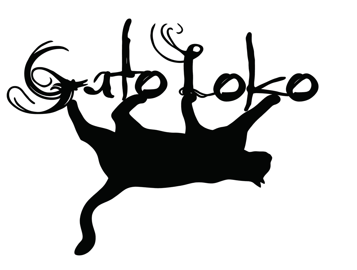
Original GatoLoko band logo used as the base design for the embroidery workflow.
Vector Preparation in Inkscape
The embroidery workflow started with the GatoLoko logo, which is the visual identity of my rock band.
The image was imported into
Inkscape,
where it was converted into vector geometry
using the
Object to Path / Trace Bitmap
workflow.
Vectorization is essential because embroidery machines do not interpret raster images directly. Instead, the geometry must be transformed into mathematical paths that later become stitch trajectories.
For additional details about vectorization workflows, see the documentation from Week 02.
Embroidery Canvas Preparation
After vectorization, the document size inside Inkscape was adjusted to match the embroidery area supported by the Brother machine.
This step is important because embroidery machines operate within fixed physical boundaries determined by the embroidery frame size.
Correctly configuring the workspace dimensions helps avoid:
- Out-of-bound stitching
- Scaling distortions
- Misaligned embroidery paths
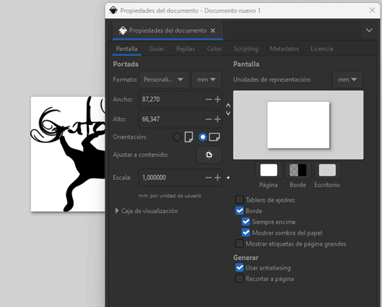
Embroidery workspace configuration adjusted to match the Brother embroidery frame dimensions.
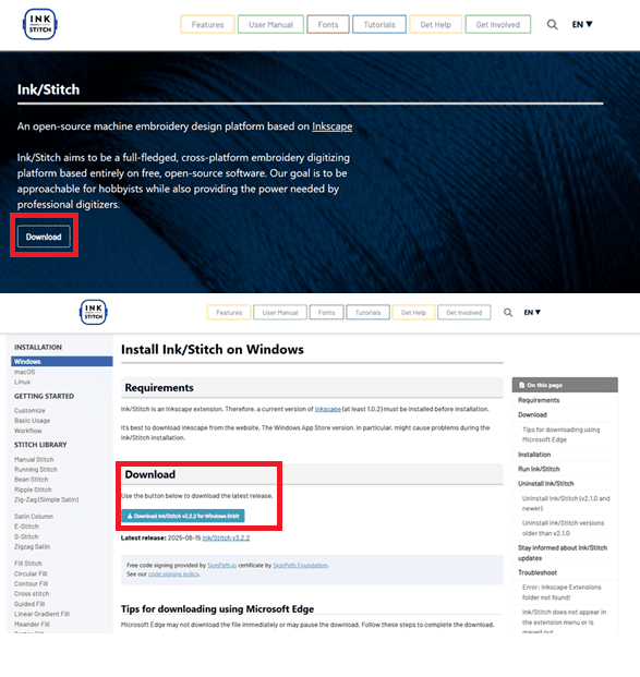
Downloading the Ink/Stitch extension from the official website.
Installing the Ink/Stitch Extension
To convert vector graphics into embroidery instructions, the Ink/Stitch extension was installed inside Inkscape.
Ink/Stitch is an open-source embroidery toolkit that transforms vector paths into stitch patterns, thread trajectories, and embroidery machine instructions.
The extension can be downloaded directly from the official Ink/Stitch website and installed as an Inkscape extension package.
Ink/Stitch Installation Process
After downloading the extension, the installer was executed to integrate Ink/Stitch into Inkscape.
Once installed,
new embroidery tools become available
inside the
Extensions → Ink/Stitch
menu.
This integration transforms Inkscape from a standard vector editor into a complete embroidery CAM environment.
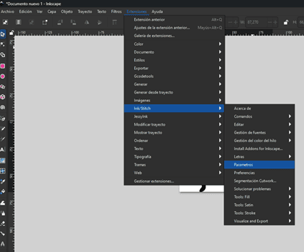
Ink/Stitch installation process for Inkscape integration.
Embroidery Parameters and Simulation
Once the extension was installed, embroidery parameters were configured through:
Extensions → Ink/Stitch → Parameters
Inside this panel, multiple fabrication parameters can be adjusted, including:
- Fill method
- Spacing between stitch rows
- Maximum stitch length
- Thread density
- Stitch direction
- Path optimization
Ink/Stitch also provides a simulation environment that previews the embroidery process before fabrication, allowing stitch validation and reducing fabrication errors.
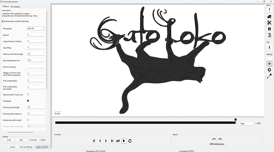
Ink/Stitch parameter configuration, embroidery simulation, and export workflow.
After validating the embroidery simulation,
the final file was exported in
.PES
format,
which is compatible with Brother embroidery machines.
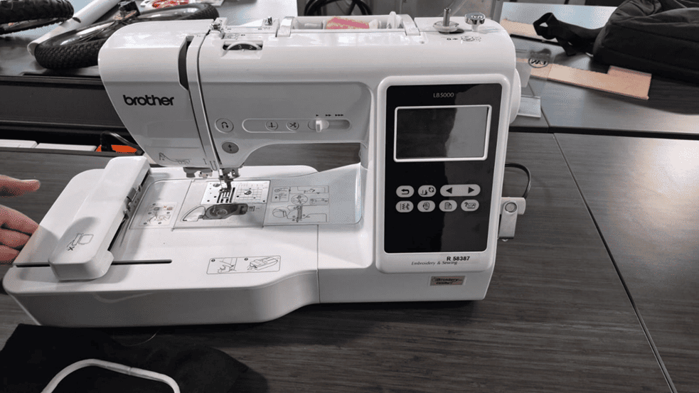
Brother LB5000 embroidery and sewing machine used for the fabrication process.
Brother LB5000 Embroidery Machine
The embroidery was fabricated using the Brother LB5000, a digital sewing and embroidery machine capable of reading embroidery instructions directly from USB storage devices.
The machine supports:
- USB embroidery file loading
- Digital stitch path execution
- Automatic needle positioning
- Adjustable embroidery speed
- Integrated LCD preview interface
The machine interprets the exported
.PES
file and converts it into coordinated motor movements,
controlling needle position
and thread placement automatically.
Material Preparation
Before starting the embroidery process, the fabric was fixed into the embroidery frame to maintain proper tension during stitching.
The selected thread color was mounted in the upper thread path, while a secondary support thread was installed in the lower bobbin system.
Correct thread tension and frame positioning are essential to avoid:
- Thread breakage
- Fabric deformation
- Misaligned stitches
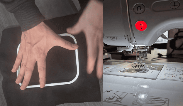
Embroidery frame preparation and thread installation before fabrication.
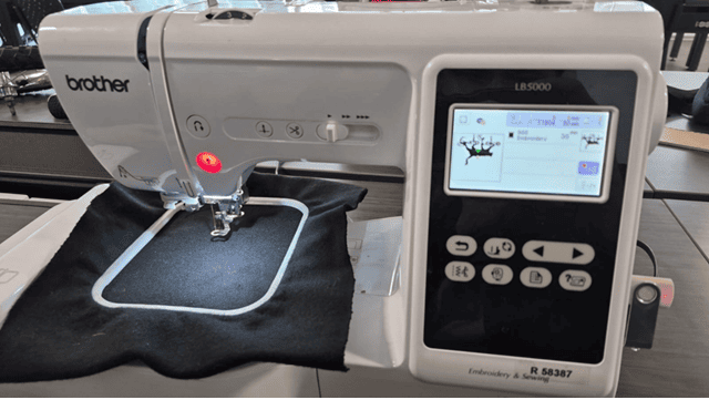
Embroidery file preview displayed directly on the Brother machine interface.
File Loading and Machine Preview
The exported
.PES
file was transferred to a USB memory device
and loaded directly into the embroidery machine.
The Brother interface provides a graphical preview of the embroidery geometry before fabrication, allowing final validation of:
- Scale
- Position
- Stitch area
- Orientation
Embroidery Fabrication Process
Automated embroidery fabrication process executed by the Brother LB5000 machine.
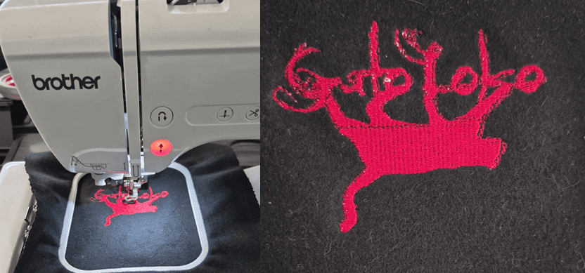
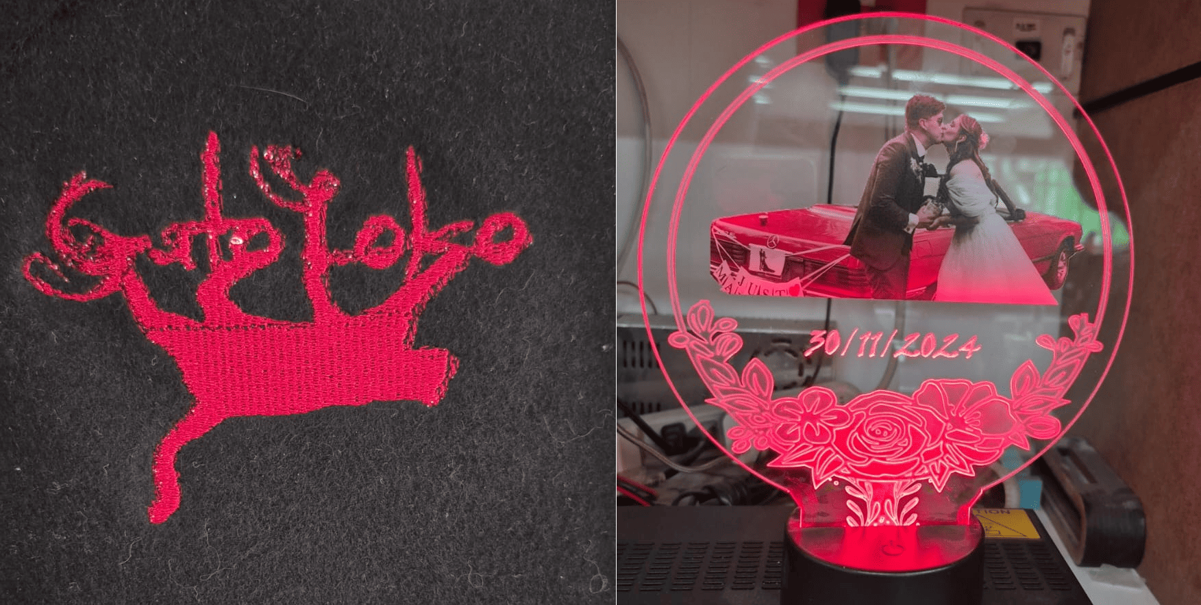
Final embroidered GatoLoko logo fabricated after approximately 20 minutes of machine operation.
Section 2 – UV Printing Workflow
The second fabrication workflow explored during Wildcard Week was UV texture printing on laser-cut acrylic using the EufyMake E1 3D-Texture UV Printer.
For this project, I designed a personalized acrylic lamp using a wedding photograph as a gift for my wife. The final result combines:
- Laser-cut acrylic fabrication
- UV texture printing
- Photographic surface printing
- Edge-lit acrylic illumination
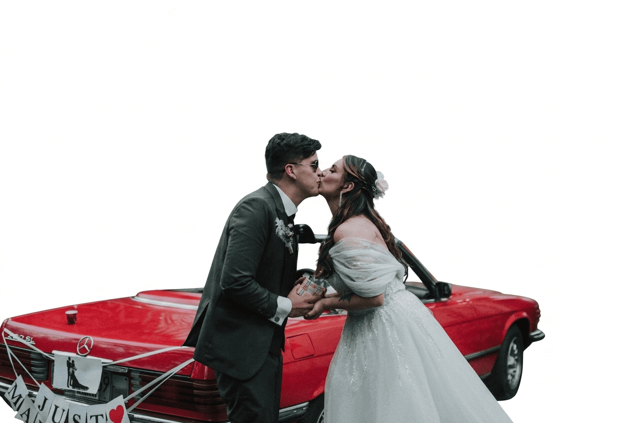
Wedding photograph used for UV printing on laser-cut acrylic.
Acrylic Design and Laser Preparation
The fabrication process started with the design of the acrylic lamp geometry. The structure was created as a 2D vector design intended for laser cutting and engraving.
The vector file was prepared using LightBurn, which allows:
- Vector editing
- Laser path generation
- Power and speed configuration
- Cutting and engraving separation
Since the laser cutting workflow was previously documented during Week 03, this section focuses primarily on the UV printing process.
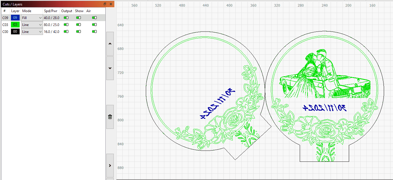
Vector preparation for laser cutting and engraving using LightBurn.
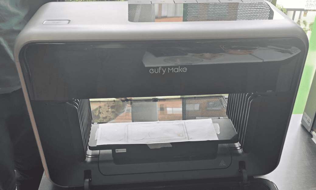
EufyMake E1 3D-Texture UV Printer used for acrylic printing.
EufyMake E1 UV Printer
The printing process was performed using the EufyMake E1, a personal UV printer capable of producing high-resolution textured surface graphics.
Unlike conventional printers, UV printers cure the ink instantly using ultraviolet light, allowing direct printing over rigid materials such as:
- Acrylic
- Glass
- Wood
- Metal
- Leather
One of the most interesting features of the EufyMake E1 is its ability to generate 3D texture printing, creating raised surface effects directly during fabrication.
The machine also integrates:
- Integrated positioning camera
- Automatic material alignment
- Multi-layer ink control
- White + CMYK printing
Material Positioning and Alignment
After laser cutting, the acrylic piece was positioned on the large EufyMake printing base.
The integrated alignment grid was used to manually position the material as accurately as possible before printing.
Proper alignment is critical because:
- The print must match the acrylic geometry
- The image position affects light diffusion
- Misalignment can generate offset printing
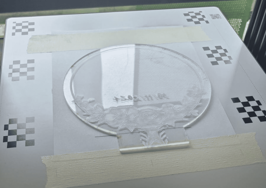
Acrylic positioning and alignment inside the EufyMake E1.
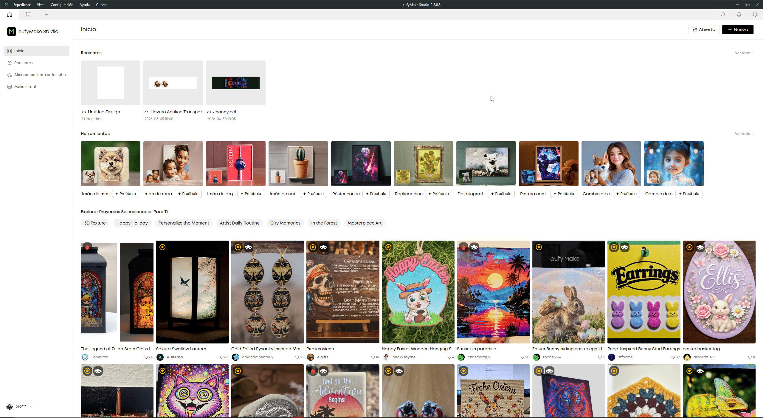
Eufy Studio software interface used for UV print preparation.
Eufy Studio Workflow
The UV printing workflow is controlled through Eufy Studio, the proprietary software platform used to prepare and manage print jobs.
Inside the software, multiple operations can be performed:
- Importing raster and vector graphics
- Background removal
- Texture generation
- Print positioning
- Layer configuration
- Material alignment
The software also includes preconfigured examples and templates for different fabrication workflows, simplifying rapid experimentation.
Camera-Based Print Positioning
Before printing, the background of the wedding photograph was removed, leaving only the main subjects.
The integrated camera of the EufyMake E1 was then activated to visualize the real material surface directly inside the software.
This camera-based workflow allows:
- Real-time positioning preview
- Accurate print alignment
- Direct adjustment over the acrylic
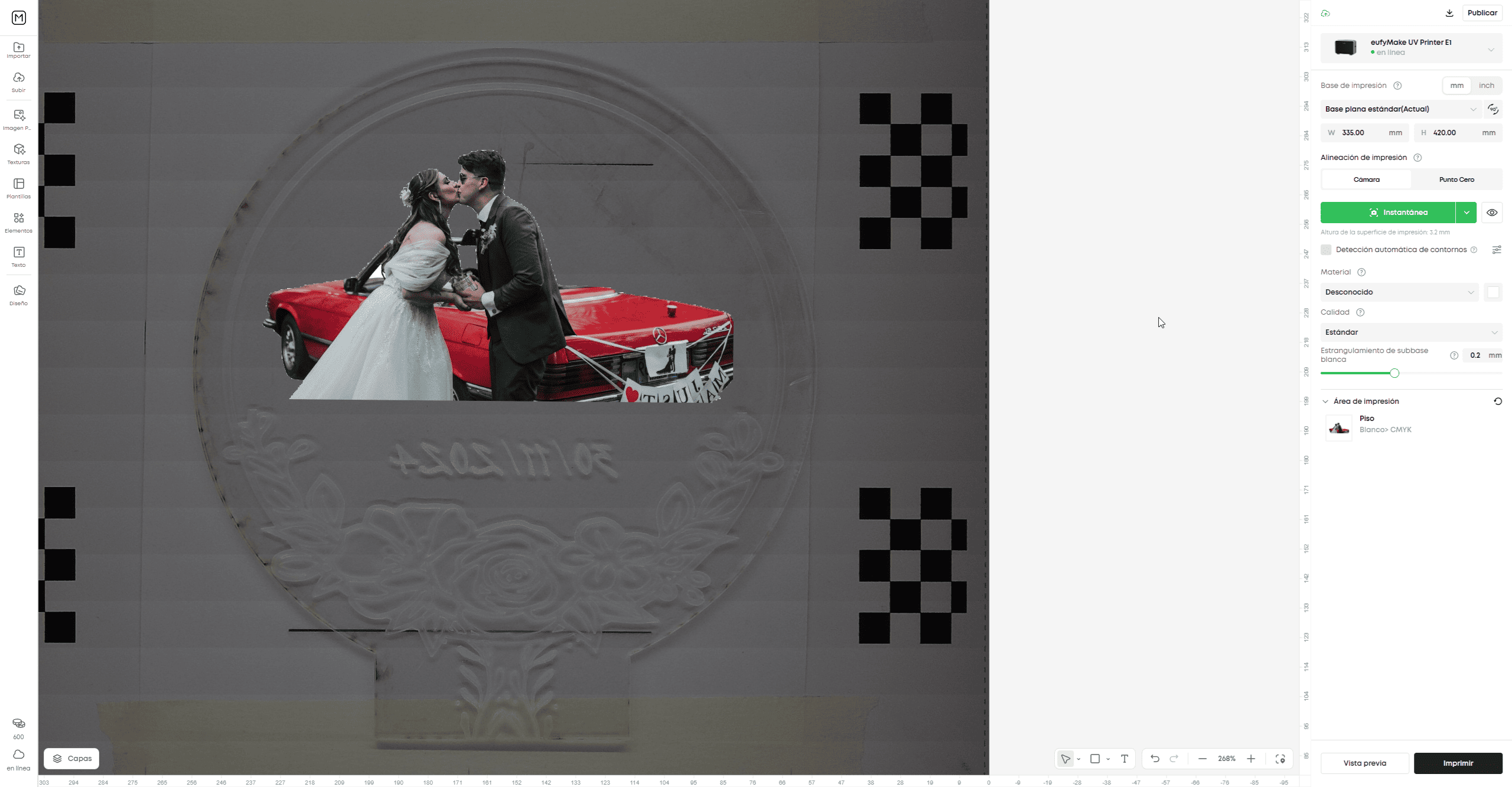
Real-time camera alignment and print positioning inside Eufy Studio.
UV printing parameter configuration inside Eufy Studio.
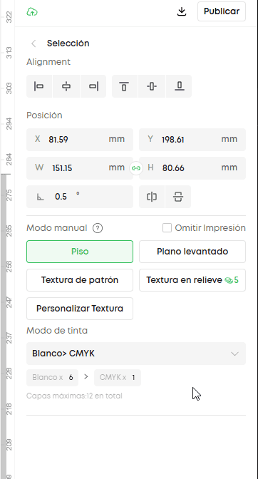
UV Printing Parameters
Before fabrication, several printing parameters were configured inside Eufy Studio.
These parameters directly affect:
- Print quality
- Texture generation
- Ink density
- Material adhesion
Some of the configured parameters include:
- Alignment: print positioning on the material
- Manual Mode: flat or elevated printing mode
- Texture Mode: standard or relief texture printing
- Ink Mode: white + CMYK printing layers
- Maximum Layers: controls texture thickness
These settings determine how the UV printer deposits and cures the ink over the acrylic surface.
UV Printing Process
After sending the project to the printer, the fabrication process starts directly from the machine by pressing the Start button.
During printing, the EufyMake E1 deposits multiple UV ink layers while curing them instantly with ultraviolet light.
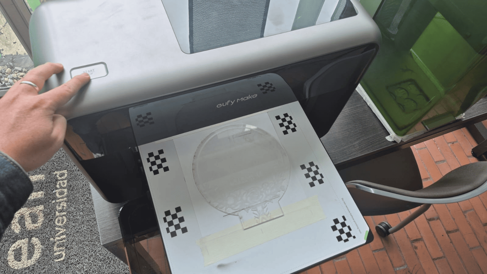
UV printing process executed by the EufyMake E1.
UV texture printing process in real time.
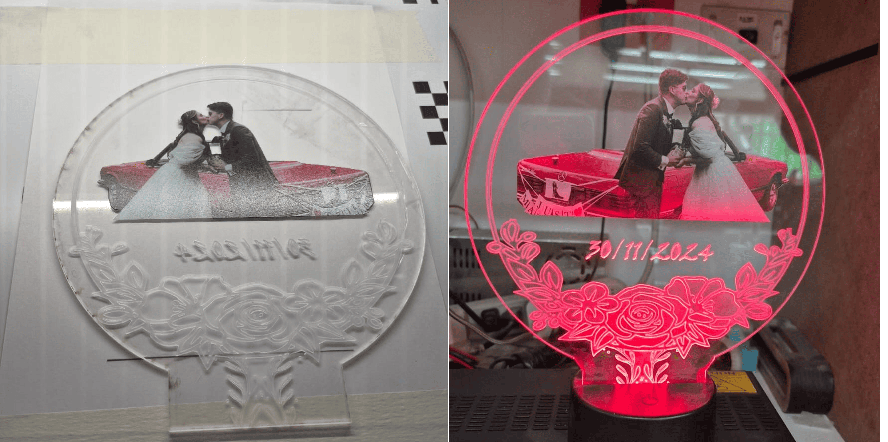
Final illuminated acrylic lamp fabricated using laser cutting and UV texture printing technology.
Final Reflection
Wildcard Week provided an opportunity to explore digital fabrication technologies that differ significantly from the workflows commonly used during Fab Academy. Unlike previous assignments focused mainly on electronics, embedded systems, or subtractive manufacturing, this week emphasized creative fabrication processes involving textile production, surface printing, and hybrid material workflows.
One of the most interesting aspects of this assignment was realizing how different fabrication technologies can share the same digital design foundation. Both embroidery and UV printing started from vector-based workflows, where digital geometry is transformed into machine instructions through specialized CAM processes.
The embroidery workflow introduced a completely different way of thinking about digital manufacturing. Instead of generating toolpaths for cutting or milling, the process converts vector geometry into stitch trajectories, thread density patterns, and sequential needle movements. This highlighted how fabrication logic changes depending on the physical behavior of the material and machine.
Working with Ink/Stitch and the Brother embroidery machine also reinforced the importance of path optimization, stitch direction, spacing configuration, and material preparation. Small parameter adjustments directly affected the final visual quality of the embroidered design.
The UV printing workflow introduced another fabrication paradigm, where images are deposited directly onto physical surfaces using layered UV-cured inks. The EufyMake E1 demonstrated how modern fabrication systems increasingly combine:
- Computer vision
- Texture generation
- Material alignment
- High-resolution printing
- Digital surface engineering
One particularly interesting feature was the integration of real-time camera positioning inside the printing workflow. This created a more intuitive relationship between the digital design and the physical material, improving alignment precision and reducing fabrication errors.
Combining laser cutting with UV printing also demonstrated how hybrid fabrication workflows can significantly expand design possibilities. The laser cutter generated the structural geometry, while the UV printer added visual and textured surface details, creating a final object that combines both functional and aesthetic fabrication processes.
Beyond the technical aspects, this assignment was personally meaningful because both projects had strong emotional and creative value. The embroidered logo represented the visual identity of my rock band, while the acrylic UV-printed lamp became a personalized gift created for my wife.
Overall, this week reinforced the idea that digital fabrication is not limited to mechanical or electronic systems. Modern fabrication workflows increasingly integrate art, personalization, materials engineering, computer-aided design, and digital manufacturing into unified creative processes.
Downloads & Resources
This section provides access to the design resources and downloadable files created during the Wildcard Week assignment. The repository includes vector graphics, embroidery machine files, and laser-cutting designs developed throughout the digital fabrication workflow.
🛠️ Project Resources
The project combines multiple digital fabrication techniques, including vector design, computer-controlled embroidery, laser cutting, and UV printing preparation.
- ✅ SVG Vector Graphics
- ✅ Embroidery Machine Files (.PES)
- ✅ Laser Cutting Designs
- ✅ UV Printing Artwork
- ✅ Fabrication Documentation
- ✅ Project Assets & Supporting Files
📁 Downloadable Files
To improve the loading performance of this documentation website, all project files have been moved to a shared Google Drive folder.
The repository contains the original SVG vector files, embroidery machine files, laser-cutting designs, printable artwork, and supporting documentation developed during Wildcard Week.
Additional fabrication files, design revisions, and updated resources may be added as the project continues to evolve.