Final Presentation
The following media summarize the final outcome of the GameLab Controller. The presentation video demonstrates the complete prototype and its main educational features, while the summary slide provides a concise overview of the project following the Fab Academy final presentation guidelines.
Final demonstration video showing the completed GameLab Controller and its main embedded systems capabilities.
Fab Academy Summary Slide
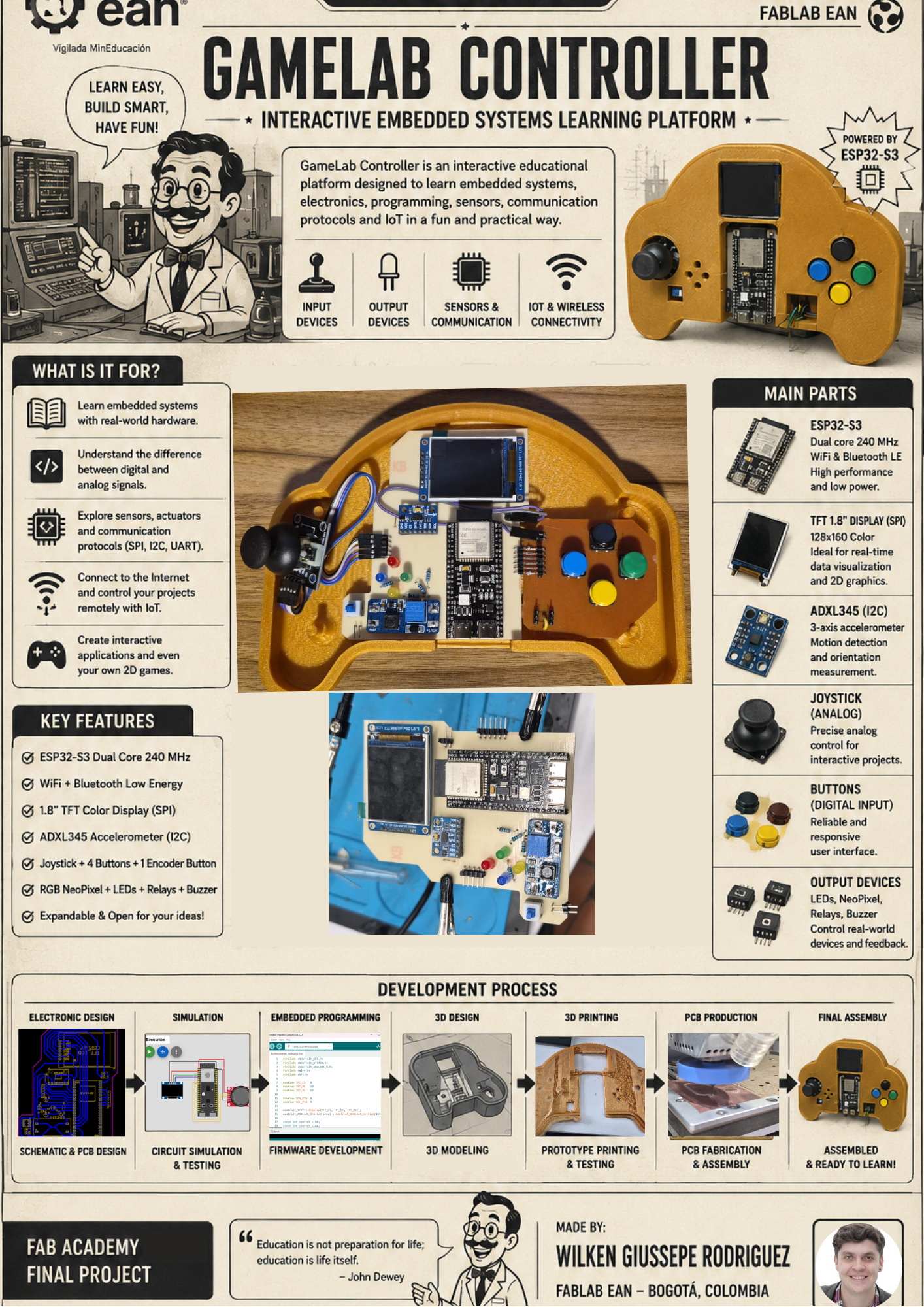
Official presentation slide summarizing the concept, implementation and final outcome of the GameLab Controller.
Project Origin
What is GameLab Controller?
GameLab Controller is a portable educational platform designed to simplify the first steps into embedded systems, robotics and electronics. Instead of requiring students to purchase multiple sensors, displays and electronic modules, the controller integrates the most commonly used peripherals into a single handheld device that is ready for experimentation.
The platform combines an ESP32-S3 microcontroller, a TFT display, joystick, push buttons, LEDs, an IMU sensor and GPIO expansion ports, allowing students to explore programming concepts without spending time assembling temporary breadboard circuits or troubleshooting wiring mistakes.
Educational Objective
The main objective of the project is to provide an accessible learning platform for high school, technical and university students who are beginning their journey into embedded systems. By integrating all the essential hardware into a single device, the controller allows students to focus on programming, experimentation and problem solving rather than hardware assembly.
Motivation
The motivation behind the GameLab Controller came from observing that many students lose interest during their first contact with electronics because they face wiring errors, damaged components and uncertainty about how different modules should be connected. This project aims to remove those initial barriers by providing a robust and reusable educational platform where learning begins immediately after powering on the device.
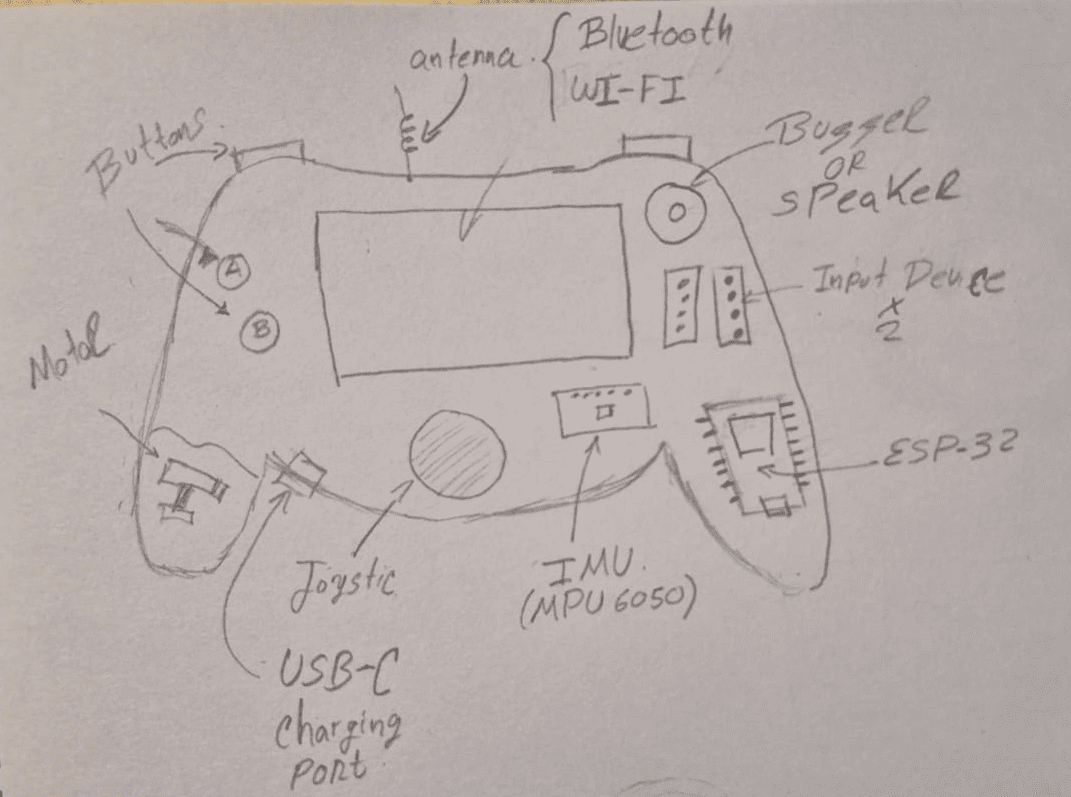
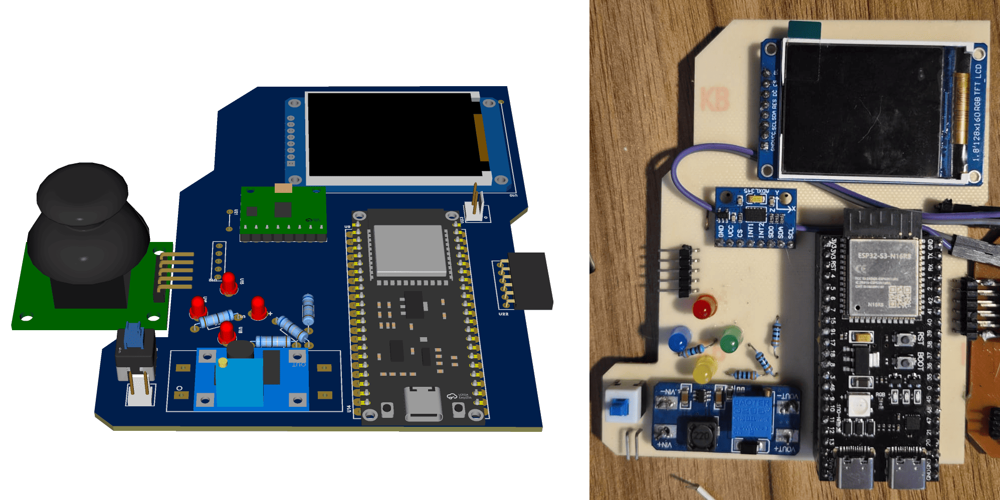
Initial hand-drawn concept used to define the educational objectives, component distribution and overall form factor of the controller.
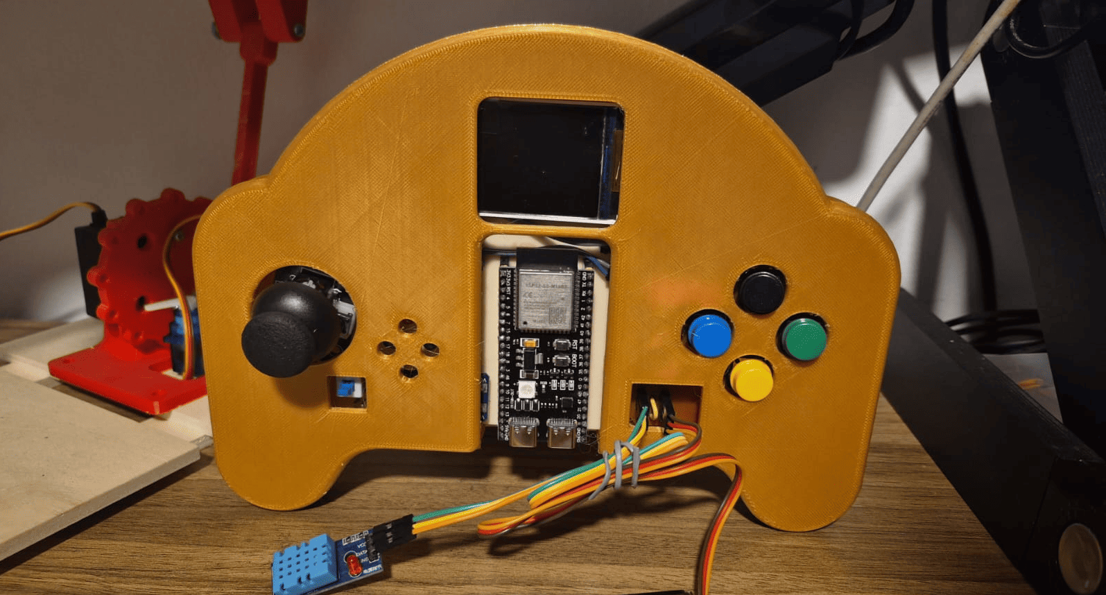
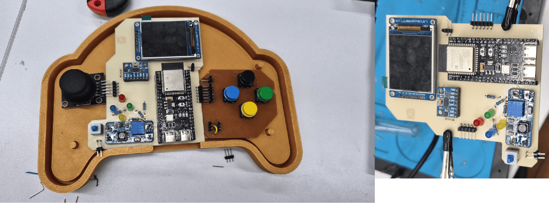
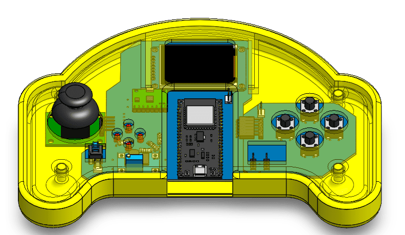
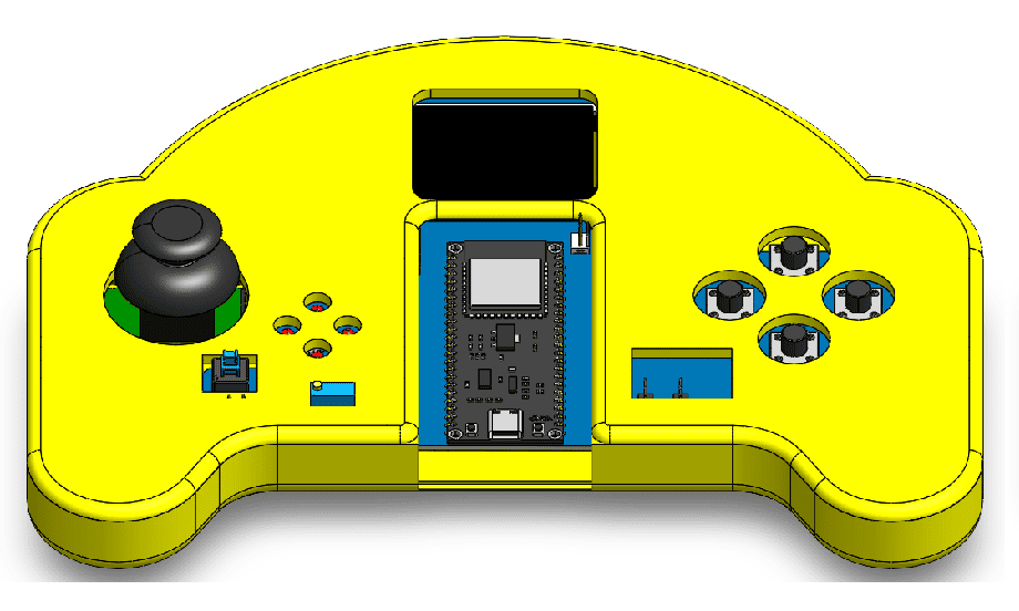
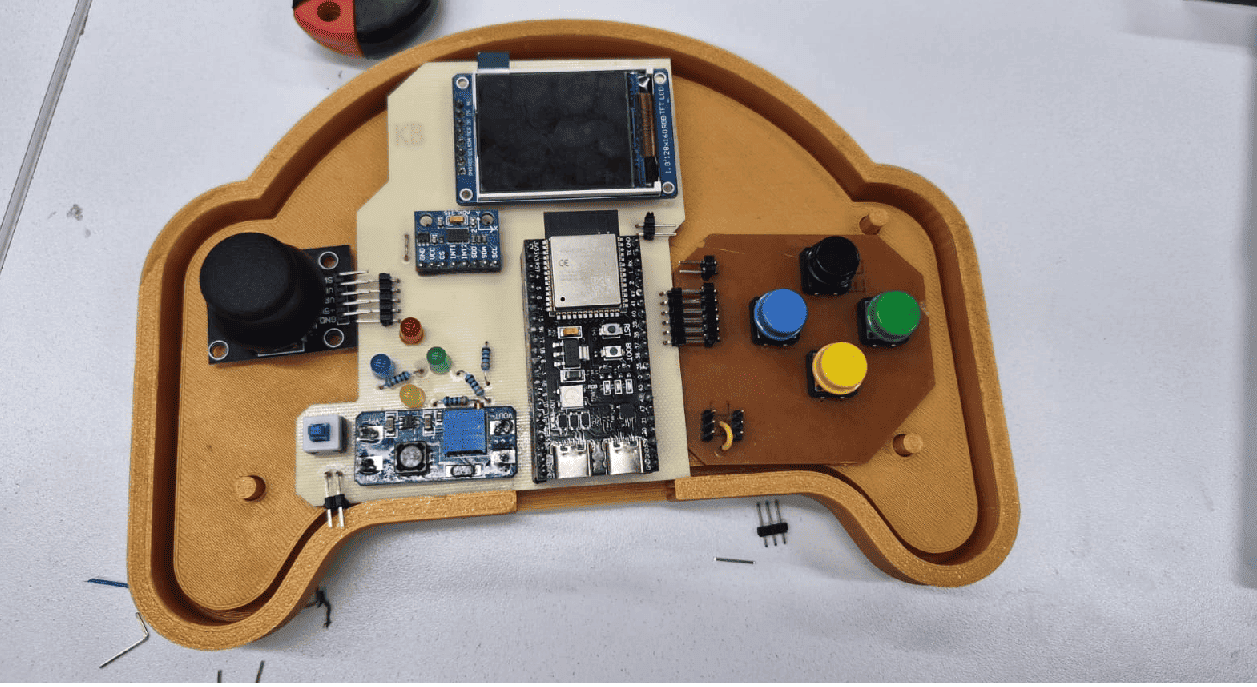
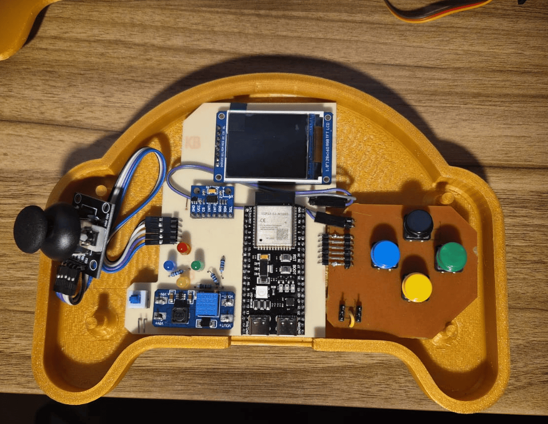
Final prototype after completing the mechanical design, electronics, embedded programming and system integration.
Core Components
The GameLab Controller integrates the most common peripherals used in introductory embedded systems courses into a single handheld platform. Each component was selected to support practical learning activities, allowing students to explore sensing, visualization, user interaction and external hardware expansion without assembling multiple independent electronic modules.
ESP32-S3
Main microcontroller responsible for processing, communication and peripheral control.
1.8" TFT Display
SPI graphical display used for menus, animations and user feedback.
Joystick
Primary navigation input for games, menus and embedded experiments.
4 Push Buttons
Multi-purpose digital inputs for programming exercises and interface control.
ADXL345 IMU
Three-axis accelerometer enabling motion-based interaction and sensor experiments.
4 Status LEDs
Visual indicators for digital outputs and programming activities.
2 GPIO Ports
Expansion connectors for sensors, relays, buzzers, servos and other external devices.
Portable Power
Rechargeable Li-Po battery with charging and boost circuitry for standalone operation.
Design Evolution
The GameLab Controller evolved from an initial hand-drawn idea into a fully integrated educational prototype. The process combined concept design, CAD modeling, electronics development, fabrication, programming and system integration.
The timeline below summarizes the main stages of the project and shows how each design phase contributed to the final result.
Concept
CAD
Electronics
Fabrication
Final Prototype
1. Concept Development
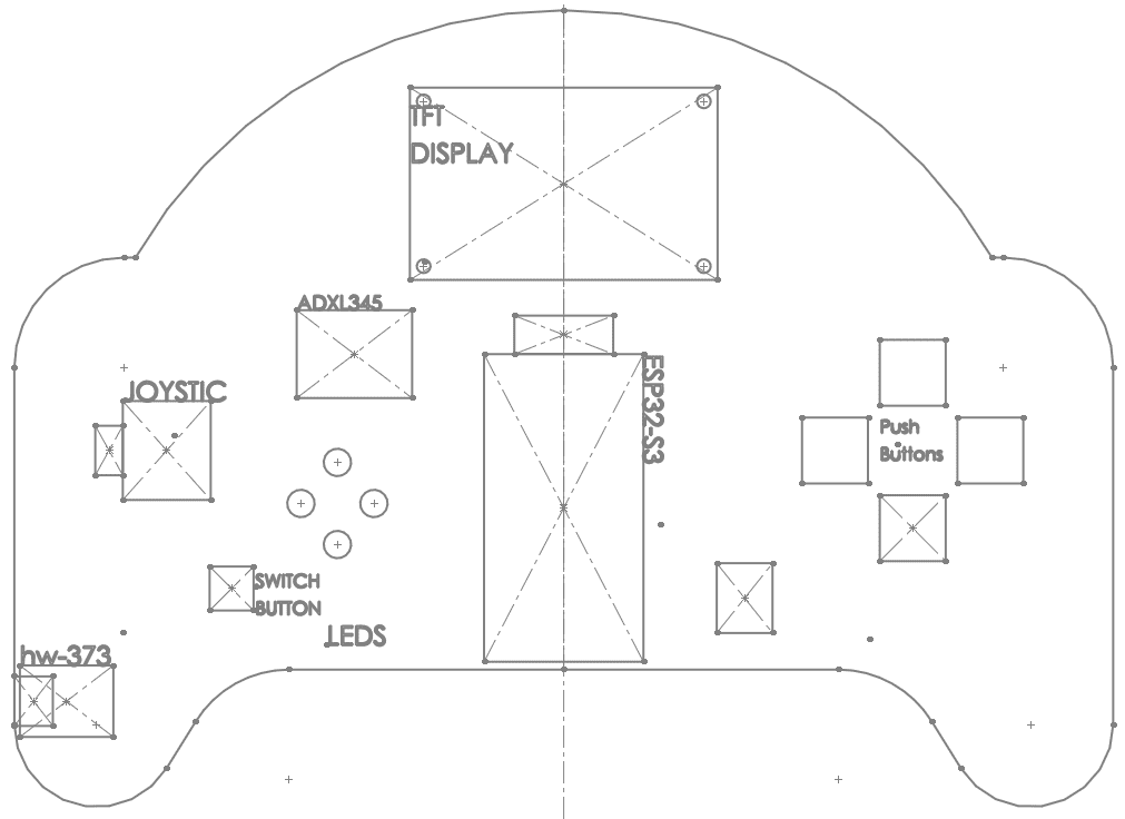
The project began with a hand-drawn sketch used to explore the general shape of the controller, the position of the main interaction elements and the educational purpose of the platform.
This first concept helped define the controller as a handheld embedded systems laboratory rather than a traditional electronics kit.
2. CAD and Mechanical Design
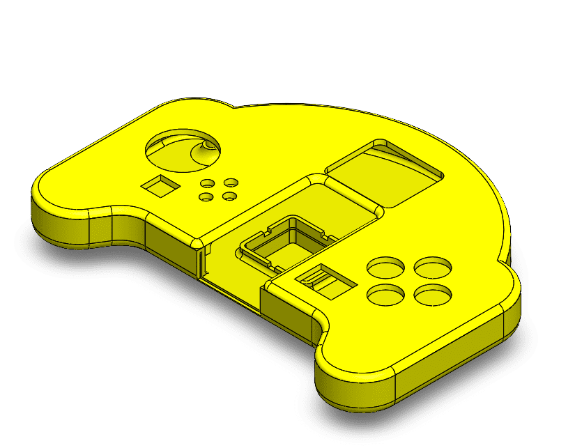
The concept was translated into a 3D model using SolidWorks. The enclosure was designed around ergonomic references from game controllers and expanded to provide enough internal space for the display, PCBs, battery and user interface.
The mechanical design defined the external form factor and the internal organization required for system integration.
3. Electronics Development
The electronics were designed around the ESP32-S3 and distributed across two custom PCBs due to fabrication size constraints. The system includes a TFT display, ADXL345 IMU, joystick, buttons, LEDs and GPIO expansion ports.
This stage transformed the platform from a mechanical concept into an embedded system with sensing, visualization and interaction.
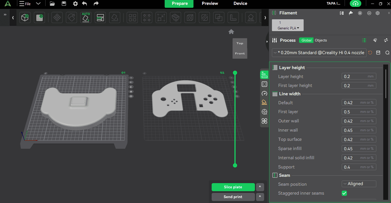
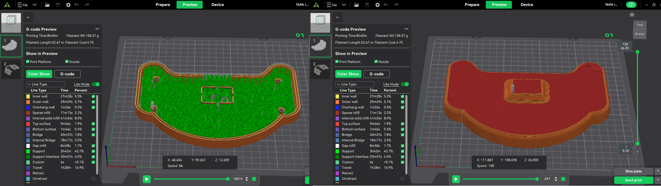
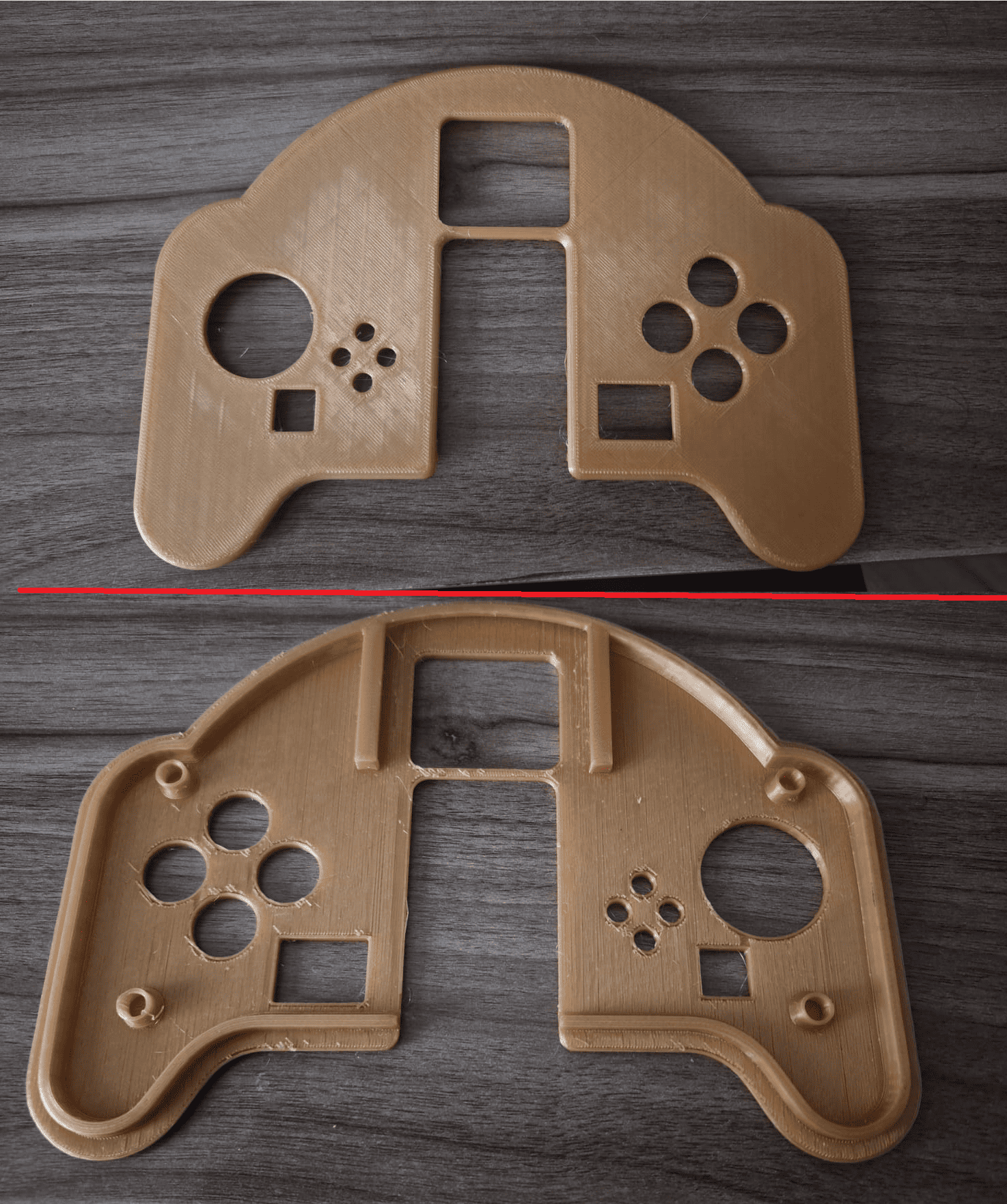
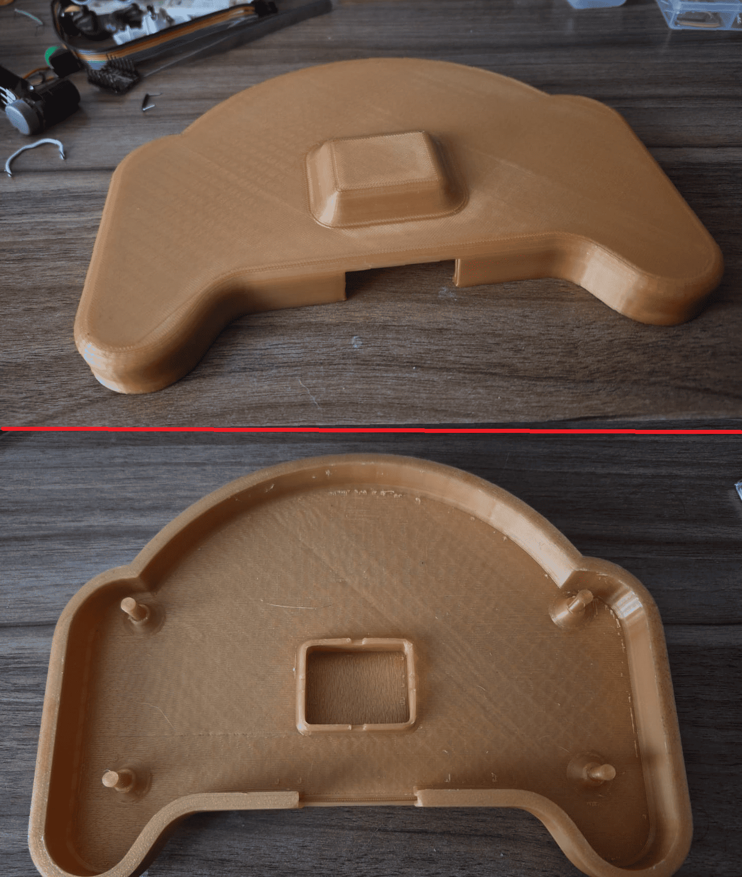
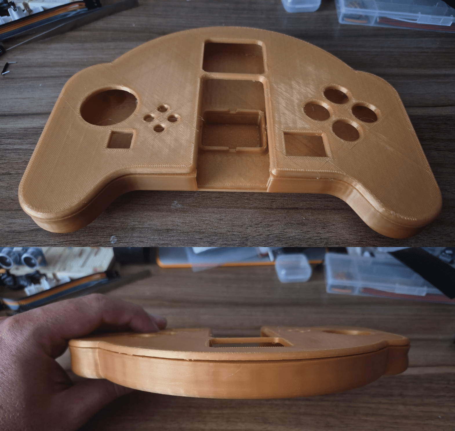
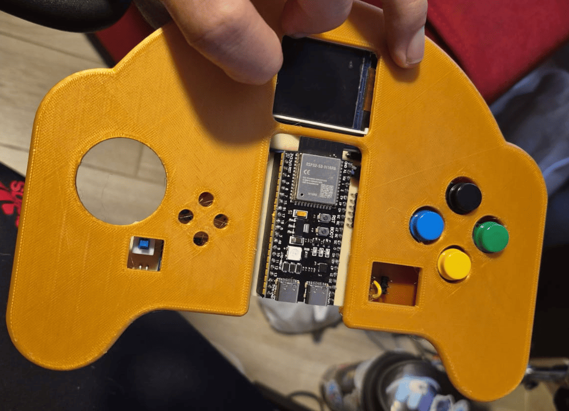
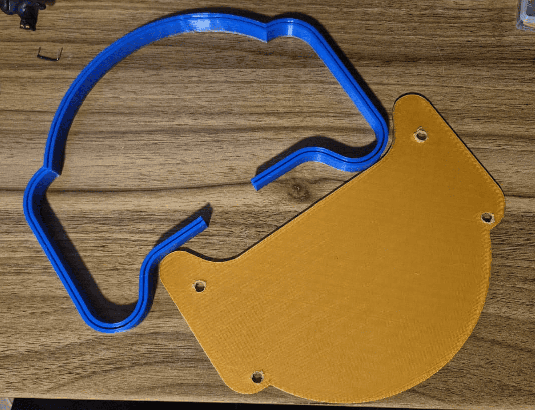
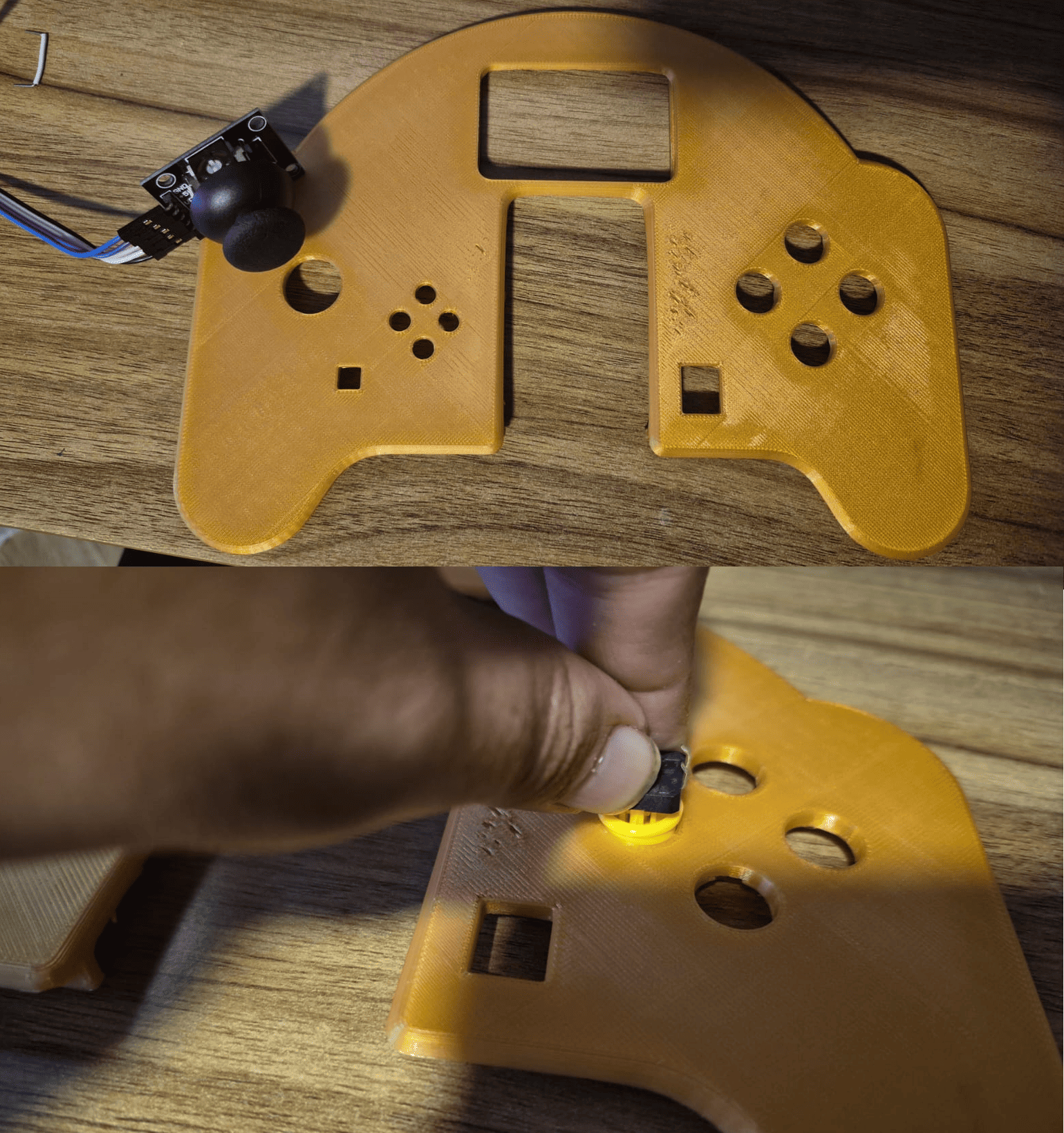
4. Fabrication and Assembly
The enclosure was fabricated using 3D printing, while the custom PCBs were manufactured, soldered and assembled with the commercial modules. The joystick was connected using jumper wires and the two PCBs were interconnected through headers.
This stage validated the physical relationship between the enclosure, electronics and internal packaging strategy.
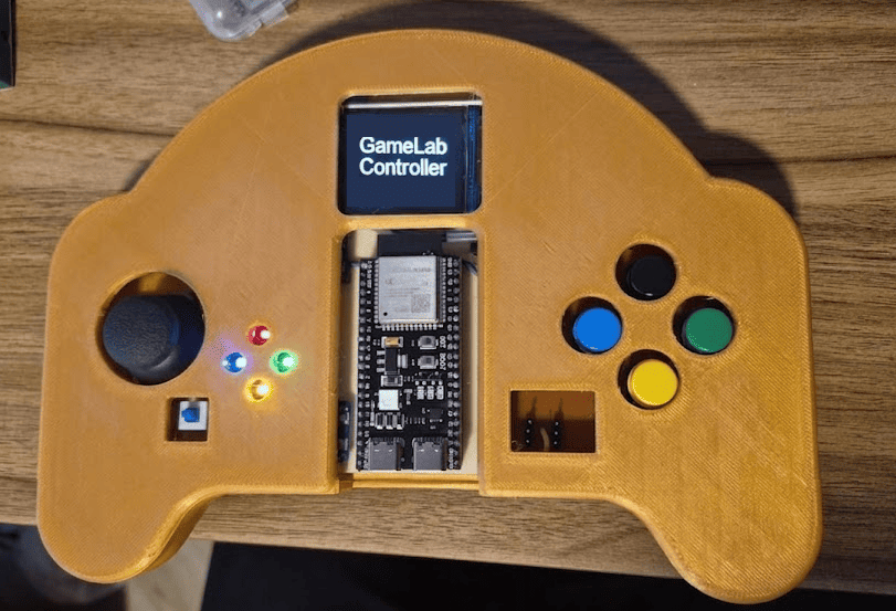
5. Final Prototype
The final prototype integrates mechanical design, custom electronics, embedded programming and educational interaction into a single portable platform.
The result is a functional embedded systems learning device that demonstrates the complete workflow developed throughout Fab Academy.
System Architecture
The GameLab Controller follows a modular architecture where mechanical design, electronics, embedded firmware and expansion interfaces work together as a single educational platform. Instead of functioning as a conventional game controller, the device was conceived as a portable embedded systems laboratory that integrates the most common peripherals used during introductory electronics and programming courses.
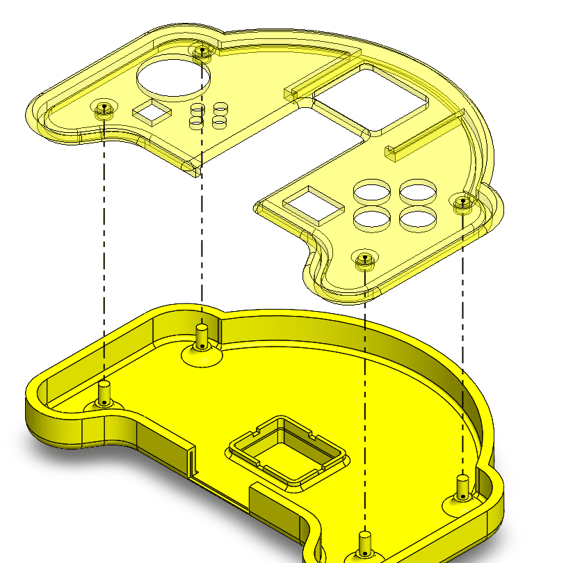
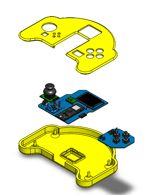
The exploded assembly animation below illustrates how the enclosure, electronic boards and internal modules come together to form the final product. Every component was designed considering accessibility, maintainability and ease of fabrication using Fab Lab equipment.
Exploded assembly animation showing the integration of the enclosure, joystick module, custom PCBs and internal components into the final GameLab Controller.
System Architecture Overview
Mechanical Integration
The enclosure consists of two 3D printed parts designed in SolidWorks. Internal supports, battery compartment and alignment features ensure accurate positioning of the electronics while allowing easy assembly and maintenance.
Electronics Architecture
The system is centered around an ESP32-S3 and distributed across two custom PCBs connected through right-angle headers. The architecture integrates the TFT display, ADXL345 IMU, LEDs, push buttons, power circuitry and GPIO expansion ports.
Embedded Firmware
The firmware manages user interaction, reads sensors, updates the graphical interface and controls external peripherals. The software architecture was developed to support educational demonstrations and future laboratory activities.
Hardware Expansion
Two independent GPIO ports allow external hardware such as sensors, buzzers, relays, servos and motor drivers to be connected. This makes the controller adaptable to a wide range of embedded systems experiments.
Functional System Flow
The following diagram summarizes the internal operation of the GameLab Controller. User interactions generated through the joystick, buttons and IMU are processed by the ESP32-S3, which controls the graphical interface, visual outputs and external GPIO peripherals. This architecture transforms the controller into a complete embedded systems learning platform where students can experiment with inputs, outputs, sensing and hardware expansion.
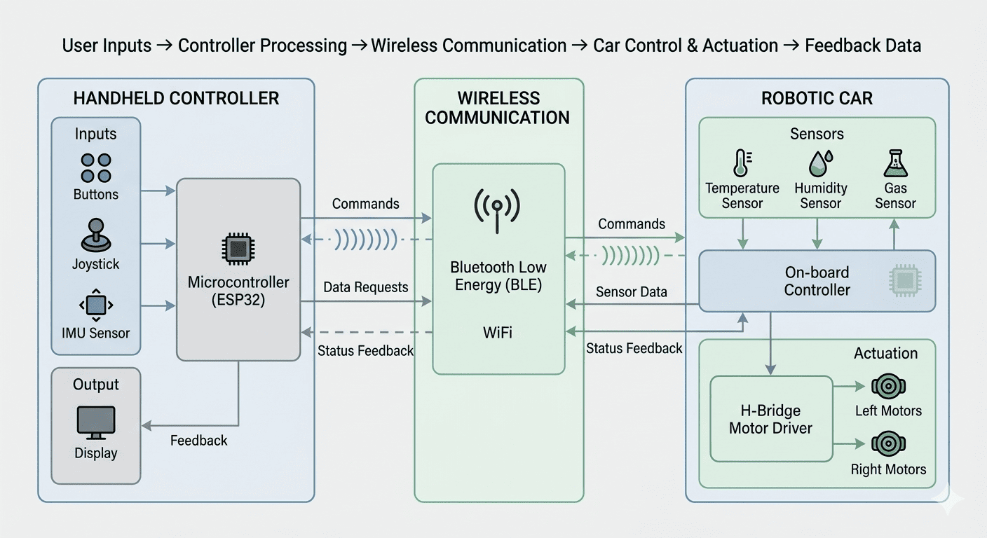
System architecture illustrating the relationship between user inputs, embedded processing, integrated peripherals and educational applications.
Design Choices
The GameLab Controller was developed through a series of design decisions that balanced educational purpose, fabrication constraints, component availability and system integration. Each choice was made to support the main goal of the project: creating a portable and accessible embedded systems learning platform.
Why ESP32-S3?
The ESP32-S3 was selected as the main microcontroller because it provides enough GPIO pins, processing capability and communication options for an educational embedded platform. It also allows the system to support future wireless and IoT learning activities.
Why a Handheld Controller?
A game-controller form factor makes the platform familiar and approachable for students. This shape also supports intuitive interaction with joystick, buttons and display while keeping the device portable.
Why Two PCBs?
Due to Fab Lab fabrication constraints and available copper board sizes, the electronics were divided into two smaller PCBs. This decision made fabrication possible while keeping the layout organized and allowing a clear separation between the main processing board and the button/GPIO interface board.
Why Integrated Peripherals?
The project integrates the most common learning peripherals so beginners can start programming immediately without building circuits from scratch. This reduces wiring mistakes and lets students focus on embedded systems concepts.
Why ADXL345 IMU?
The ADXL345 module was selected to introduce motion-based interaction through I2C communication. It adds sensing capabilities without requiring complex wiring and enables activities related to movement, orientation and sensor data.
Why GPIO Expansion Ports?
The two GPIO ports allow the controller to grow beyond its built-in components. Students can connect sensors, relays, buzzers, servos, motors or other modules, making the device useful for future experiments and classroom challenges.
Tools and Knowledge Used
The development process combined documentation, software tools and Fab Academy knowledge. Datasheets and technical references were used to verify electrical compatibility, while SolidWorks, EasyEDA and Arduino IDE were used to transform the concept into a functional prototype.
SolidWorks
Used for 3D modeling, enclosure design and assembly validation.
EasyEDA
Used for schematic capture, PCB routing and electronic design.
Arduino IDE
Used for ESP32-S3 firmware development and peripheral testing.
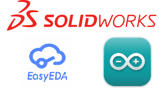
Main software tools used during mechanical design, electronics design and embedded programming.
Fab Academy Skills Integrated
The final design was not developed as an isolated product. It was the result of multiple Fab Academy assignments combined into one complete system.
Development Journey
Phase 0 · Planning, Timeline and Budget
Before fabrication started, the GameLab Controller was planned as an incremental project. This phase defined the expected workflow, the main development stages, the materials required and the estimated cost of the prototype. The goal was to reduce technical risk by organizing the project before moving into CAD design, electronics fabrication and system integration.
The planning stage helped define the order of work: first the concept and architecture, then the mechanical design, PCB design, fabrication, programming, integration, testing and final documentation.
Planned Development Phases
| Phase | Expected Activities |
|---|---|
| Concept Development | Define educational objectives, system requirements, user interaction model and overall architecture. |
| Mechanical Design | Create CAD models, evaluate ergonomics, define internal component placement and prepare files for fabrication. |
| Electronics Design | Develop schematics, select components and design custom PCBs for the embedded platform. |
| Fabrication | Manufacture PCBs, print enclosure components and prepare all mechanical and electronic parts. |
| Programming | Develop firmware for the ESP32-S3, including display management, input processing and sensor communication. |
| System Integration | Assemble all subsystems, validate mechanical fit and verify electrical connections. |
| Testing & Optimization | Evaluate performance, solve integration issues and improve user experience. |
| Documentation & Presentation | Produce final documentation, presentation assets, demonstration video and project summary. |
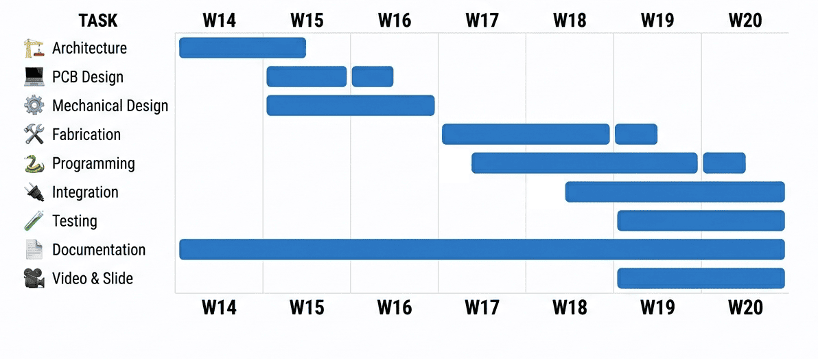
Planned roadmap describing the expected development stages of the GameLab Controller from concept definition to final delivery.
Materials and Cost Overview
The bill of materials was prepared during the planning stage to estimate the cost of the prototype and identify which parts would be fabricated in the Fab Lab and which components would be purchased as commercial modules.
| Item | Qty | Estimated Cost | Source / Purchase Link |
|---|---|---|---|
| ESP32-S3 Development Board | 1 | $11.99 USD | Purchase link |
| 1.8" 128×160 RGB TFT Display | 1 | $9.99 USD | Purchase link |
| ADXL345 IMU Module | 1 | $7.29 USD | Purchase link |
| Analog Joystick Module | 1 | $8.80 USD | Purchase link |
| Push Buttons | 4 | $6.99 USD | Purchase link |
| KIT LEDs | 4 | $7.99 USD | Purchase link |
| KIT HEADERS | 1 | $9.99 USD | Purchase link |
| Li-Po Battery 3.7V 500mAh | 1 | $8.69 USD | Purchase link |
| HW-373 Charging Module | 1 | $6.99 USD | Purchase link |
| Boost Converter Module | 1 | $5.96 USD | Purchase link |
| KIT FR-1 Copper Board | 2 | $7.99 USD | Purchase link |
| PLA Filament | ~250 g | $14.44 USD | Fab Lab inventory |
| Total Estimated Cost | $107.11 USD |
This planning phase established a clear development path and confirmed that the project was feasible using available Fab Lab processes, including PCB fabrication, 3D printing and embedded programming. It also provided a realistic budget for the first functional prototype.
Phase 1 · Mechanical Design & Prototyping
Once the project objectives and development plan were established, the next step was transforming the initial concept into a manufacturable mechanical design. This phase focused on creating an ergonomic enclosure capable of integrating every electronic subsystem while remaining compact, portable and easy to assemble.
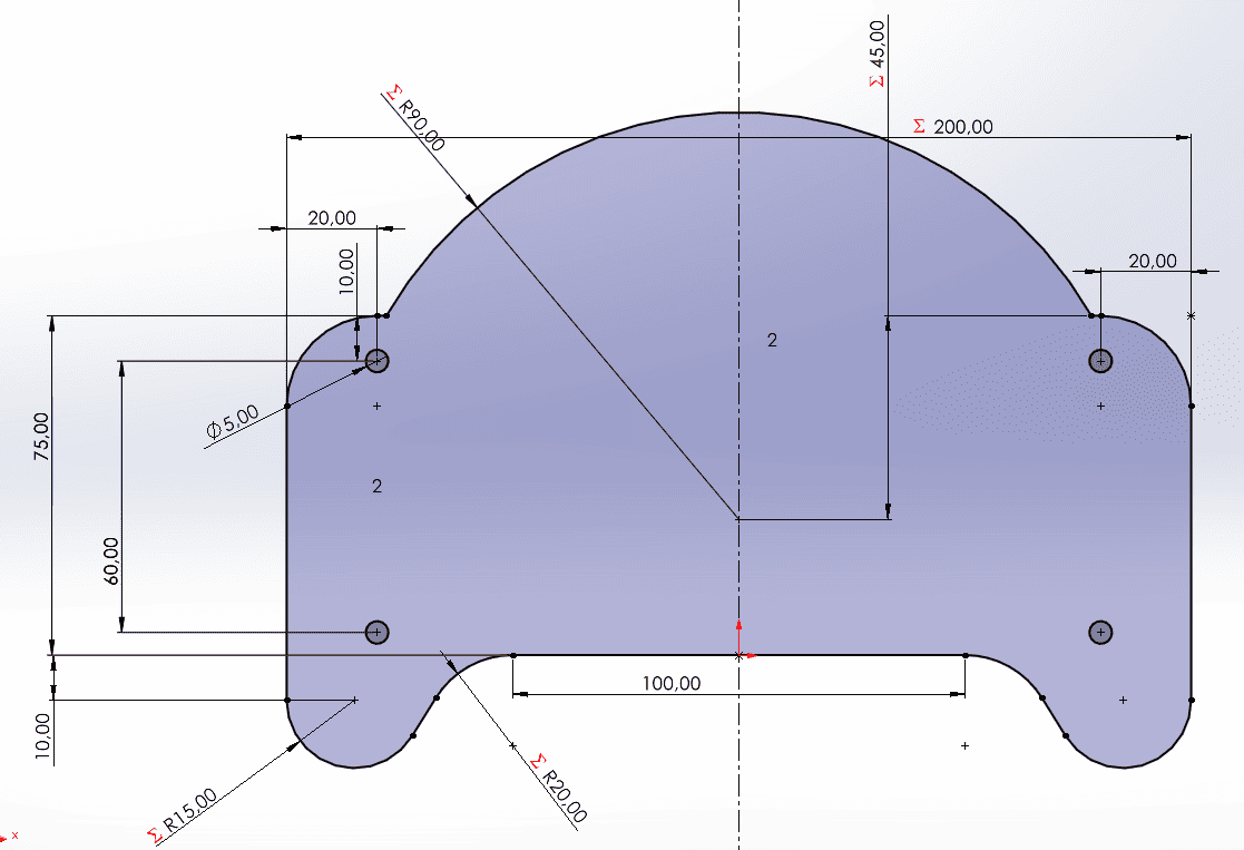
The enclosure was completely modeled in SolidWorks following an iterative design process. Standard game controllers served as ergonomic references, while the internal geometry was adapted to accommodate the ESP32-S3, TFT display, battery, joystick, custom PCBs and expansion connectors.
CAD model of the GameLab Controller developed in SolidWorks before fabrication.
Design Objectives
- Create an ergonomic handheld controller.
- Provide enough space for all electronic modules.
- Allow simple assembly and maintenance.
- Protect the electronics during classroom use.
- Support future hardware upgrades.
Mechanical Features
- Two-piece enclosure.
- Dedicated battery compartment.
- Integrated PCB mounting supports.
- Joystick and display alignment.
- Rear access for programming and charging.
CAD Development
The GameLab Controller evolved through multiple design iterations, refining ergonomics, component placement and manufacturability. Each model introduced improvements that progressively transformed the initial concept into the final enclosure prepared for fabrication.
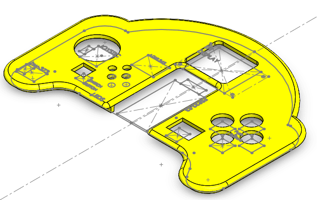
Progressive evolution of the GameLab Controller mechanical design, showing the transition from the first enclosure concept to the final manufacturing- ready assembly.
3D Printing and Assembly
Throughout the modeling process, several iterations were required to improve ergonomics and ensure sufficient internal clearance for the electronic components. The enclosure evolved from a simple concept into a fully manufacturable assembly prepared for additive fabrication.
Phase 2 · Electronics Design & PCB Fabrication
With the mechanical enclosure validated, development continued with the electronic architecture of the GameLab Controller. The objective of this phase was to design a compact embedded platform capable of integrating all the required peripherals while remaining compatible with the internal space defined during the CAD stage.
The complete electronic system was designed in EasyEDA around an ESP32-S3 development board. Besides providing sufficient processing power, the ESP32 offered the GPIO resources required to interface the TFT display, joystick, LEDs, push buttons, IMU sensor and external expansion ports.
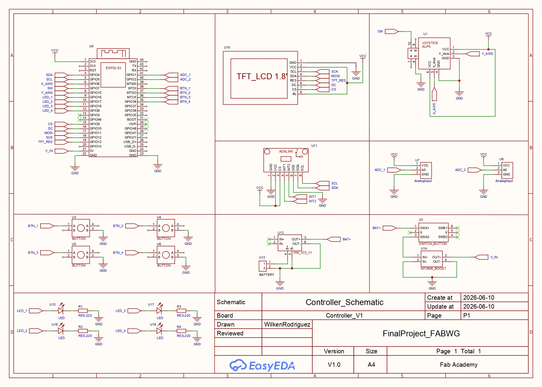
Complete electronic schematic developed in EasyEDA for the GameLab Controller.
Electronics Architecture
- ESP32-S3 as the central controller.
- 1.8" SPI TFT display.
- ADXL345 three-axis accelerometer.
- Analog joystick module.
- Four programmable push buttons.
- Four status LEDs.
- Battery charging and boost circuitry.
- Two GPIO expansion ports.
Engineering Decisions
The initial objective was to manufacture a single PCB; however, the maximum dimensions available for PCB fabrication in the Fab Lab made this impractical. To overcome this limitation, the electronic system was divided into two custom boards interconnected through right-angle headers.
The joystick remained on its commercial module because its compact PCB already provided a robust mechanical structure and simplified assembly inside the enclosure.
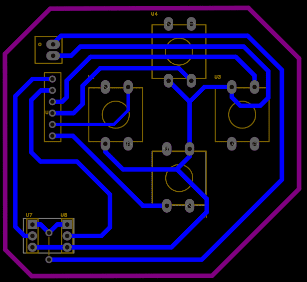
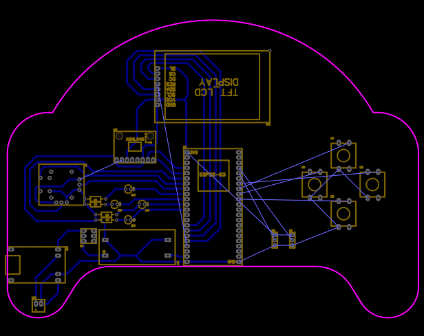
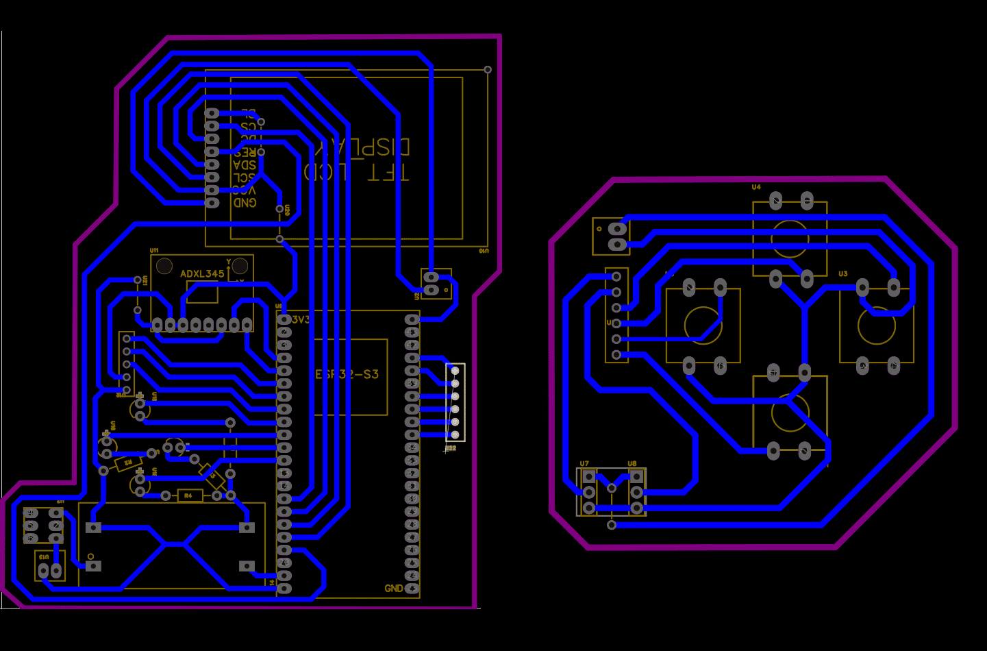
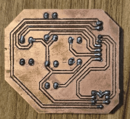
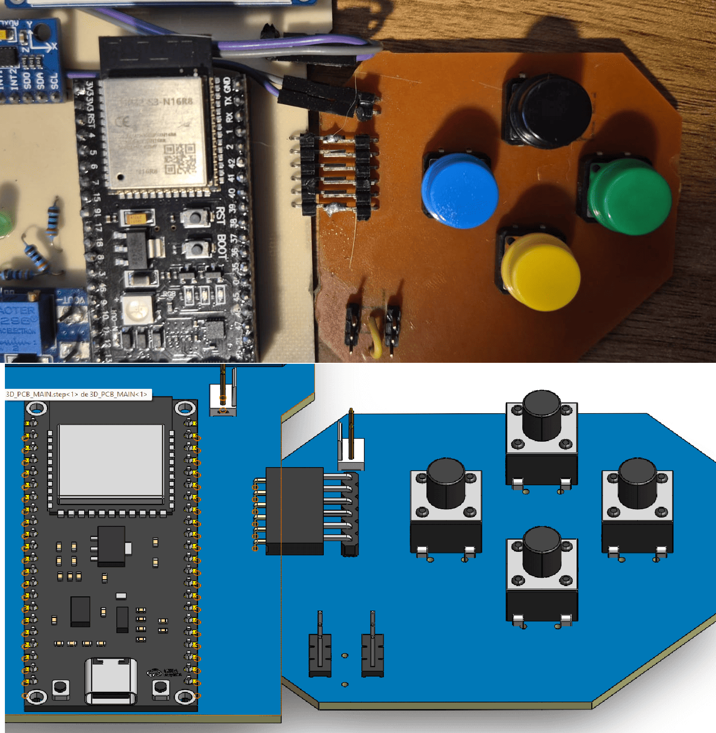
PCB Design
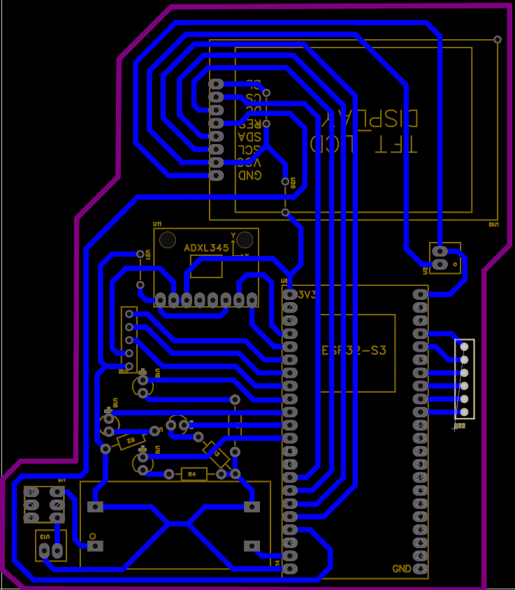
Main PCB integrating the ESP32-S3, display, IMU and power management.
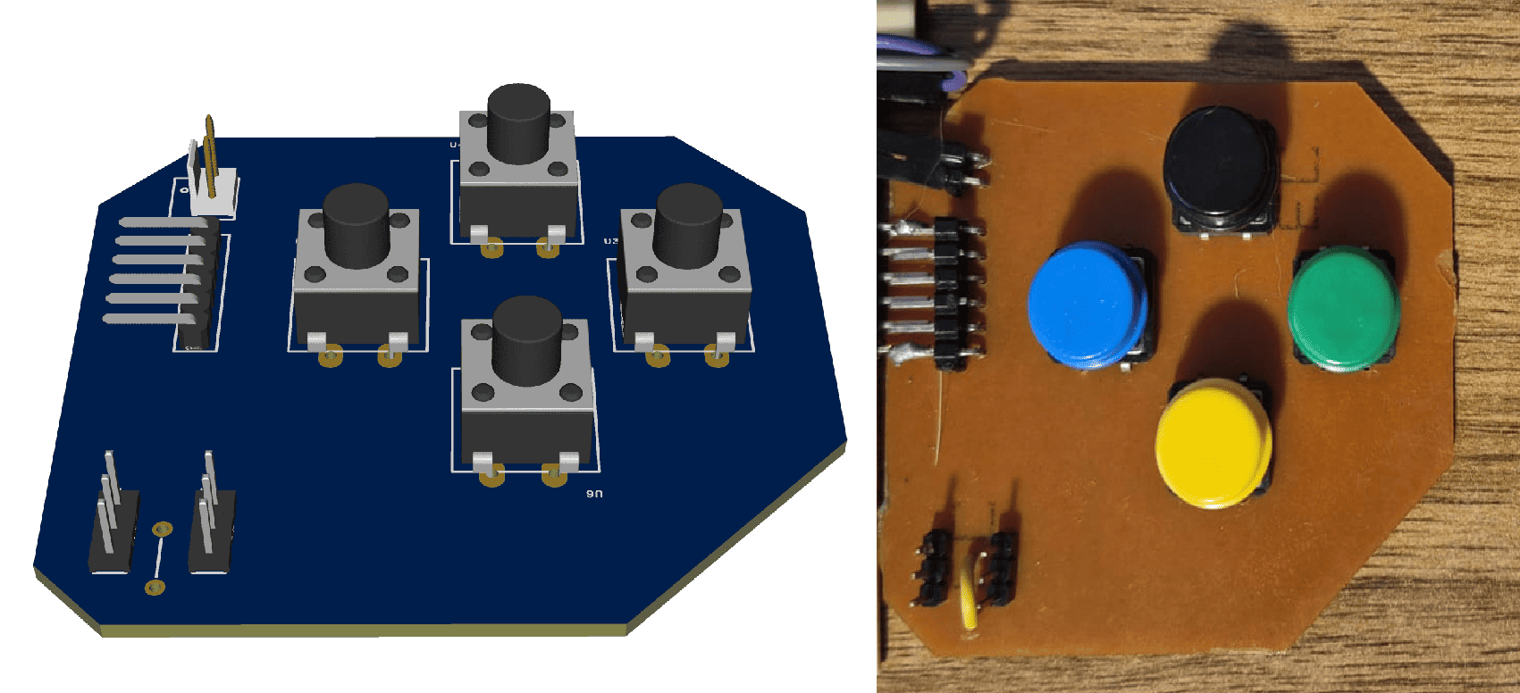
Secondary PCB integrating push buttons and GPIO expansion ports.
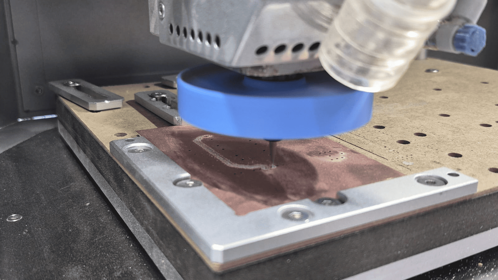
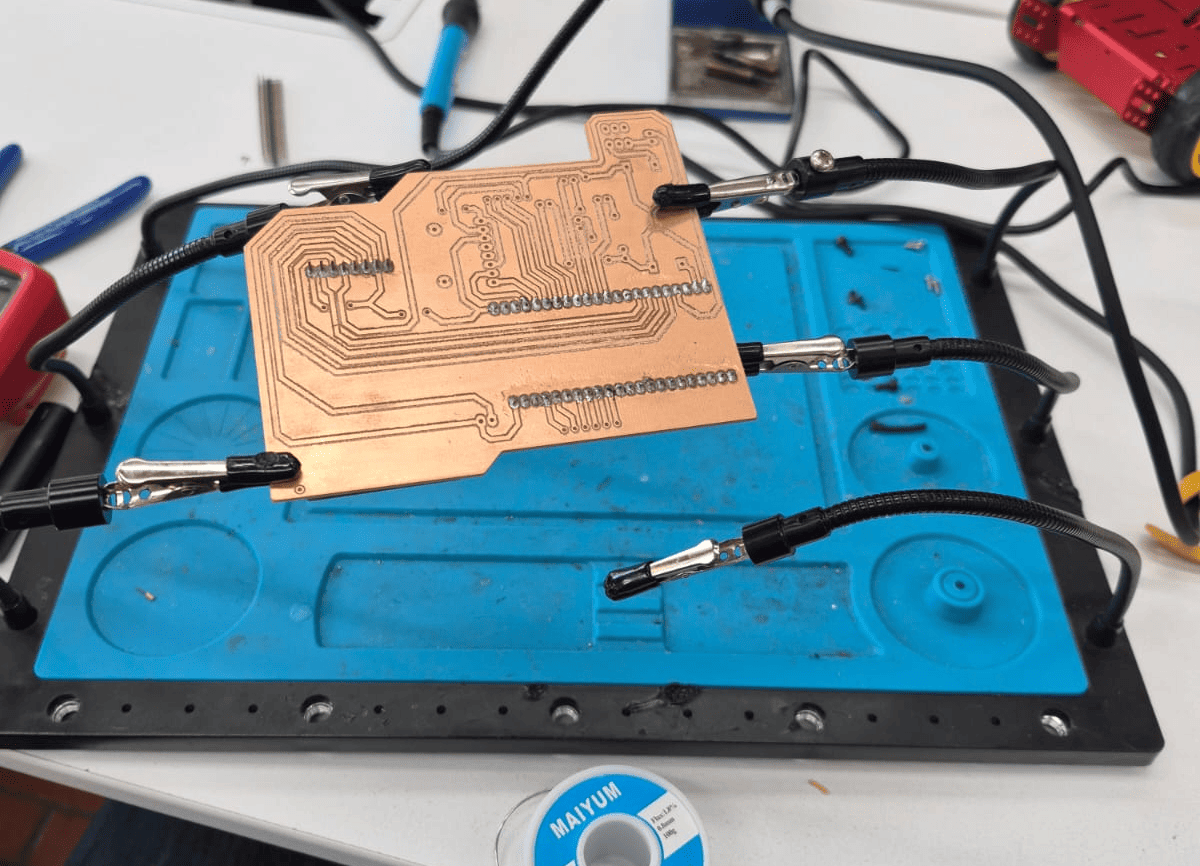
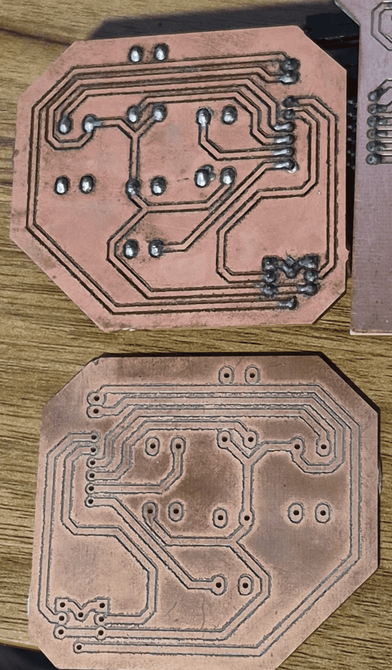
PCB Manufacturing
Both PCBs were fabricated in the Fab Lab using a PCB CNC milling machine and single-sided FR-1 copper boards. After milling, the boards were cleaned, drilled where necessary and manually soldered before electrical validation.
CNC milling process used to manufacture the custom PCBs.
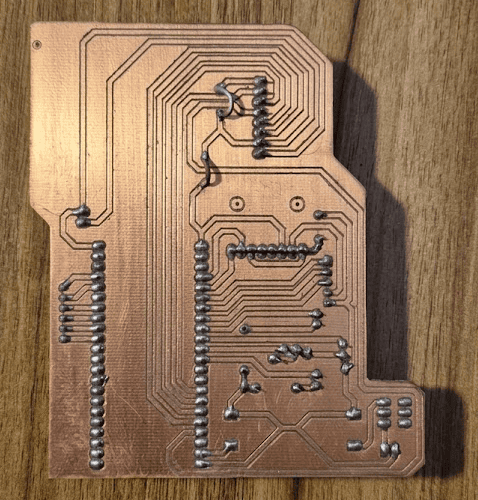
Assembly and Soldering
After fabrication, all electronic components were manually soldered and individually tested before integration. Special attention was given to the display connector, power circuitry and header alignment, ensuring reliable electrical connections throughout the system.
Outcome of Phase 2
By the end of this phase, both custom PCBs had been successfully designed, manufactured and assembled. The electronic platform was electrically validated and ready to be integrated with the 3D printed enclosure during the following system assembly stage.
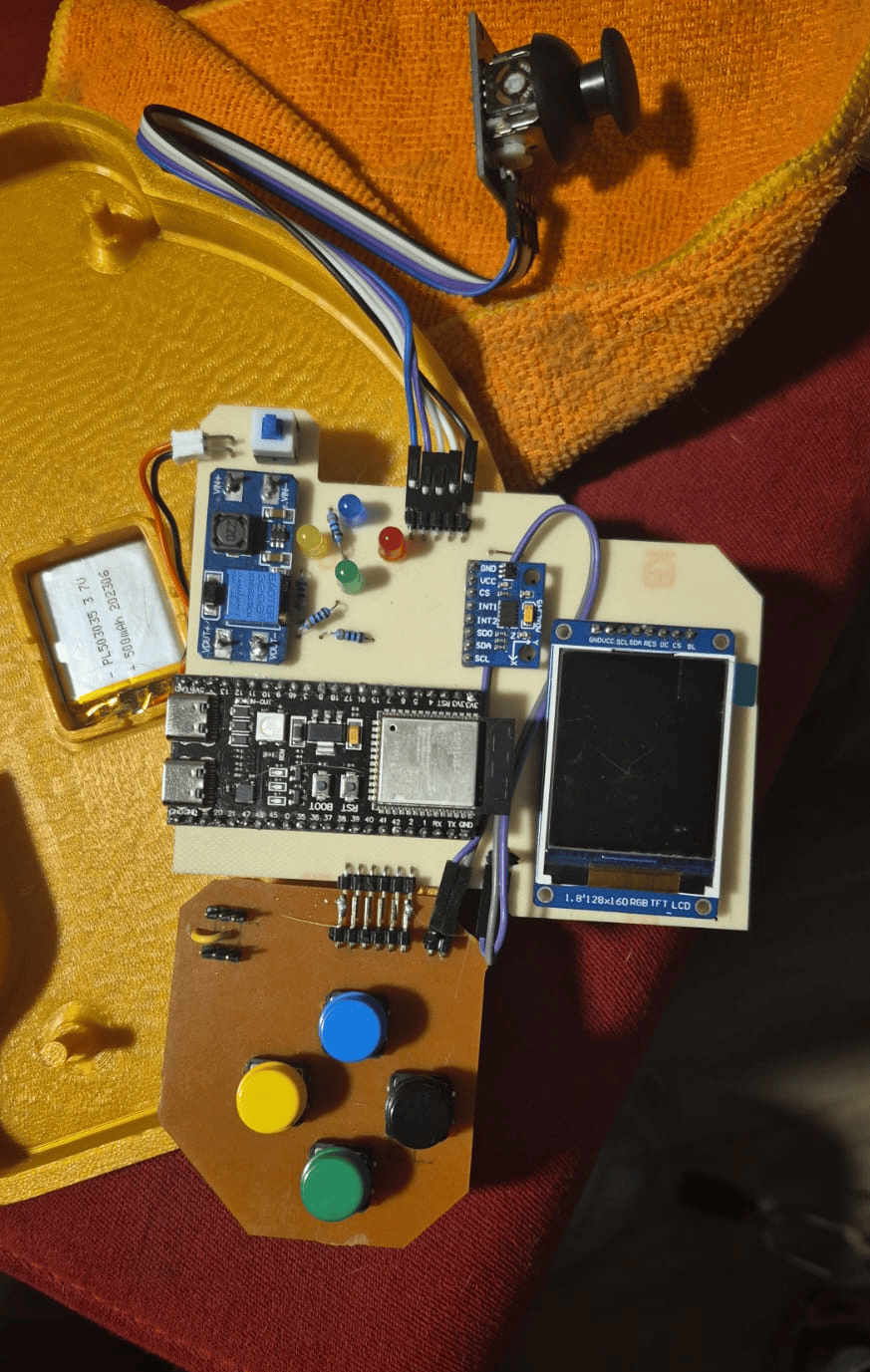
Phase 3 · System Integration & Assembly
After completing the mechanical enclosure and validating both custom PCBs, the next step was integrating every subsystem into a single portable platform. This phase combined mechanical packaging, electrical interconnection and component assembly to transform independent modules into the final GameLab Controller.
Unlike previous stages, where each subsystem was developed independently, system integration required validating the interaction between mechanical, electronic and embedded components simultaneously. Small dimensional errors, connector alignment and cable routing became critical factors that directly influenced the final assembly.
Exploded assembly animation showing how the enclosure, joystick module, battery and both custom PCBs are integrated into the final GameLab Controller.
Mechanical Integration
The enclosure was designed to simplify assembly while maintaining a compact and robust structure. Internal supports positioned the PCBs, battery and display without requiring additional brackets, reducing the number of manufactured parts.
- Two-piece 3D printed enclosure.
- Dedicated battery compartment.
- Internal mounting pillars.
- 3 mm alignment lip between both halves.
- Removable ESP32-S3 access.
Electrical Integration
The electronic system was interconnected using a combination of right-angle headers and jumper wires. This solution minimized the number of cables while allowing every module to remain accessible during debugging and future maintenance.
- 90° headers joining both PCBs.
- Joystick connected through jumper wires.
- Double-sided tape securing the electronics.
- Minimal internal wiring.
- Easy component replacement.
Assembly Process
Packaging Strategy
One of the main objectives of the packaging strategy was keeping the system easy to assemble and maintain. The joystick remained on its commercial PCB, while the remaining electronics were distributed across two custom boards. This arrangement simplified fabrication, reduced wiring complexity and provided enough internal space for future modifications.
Since the ESP32-S3 development board is removable, the controller can also serve as a reusable platform where students may temporarily use the module in other embedded systems projects without permanently modifying the hardware.
Outcome of Phase 3
At the end of this phase, every mechanical and electronic subsystem had been successfully integrated into the enclosure. The GameLab Controller evolved from a collection of independent parts into a complete embedded systems platform ready for firmware validation and functional testing.
Phase 4 · Embedded Programming, Testing & Validation
With the mechanical assembly completed and the electronic hardware fully integrated, the final stage focused on firmware development and functional validation. The objective was to transform the assembled hardware into a complete educational platform capable of demonstrating the interaction between sensors, user interfaces and embedded software.
The firmware was developed using the Arduino IDE for the ESP32-S3, progressively testing each peripheral before integrating them into a single application. Every hardware module was validated independently and later combined into a unified embedded system capable of supporting future laboratory activities.
Functional Validation
Display Interface
The SPI TFT display was tested to verify graphics rendering, navigation menus and real-time visual feedback.
Joystick
Analog readings were calibrated to validate menu navigation and user interaction.
Push Buttons
All four buttons were verified as independent digital inputs with reliable response.
ADXL345 IMU
Three-axis acceleration data was successfully acquired through the I²C interface and displayed on the screen.
LED Indicators
Each programmable LED responded correctly during firmware validation and interface testing.
GPIO Expansion
External connectors were verified for future laboratory activities involving sensors, actuators and communication modules.
Programming Examples Included with the Controller
The GameLab Controller includes several programming examples designed as starting points for students. Each example focuses on a specific embedded systems concept, such as graphical interfaces, digital inputs, sensor reading, external sensors and visual feedback.
Example 1. IMU Data Acquisition and DISPLAY Visualization
This firmware example demonstrates the initialization and operation of the MPU6050 inertial measurement unit (IMU) together with an OLED display using the I²C communication interface. After verifying successful communication with both peripherals, the program continuously acquires acceleration and angular velocity measurements along the three spatial axes. The collected sensor data are formatted and displayed in real time on the OLED screen, while a startup message confirms the correct initialization of the embedded system. This example illustrates the implementation of digital sensor interfaces, real-time data acquisition, and graphical visualization, providing students with a practical introduction to inertial sensing in embedded applications.
Show / Hide Complete Arduino Code
//--LIBRARIES CALLING--
#include
#include
#include
#include
#include
//--DISPLAY OBJECT--
#define heigth 64
#define width  128
#define rst   -1
Adafruit_SSD1306 oled(width,heigth,&Wire,rst);
//--MPU6050 OBJECT--
Adafruit_MPU6050 mpu;
//--I2C Config
#define SCL 6
#define SDA 7

void setup() {

  boardBegin();
  Serial.println("Hello, MUP6050!");
  oled.clearDisplay();
  oled.println("Hello, MUP6050!");
  oled.display();
  delay(2000);

}

void loop() {
  sensors_event_t a, g, temp;

  // Read data from MPU6050 (acceleration, gyroscope, temperature)
  mpu.getEvent(&a, &g, &temp);

  // Clear the OLED display buffer
  oled.clearDisplay();
  oled.setCursor(0, 0);

  // Display acceleration data
  oled.println("ACC (m/s^2)");
  oled.print("X: "); oled.println(a.acceleration.x, 1);
  oled.print("Y: "); oled.println(a.acceleration.y, 1);
  oled.print("Z: "); oled.println(a.acceleration.z, 1);

   // Display gyroscope data
  oled.println("GYRO (rad/s)");
  oled.print("X: "); oled.println(g.gyro.x, 1);
  oled.print("Y: "); oled.println(g.gyro.y, 1);
  oled.print("Z: "); oled.println(g.gyro.z, 1);

  // Send buffer to the display (update screen)
  oled.display();

  // Small delay to control refresh rate
  delay(500);
}
void boardBegin(){

  //Serial and I2C Comunication, OLED Display, and IMU Sensor initialize
  Serial.begin(115200);
  Wire.begin(SCL, SDA);
  if(!oled.begin(SSD1306_SWITCHCAPVCC, 0x3C)){
    Serial.println("Oled Display NOT Found...");
    for (;;);
  }
  oled.setTextColor(WHITE);
  oled.clearDisplay();
  oled.setTextSize(1);
  oled.setCursor(5, 5);

  if (!mpu.begin()) {
    Serial.println("Failed to find MPU6050 chip...");
    for (;;);
  }
}
Example 2. Accelerometer-Based Level Indicator
This firmware example demonstrates the integration of the ADXL345 three-axis accelerometer with the SPI TFT display to create a simple graphical level indicator. The program continuously acquires acceleration data through the I²C interface and maps the measured X-axis acceleration to the position of a moving horizontal indicator displayed on the screen. A circular instrument with reference markers is generated to provide a visual representation of the sensor response, while the measured acceleration values are simultaneously transmitted to the Serial Monitor. This example validates the communication between the ESP32-S3, the accelerometer, and the graphical display while illustrating real-time sensor acquisition and embedded graphical user interface development.
Show / Hide Complete Arduino Code
#include
#include
#include
#include
#include

#define TFT_CS   9
#define TFT_DC   10
#define TFT_RST  13

#define SDA_PIN  4
#define SCL_PIN  5

Adafruit_ST7735 display(TFT_CS, TFT_DC, TFT_RST);
Adafruit_ADXL345_Unified accel = Adafruit_ADXL345_Unified(12345);

const int centerX = 80;
const int centerY = 64;
const int radio = 50;

// Barra de nivel
const int barWidth  = 80;  // ancho total de la barra
const int barHeight = 10;  // alto de la barra
const int barY      = centerY + 20; // posición vertical dentro del círculo

int lastBarX = -1; // para borrar solo lo necesario

void drawInstrumentBase() {
  display.fillScreen(ST77XX_BLACK);

  // Círculo exterior
  display.drawCircle(centerX, centerY, radio, ST77XX_GREEN);

  // Marcadores cada 20°
  for (int angulo = 0; angulo < 360; angulo += 20) {
    float rad = angulo * PI / 180.0;
    int x0 = centerX + radio * cos(rad);
    int y0 = centerY - radio * sin(rad);
    int x1 = centerX + (radio - 5) * cos(rad);
    int y1 = centerY - (radio - 5) * sin(rad);
    display.drawLine(x0, y0, x1, y1, ST77XX_GREEN);
  }

  // Línea central de referencia (horizonte)
  display.drawLine(
    centerX - barWidth / 2, centerY,
    centerX + barWidth / 2, centerY,
    ST77XX_YELLOW
  );

  // Marcador central fijo (cruz)
  display.drawLine(centerX - 5, centerY, centerX + 5, centerY, ST77XX_WHITE);
  display.drawLine(centerX, centerY - 5, centerX, centerY + 5, ST77XX_WHITE);
}

// Convierte aceleración X (-10 a +10 m/s²) a posición de píxel
int accelToPixel(float ax) {
  // Limita el rango a ±9.8 (1g)
  ax = constrain(ax, -9.8, 9.8);
  // Mapea a la mitad del ancho de la barra
  return centerX + (int)(ax / 9.8 * (barWidth / 2));
}

void drawLevelBar(int barX) {
  // Borra barra anterior
  if (lastBarX != -1) {
    display.fillRect(
      lastBarX - 15, barY - barHeight / 2,
      30, barHeight,
      ST77XX_BLACK
    );
    // Redibuja la línea de referencia que pudimos borrar
    display.drawLine(
      centerX - barWidth / 2, centerY,
      centerX + barWidth / 2, centerY,
      ST77XX_YELLOW
    );
  }

  // Dibuja barra nueva (rectángulo indicador)
  display.fillRect(
    barX - 15, barY - barHeight / 2,
    30, barHeight,
    ST77XX_CYAN
  );

  lastBarX = barX;
}

void setup() {
  Serial.begin(115200);

  // Inicializa I2C con pines personalizados
  Wire.begin(SDA_PIN, SCL_PIN);

  // Inicializa ADXL345
  if (!accel.begin()) {
    Serial.println("ADXL345 no encontrado, revisa conexiones");
    while (1);
  }
  accel.setRange(ADXL345_RANGE_2_G);

  // Inicializa pantalla
  display.initR(INITR_BLACKTAB);
  display.setRotation(3);

  drawInstrumentBase();
}

void loop() {
  sensors_event_t event;
  accel.getEvent(&event);

  float ax = event.acceleration.x;

  int barX = accelToPixel(ax);
  drawLevelBar(barX);

  Serial.print("X: ");
  Serial.println(ax);

  delay(50); // ~20fps
}
Example 3. OLED Display Interface
This firmware example demonstrates the initialization and operation of the OLED display connected through the I²C communication interface. The program verifies successful communication with the display, presents a welcome message during startup, and continuously updates the screen with data acquired from the analog inputs assigned to the joystick axes. A dedicated display function is implemented to simplify text rendering by automatically clearing the screen, configuring the text format, positioning the cursor, and refreshing the display. This example validates the graphical interface while illustrating fundamental concepts such as I²C communication, analog data acquisition, and real-time information visualization on embedded systems.
Show / Hide Complete Arduino Code
#include <Adafruit_GFX.h>
#include <Adafruit_SSD1306.h>
#include <Wire.h>

#define SCL 4
#define SDA 5
#define pinX 15
#define pinY 16

#define ancho 128
#define alto 64
#define reset -1

Adafruit_SSD1306 pantalla(ancho, alto, &Wire, reset);

int posX = 0;
int posY = 0;

void setup() {

  Wire.begin(SDA, SCL);
  Serial.begin(115200);

  if(!pantalla.begin(SSD1306_SWITCHCAPVCC, 0x3C)){
    Serial.println("No se encontro pantalla oled");
    for(;;);
  }

  imprimirTxt("Hello, ESP32-S3!",1);
  delay(3000);
}

void loop() {

  posX = analogRead(pinX);
  posY = analogRead(pinY);

  imprimirTxt("Posicion X: " + String(posX),1);
  imprimirTxt("Posicion Y: " + String(posY),1,2,20);

  delay(10);
}

void imprimirTxt(String txt, int size, int x, int y){

  pantalla.clearDisplay();
  pantalla.setTextSize(size);
  pantalla.setTextColor(WHITE);
  pantalla.setCursor(x,y);
  pantalla.print(txt);
  pantalla.display();
}

void imprimirTxt(String txt, int size){
  imprimirTxt(txt,size,0,0);
}
Example 4. Ultrasonic Distance Indicator
This firmware example demonstrates the integration of an ultrasonic distance sensor with three digital output indicators. The program periodically measures the distance between the sensor and a nearby object using the trigger and echo signals. According to the measured distance, one of three LEDs is activated to provide an immediate visual indication of proximity: green for objects located at a safe distance, yellow for intermediate distances, and red when an object is detected nearby. The measured distance is also transmitted through the Serial Monitor, allowing students to observe real-time sensor data while validating both the hardware interface and the embedded software.
Show / Hide Complete Arduino Code
//=============================================
// Distance Indicator with Ultrasonic Sensor
// Green LED  : Far
// Yellow LED : Medium
// Red LED    : Near
//=============================================

#define ledGreen 9
#define ledYellow 10
#define ledRed 11

#define echoPin 15
#define trigPin 16

void setup() {
  pinMode(ledGreen, OUTPUT);
  pinMode(ledYellow, OUTPUT);
  pinMode(ledRed, OUTPUT);

  pinMode(trigPin, OUTPUT);
  pinMode(echoPin, INPUT);

  Serial.begin(115200);
  Serial.println("Distance Indicator");
}

void loop() {
  int distance = readDistance();

  Serial.print("Distance (cm): ");
  Serial.println(distance);

  if (distance <= 10) {
    nearObject();
  }
  else if (distance <= 30) {
    mediumDistance();
  }
  else {
    farObject();
  }

  delay(100);
}

//---------------- FUNCTIONS ----------------//

int readDistance() {
  digitalWrite(trigPin, LOW);
  delayMicroseconds(2);

  digitalWrite(trigPin, HIGH);
  delayMicroseconds(10);

  digitalWrite(trigPin, LOW);

  long duration = pulseIn(echoPin, HIGH);

  return duration * 0.034 / 2;
}

void nearObject() {
  digitalWrite(ledGreen, LOW);
  digitalWrite(ledYellow, LOW);
  digitalWrite(ledRed, HIGH);
}

void mediumDistance() {
  digitalWrite(ledGreen, LOW);
  digitalWrite(ledYellow, HIGH);
  digitalWrite(ledRed, LOW);
}

void farObject() {
  digitalWrite(ledGreen, HIGH);
  digitalWrite(ledYellow, LOW);
  digitalWrite(ledRed, LOW);
}
Example 5. RGB LED Control
As part of the validation process, a simple firmware example was developed to verify the correct operation of the four push buttons and the onboard RGB NeoPixel LED. Each button is configured as a digital input using the ESP32-S3 internal pull-up resistors. When a button is pressed, the NeoPixel changes to a different color while the corresponding button name is transmitted through the Serial Monitor. This program provides a straightforward demonstration of digital input handling, RGB LED control, and serial debugging, making it an ideal introductory example for students beginning embedded programming with the laboratory platform.
Show / Hide Complete Arduino Code
#include <Adafruit_NeoPixel.h>

#define BTN_VERDE     38
#define BTN_AZUL      39
#define BTN_AMARILLO  40
#define BTN_NEGRO     41

#define RGB_PIN       48
#define NUMPIXELS     1

Adafruit_NeoPixel pixel(
  NUMPIXELS,
  RGB_PIN,
  NEO_GRB + NEO_KHZ800
);

void setup() {

  Serial.begin(115200);

  pinMode(BTN_VERDE, INPUT_PULLUP);
  pinMode(BTN_AZUL, INPUT_PULLUP);
  pinMode(BTN_AMARILLO, INPUT_PULLUP);
  pinMode(BTN_NEGRO, INPUT_PULLUP);

  pixel.begin();
  pixel.clear();
  pixel.show();

  Serial.println("Prueba de botones iniciada");
}

void loop() {

  if(digitalRead(BTN_VERDE) == LOW){

    pixel.setPixelColor(
      0,
      pixel.Color(0,255,0)
    );

    pixel.show();

    Serial.println("BOTON VERDE");
  }

  else if(digitalRead(BTN_AZUL) == LOW){

    pixel.setPixelColor(
      0,
      pixel.Color(0,0,255)
    );

    pixel.show();

    Serial.println("BOTON AZUL");
  }

  else if(digitalRead(BTN_AMARILLO) == LOW){

    pixel.setPixelColor(
      0,
      pixel.Color(255,255,0)
    );

    pixel.show();

    Serial.println("BOTON AMARILLO");
  }

  else if(digitalRead(BTN_NEGRO) == LOW){

    pixel.setPixelColor(
      0,
      pixel.Color(255,255,255)
    );

    pixel.show();

    Serial.println("BOTON NEGRO");
  }

  else{

    pixel.clear();
    pixel.show();
  }

  delay(20);
}
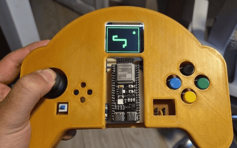
Firmware Demonstration
Each hardware subsystem was individually tested before integrating the final firmware. The following images illustrate some of the functional validation stages carried out during development, including graphical interfaces, peripheral testing and complete system operation.
TFT graphical interface used to validate menus and screen rendering.
Validation of joystick, push buttons and IMU through the embedded firmware.
Final firmware integrating all peripherals into a single educational platform.
Validation Summary
| Subsystem | Status | Validation |
|---|---|---|
| TFT Display | ✅ Operational | Graphics and menus displayed correctly. |
| Joystick | ✅ Operational | Analog navigation verified. |
| Buttons | ✅ Operational | All digital inputs responded correctly. |
| ADXL345 IMU | ✅ Operational | I²C communication successfully established. |
| LED Outputs | ✅ Operational | Independent control confirmed. |
| GPIO Expansion | ✅ Operational | Ready for external experiments. |
| Battery Power | ⚠ Pending Revision | Battery operation requires redesign due to a short circuit detected in the power management stage. The controller currently operates through the USB connection while this subsystem is improved. |
Outcome of Phase 4
This phase marked the successful completion of the GameLab Controller as a functional embedded systems educational platform. Every major subsystem was validated independently and later integrated into a single firmware, demonstrating the complete workflow developed throughout Fab Academy. The only pending improvement is the battery power subsystem, which will be redesigned in a future hardware revision to enable completely standalone operation.
Engineering Challenges & Lessons Learned
Developing the GameLab Controller involved multiple iterations where mechanical, electronic and manufacturing issues appeared unexpectedly. Rather than treating these situations as failures, they became valuable engineering lessons that improved both the final prototype and the overall development process.
Each challenge required analyzing the cause of the problem, modifying the design and validating a new solution before continuing with the next stage of development.
Challenge 1 · Failed 3D Print
During the first enclosure fabrication, the printer nozzle became clogged, interrupting material extrusion before the print could be completed. As a result, the enclosure was unusable and the printing process had to be stopped.
Root Cause
Partial blockage of the extrusion nozzle caused insufficient filament flow during printing.
Solution
The nozzle was cleaned, the printer recalibrated and the enclosure was printed again, producing a complete and dimensionally accurate part.
Challenge 2 · Mechanical Redesign
After assembling the first prototype, several openings on the front cover were found to be too narrow. The display, buttons and joystick could not be installed correctly because the tolerances were smaller than expected.
Root Cause
The CAD model did not include enough manufacturing tolerance for the printed parts.
Solution
The enclosure was redesigned in SolidWorks, increasing the clearances around the components before manufacturing the final version.
Challenge 3 · PCB Manufacturing Error
The first PCB fabrication attempt produced an incorrect board because the circuit had been designed on the Bottom Layer but the Gerber file was milled without applying the required mirror transformation.
Root Cause
Incorrect CAM preparation before sending the manufacturing files to the PCB milling machine.
Solution
The Gerber files were regenerated using the correct mirrored geometry and the PCB was manufactured again, producing a fully functional board.
Challenge 4 · Battery Power Circuit
During the final integration stage, the battery power subsystem produced a short circuit when connected to the ESP32-S3. Although the remaining electronics worked correctly through the USB connection, the portable power supply could not be safely enabled.
Root Cause
The power management circuit requires a redesign to improve electrical isolation and ensure stable operation.
Future Improvement
A second hardware revision will redesign the battery management stage, allowing the controller to operate completely independently from the USB connection.
Lessons Learned
One of the most valuable outcomes of this project was understanding that engineering is an iterative process. Every unsuccessful print, PCB revision and assembly adjustment contributed to improving the final prototype and provided practical experience that cannot be obtained through simulation alone.
These challenges reinforced the importance of validating every subsystem independently before integration, considering manufacturing tolerances during CAD design and verifying fabrication files before production. Each obstacle ultimately became an opportunity to develop a more robust and reliable educational platform.
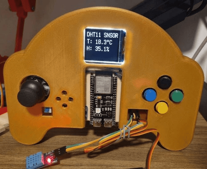
Educational Demonstrations
The GameLab Controller was conceived as a portable embedded systems laboratory where students progressively develop practical skills through interactive demonstrations. Each activity combines hardware and software concepts, allowing beginners to explore digital electronics, sensors, graphical user interfaces and embedded programming within a single integrated platform.
Example demonstrations available on the GameLab Controller for embedded systems education.
Suggested Laboratory Activities
| Demonstration | Difficulty | Main Concepts |
|---|---|---|
| LED & Button Control | ⭐ | GPIO, Digital Inputs, Digital Outputs |
| Accelerometer Monitor | ⭐⭐ | I²C Communication, Sensors, Data Acquisition |
| External Analog Sensors | ⭐⭐ | ADC, Analog Inputs, Signal Processing |
| Motion-Controlled Graphics | ⭐⭐⭐ | Graphics, Coordinate Systems, IMU Integration |
| Snake Video Game | ⭐⭐⭐ | Game Logic, Graphics, Joystick Navigation |
| GPIO Expansion Exercises | ⭐⭐⭐⭐ | External Sensors, Actuators, Embedded Interfaces |
| Robotics Integration | ⭐⭐⭐⭐ | Control Systems, Servo Motors, Mobile Robotics |
| IoT & Smart Devices | ⭐⭐⭐⭐⭐ | Wi-Fi, MQTT, Cloud Communication, ESP32 |
| Custom Laboratory Projects | ⭐⭐⭐⭐⭐ | Project-Based Learning, System Integration |
Difficulty: ⭐ Beginner ⭐⭐ Basic ⭐⭐⭐ Intermediate ⭐⭐⭐⭐ Advanced ⭐⭐⭐⭐⭐ Project Integration
Feedback from Neil
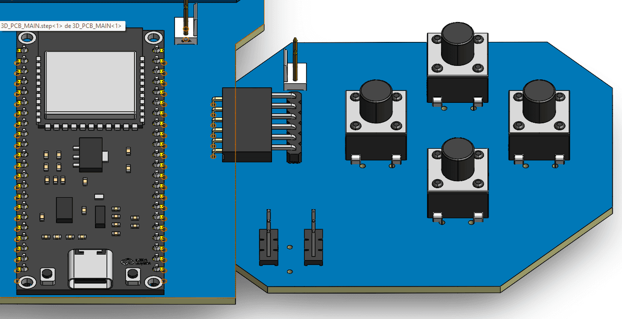
During the Final Project Review, one of the recommendations was to better explain how both custom PCBs were mechanically and electrically connected inside the enclosure. Although the controller was fully assembled, the documentation did not clearly describe the interconnection strategy between the Main PCB and the Button PCB.
Original CAD design showing the planned mechanical interconnection between both PCBs.
Original Design
The controller was originally designed to use a pair of 90-degree female headers mounted on the Main PCB and matching male headers on the Button PCB. This solution would provide both mechanical support and electrical connectivity, allowing the secondary board to plug directly into the main board without additional wiring.
Prototype Modification
During assembly, the required right-angle female headers were not available locally. To avoid delaying the project, the final prototype was adapted using only right-angle male headers. Both PCBs were then permanently interconnected through carefully soldered joints, maintaining the same electrical functionality while sacrificing the detachable mechanical connection originally planned.
Lesson Learned
This experience highlighted the importance of considering component availability during the design stage. Future hardware revisions will implement the original connector configuration to improve assembly, maintenance and long-term serviceability.
Final Conclusion
The GameLab Controller successfully evolved from an initial hand-drawn concept into a fully functional embedded systems educational platform. Throughout the Fab Academy, the project progressively integrated computer- aided design, electronics development, digital fabrication, embedded programming and mechanical assembly into a single portable device designed specifically for learning.
Beyond the technical implementation, this project demonstrates how multiple digital fabrication processes can converge into a coherent educational product. Custom PCBs, 3D printed mechanical parts, embedded firmware and graphical interfaces were not developed as isolated assignments, but as interconnected subsystems working together to solve a real educational challenge.
Although the first prototype successfully validates the overall concept, several opportunities remain for future improvement. A second hardware revision will integrate the electronics into a single PCB, redesign the battery management circuit and continue refining the mechanical enclosure to simplify manufacturing and assembly. These improvements will further increase the robustness and portability of the platform.
The greatest value of the GameLab Controller lies in its educational potential. By combining sensors, displays, user inputs, embedded programming and expansion capabilities within one compact device, students can experiment with a wide range of embedded systems concepts without requiring multiple disconnected development boards. This transforms the controller into a reusable laboratory that can support programming exercises, guided laboratory activities and introductory robotics courses.
What Fab Academy Made Possible
Fab Academy provided much more than a collection of technical skills—it established a complete engineering workflow. From defining the initial idea and planning the project, to designing electronics, manufacturing custom hardware, programming embedded systems and documenting every iteration, each weekly assignment became an essential building block of the final result. The GameLab Controller represents not only a finished prototype, but also the integration of the knowledge, methodologies and mindset developed throughout the program.
Downloads
All downloadable resources required to reproduce the GameLab Controller are stored directly within this GitLab repository. The files include the mechanical design, PCB manufacturing files, source code, printing assets, and documentation developed throughout the project.
| Resource | Description | Format | Download |
|---|---|---|---|
| 🖨️ 3D Controller Design | Complete 3D CAD model of the controller enclosure and mechanical components. | ZIP | Download |
| 🎨 Printing Graphics | Artwork and printable graphics used for the controller labels and assembly. | ZIP | Download |
| 📄 Electrical Schematic | Complete schematic diagram of the custom PCB. | View | |
| ⚡ EasyEDA Project | Editable EasyEDA project containing the schematic and PCB layout. | ZIP | Download |
| 🏭 Gerber Files | Manufacturing files for professional PCB fabrication. | ZIP | Download |
| 💻 Arduino Programs | Source code developed for the ESP32-based controller. | ZIP | Download |
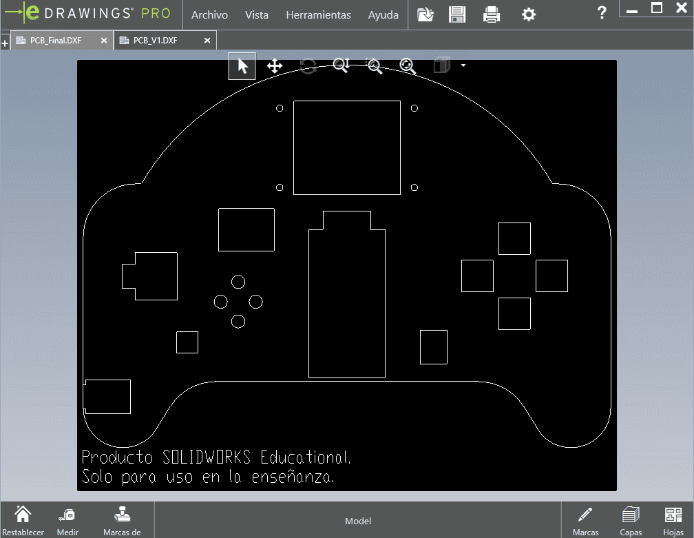
| ✂️ PCB Vector Files | Vector files used for PCB fabrication and laser/CNC workflows. | ZIP | Download |
All downloadable resources are included directly in the GitLab repository, ensuring long-term accessibility and compliance with Fab Academy documentation guidelines.